Alpha Charlie
-
Buttons, Switches and Lights
07/24/2015 at 01:41 • 0 commentsIn addition to the touchscreen, the Patch-A-Tron has 2 LEDs, 9 momentary pushbuttons and a 16 key keypad for I/O. The 16 key keypad allows the user to save and recall configurations. The LEDs provide feedback on the keypad input. 8 of the 9 SPST buttons are used to select/mute/unmute the 8 channels of the Patch-A-Tron. The remaining button is a master reset that disables all bends and returns the configuration to 'stock'. It is the red button on the upper left corner of the TR-626.
Connections are:
- 16 key keypad - Rows pins 3, 4, 5, 6; columns pins 7, 8, 9, 10
- 8 'Mute/Select' buttons - Pins 38 ,39, 40, 41, 42, 43 ,44, 45
- RESET button - Pin 37
- Programming LEDs - Pins 22, 23
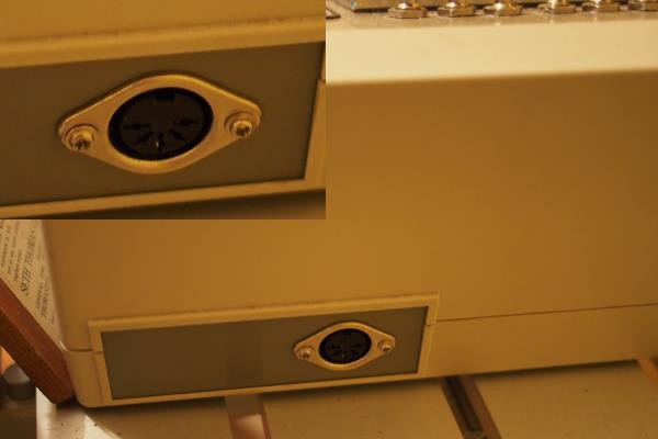
The Roland TR-626 has 8 SPST switches and 8 SPDT On-Off-(ON momentary) switches on the right upper corner which are connected to dedicated circuit bends. (the Momentary switches are the top row and are connected to the RAM of the TR-626**.) The four knobs and switches in the middle 'pitch bend' four of the Roland's output channels. With each switch turning it's respective pitch bend on or off.
**The RAM bends sound really cool but must be turned off when not in use as they can make the unit unstable.
-
Patch-A-Tron RA8875 Video Controller
07/24/2015 at 01:16 • 0 commentsThe Patch-A-Tron uses the RA8875 video controller board from Adafruit. This controller works via SPI and handles all of the low-level rendering as well as the touchscreen control. This makes it really nice for Arduino. Connection is via the 6 pin SPI connector in the middle of the Mega. (+Vin, GND, MISO, MOSI SCK, RST) with pin 11 on the Arduino being used for the INT and pin 12 for the CS on the RA8875.
In the photo above the blue and green wires go to pin 11, and 12 on the Arduino the rest connect to the 6 pin SPI connector in the center of the Mega. Both the video out and touchscreen in are SPI, so wiring it is extremely simple. (Note also that there is a layer of Kaptan tape and another layer of 2 sided tape insulating and affixing the RA8875 to the aluminum plate. Which is not really visible in the photo. Without it the RA8875 would short out on the faceplate.)![]()
The Patch-A-Tron Arduino Sketch uses the RA8875 library available here -
-
Patch-a-Tron MIDI Implementation
06/30/2015 at 23:36 • 0 commentsIncluded in the Patch-a-Tron hardware is a MIDI implementation that allows the circuit bends in the Patch-A-Tron to be controlled remotely. The hardware interface consists of the standard MIDI DIN connector fed to the Arduino UART through by an opto-isolator, per the MIDI specification. (details at - http://www.midi.org/techspecs/electrispec.php)
![]()
The schematic below shows how to connect MIDI hardware to the Arduino. The arduino should be connected via one of its hardware serial ports. [Patch-a-Tron uses port 2 by default on the Mega, pins 16(TX) and 17(RX)]
![]()
The software currently only implements the Control Change and Program Change MIDI events with the idea being that the same sequencer could control both the Roland and the Patch-a-Tron and get repeatable - predictable - sequencable circuit bends that go with the sequenced rythm. Control Change allows the user to choose memory banks (A-D). Program Change selects pitch bends to activate. Banks A-C only save 128 bends per bank(0-127). Each 'bend' consists of one 'bus' of of max 48 switches. Bank D saves only 16 slots(0-15). But each slot contains the configuration for all 384 switches.
-
Pitch Clock Mod
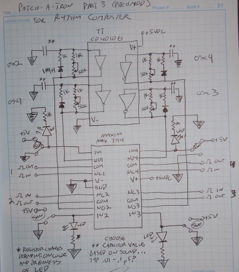
06/26/2015 at 03:19 • 0 commentsHere is the basic circuit I used to create my own pitch clocks for 4 of the output channels. The TI CD40106 runs the 4 oscillators. Each has it's own potentiometer. The capacitor for each oscillator should be adjusted to taste for the channel you are modding so that the pitch variation is noticeable and pleasing to the ear when the potentiometer is turned...
(Note - In the drawing below, the switch numbers are transposed on the right hand lower side... 3 should be above 4. Ooops!)
![]()
The four oscillator signals run to the NO connections of the 4 switches in the Max394. The NC connections of each switch are connected to the actual Roland TR-626 pitch clocks signals on the gate array(IC 13). The COM are connected to the clock inputs on IC14 of the TR-626. This allows me to choose between the Roland clocks and my pitch modded clocks with the four spdt switches.
* The value of the resistor connected to each LED will depend upon the diode forward voltage and current for the LED. 150-330 ohms is typical. (there's a calculator you can use here if you know the specs for your LEDs.)
** The value of the capacitors for each oscillator will be dependent upon the clock signals you are replacing and how far you wish to bend them... the frequency out will be around 1/1.2*RC (just count the 500K pot and the 1k. Ignore the diode/1k leg in the freq calculation. It's just there to keep the pulse width low on the generated signal. The Roland clock is not on a 50% duty cycle. It generates fixed width pulses...) For the caps themselves I use polyester or mylar. I started with 0.1uF and adjusted from there by ear. USe a larger capacitor for a lower pitch, a smaller capacitor for a higher pitch. To limit the highest pitch reachable on the high end, you can increase the 1k resistor connected to the pot to 3.3k or 4.7k. The pots are 500k, If you can find them use reverse logarithmic pots. Linear will work in a pinch but adjusts the frequency linearly, which is not how humans perceive pitch.
If you decide to try this mod- Be Careful! Installing this circuit in the Roland is a nightmare. It was 100% the most difficult part of the entire project. Both IC13 and IC14 are SMT chips and doing this mod means either desoldering one of them or cutting traces on the board. Neither option is easy. Below is a video showing the mod. You can see what I mean.
Also- unlike the Patch-a-tron which requires minimum tools to construct, an oscilloscope is almost required to troubleshoot this mod if anything goes wrong.
-
Switch Array Stack
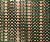
06/23/2015 at 08:25 • 0 commentsThe heart of the Patch-a-Tron is the stack of 3 CD22M3494 crosspoint array ICs. Together they control the 384 analog switches that turn our bends on and off. The IC uses 7 pins for addressing, 1 for switch data and 1 as a strobe (or clock) to time things. All of these pins and also the 8 x-axis pins and the positive and negative power pins are all connected in parallel for all of the ICs. Since the ICs share over half of their pins, it made sense to me to stack them vertically and run all of their common pins through a 'bus' of parallel wires.I used Busboard 'zig-zag' trace prototyping board (part no. BB02) for the stack and cut it to size because the zig-zag trace pattern offered the easiest routing.
![]()
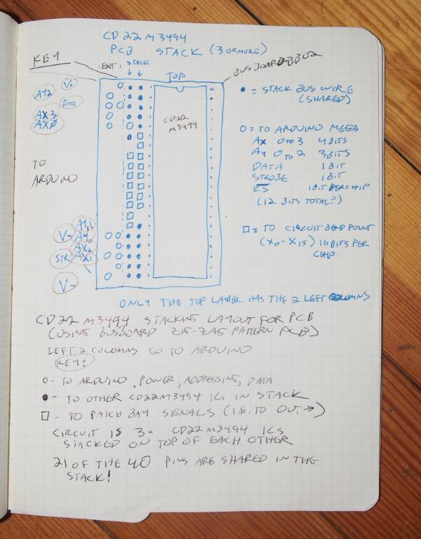
Below is the board layout and wiring diagram for the switch stack. The entire circuit consists of 3 boards layed out as below each with it's own CD22M3494, all stacked together vertically. (Sorry there's no schematic yet. I literally designed the circuit in 3 dimensions in my head, then just constructed it. It has never been drawn out fully in 2 dimensions...)
![]()
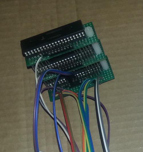
And below you can see the finished stack of 384 analog switches! (the wires all go to the Arduino, the 16 switch connections for each IC are the male dupont headers on each layer).
![]()
Below is a schematic of the interface between the Arduino and the 3x CD22M3494 ICs. One thing that is worth ntoing about the CD22M3494 is that is has a separate logic ground than signal ground. The Vss pin is for the logic that controls the switches. The analog ground for the signals is the Vee pin. This is a nice feature escpecially if you're mixing different systems together. But since I already tied the Arduino into the Roland power supply, I ended up putting an SPST switch between Vss amd Vee so that I can selectively tie them together or not (whichever has the least noise).
![]()
-
Patch-a-Tron Walkthrough
06/21/2015 at 10:22 • 0 commentsThis video shows a walkthrough of how the patch-a-tron UI works.
-
TR-626 patch-a-tron demo
06/21/2015 at 10:18 • 0 commentsThis video shows the Patch-a-tron after it's marraige to the Roland TR-626 but prior to the pitch clock mod.
-
BreadBoard Demo
06/21/2015 at 10:01 • 0 commentsThis video shows the patch-a-tron right after I made it, hooked up to a Roland TR-505 (I didn't know whether it would work and didn't want to waste my precious TR-626.)
The Rythm Composter
Circuit Bending an old Roland Drum Machine using an Arduino Mega some cross-point arrays some schmitt triggers and a touch-screen