Close
0%
0%

ESP8266 Parasite

A development board built to be able to go inside another project to enable wifi control

Similar projects worth following
Using an ESP8266-201, and slave PIC12fs this board will allow remote control using either 3 PWM controlled mosfets, or another 8 standard GPIO pins. Multiple Embedded switch mode supplies ensure both efficiency and high voltage input range

The board is a WiFi enabled interface board, that I am designing to be small but able to control a wide variety of devices, an ESP8266 does the heavy lifting, providing WiFi interaction, a web server (for configuration and control) and some GPIO, this is also connected to a second microcontroller, the PIC12LF1552 from microchip, small footprint, and a 32mhz crystal less clock means this can be doing something entirely independant of the main CPU, whether its running PWM, or bit-banging midi.

  • 1 × PIC12LF1552 Used as a slave CPU to offload IO processing
  • 1 × ESP8266-201 Main CPU and wifi access for the project
  • 1 × FT230x Serial adaptor, for pushing new firmware to the ESP-201, only on development board

  • SDK Woes

    unfoundbug07/17/2015 at 09:56 0 comments

    Well, I seem to be having an issue at the moment, now that the control software is close to completion I can actually send data to the ESP at a higher data rate (about 90KB/s) and there seems to be an issue, this will run fine for a variable length of time and at that point, the ESP seems to experience a partial crash. The socket is left open on the ESP side, and the control program then sees communication timeouts. No further interaction can be seen from that port on the ESP. The strange bit happens after, the timer I have running to kick out broadcast packets the controller listens for still work. Even though the socket for main transfer is dead and appears to have had an exception, the rest of the program carries on

  • IDE configuration

    unfoundbug07/06/2015 at 17:16 0 comments

    Spent today updating the build scripts and setting up a new IDE project. With Visual Studio setup, including the SDK headers and binding the build/clean/rebuild scripts means I get an IDE I am far more comfortable with, with the added bonus of Intellisense , this is one feature you very quickly miss when you don't have it.

  • First Successful Flash

    unfoundbug07/03/2015 at 12:33 2 comments

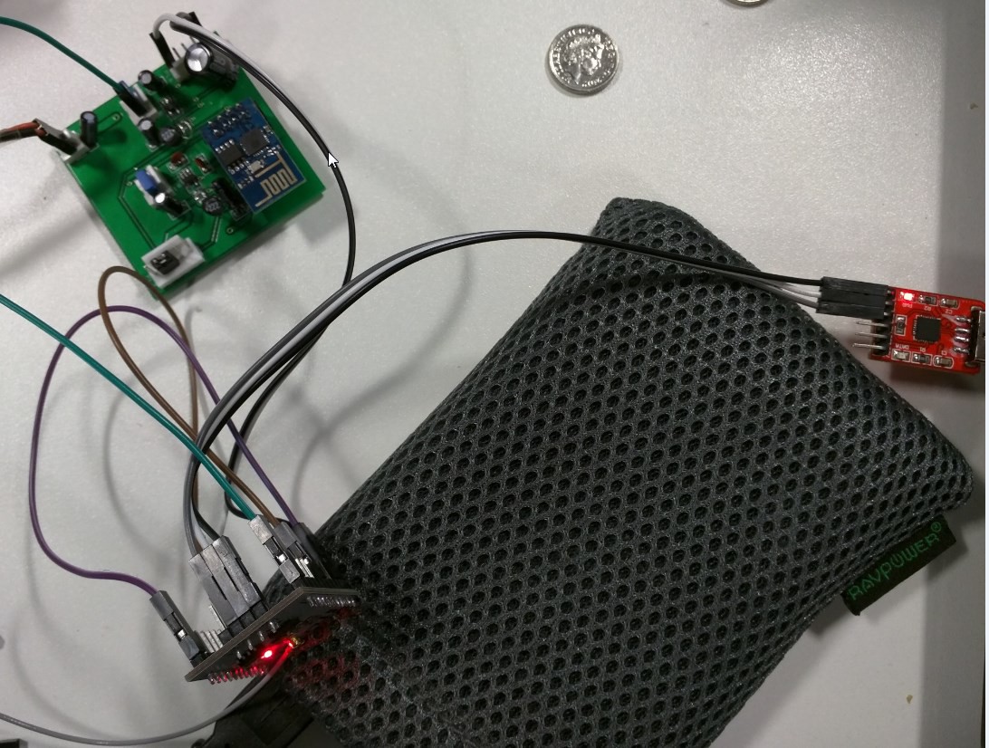
    Actually got the 201 to flash, its certainly worth remembering that on these larger boards, GPIO15 needs to be pulled to ground in order to flash, as well as GPIO0, will need a quick tweak of the design to compensate for that

    Currently the 201 is leeching off a project using the ESP-01 for power so I dont have to send off for the boards until I'm sure there isnt going to be another subtle difference like there was with flashing.

  • Initial Layout

    unfoundbug06/30/2015 at 12:21 0 comments

    Just finished up the first actual layout for the new board, a bit annoying to route around the FTDI chip, but everything connected up, allowing both the on board adapter, or an external serial controller to communicate with the device for programming.

    Learning from previous mistakes, every pin is labelled on the silkscreen so once it comes back from manufacture, its alot easier to deal with

  • Circuit Board Update

    unfoundbug06/26/2015 at 12:23 0 comments

    Well, finally got the schematic to where I am happy, and the PCB just had its first layout

View all 5 project logs

Enjoy this project?

Share

Discussions

MORE PCB wrote 01/05/2019 at 04:12 point

nice

  Are you sure? yes | no

Similar Projects

Does this project spark your interest?

Become a member to follow this project and never miss any updates