Close
0%
0%

Power Glove Universal HID

An overhaul of the iconic Power Glove to allow it to control robots, drones or anything your heart desires. It's so... good.

Similar projects worth following
In a world... where wires are a thing of the past, pound signs are now hashtags and there is always a “new black,” one man will revive a gaming icon in order to preserve the past… and control the future.

The ultimate goal of the Power Glove UHID (Universal Human Interface Device) project is to revamp the 1989 Nintendo Power Glove with modern sensors and wireless communication, giving you the ability to use gesture and motion controls with almost anything you can think of, in style.

Overview

A ways back, I acquired a Power Glove after winning an auction for a lot of NES controllers and accessories. The Glove sat in storage for some time while classes kept me occupied. Eventually I discovered the 20th Anniversary Edition Power Glove created by Matt Mechtley and Dillon Markey's Power Glove modification that boosted his stop motion productivity. With these two projects in mind, I dug out my Glove and got to work thinking of ways to help bring the glove out of obscurity. Following in the footsteps of the 20th Anniversary Glove, I decided to imbue the Glove with a modern IMU and Wi-Fi, bringing it into the world of IoT.

Here's What's Gonna Happen

The keypad, status LED and awesome retro form will be preserved, but under the hood, brand new custom boards, one featuring a microcontroller, LiPo charger and WiFi, the other an IMU and new flex sensors, will be designed and installed.

Down the line, I hope to have the Glove feature a interchangeable wireless interface system. The Wi-Fi module will be able to be replaced with a Bluetooth module, RC transmitter, IR transmitter or other custom RF or USB HID dongle.

Here's What's Happened So Far

The first versions of the board have been manufactured and used to produce the AR Drone demo seen at Maker Faire 2016. An article written by Mike Szczys further details the usage of the Power Glove UHID as a gesture controller in said demo. A new Power Glove was picked up on eBay to house the components (don't worry, all original electronics were preserved!). Full details of the journey thus far can be found in the project logs.

  • 1 × Nintendo Power Glove No exceptions!
  • 1 × Teensy LC/3 Potentially will work well with an ATmega based Arduino
  • 1 × ESP8266 Module ESP-01, ESP-07, ESP-12E work well
  • 4 × Flex Sensors Original working sensors preferred, Spectra Symnol 2.2" otherwise
  • 1 × Pololu AltIMU-10 v4 or v3, both work well

View all 7 components

  • Boards on Tindie, (Rudimentary) Build Instructions added!

    Nolan Moore08/23/2018 at 17:01 0 comments

    Hello, you beautiful people, you. It's obviously been a long time since I've shared any news on this project, and even more obvious is the fact that I've sinned letting such a great project sit for so long without any love or updates.

    I'm posting today, to tell you that the boards will (very) soon be up for sale on Tindie! I must apologize, my own quest for perfection on this project prevented me from putting them in the shop until a fully detailed build log was published, but while trying to finish that, I ended up on other work projects, switching jobs and most recently becoming a homeowner (WOO HOO!).

    But after settling into this new job, I've become enchanted with the freedom I had to build cool projects, and I want to get back into the scene. I've had discussions with people lately about the cool projects they want to build and control using a power Glove, and I've had a few requests asking when the boards would finally be for sale.

    With all this in mind, I've decided that I would finally put together at least a quick and dirty step-by-step guide so that I can allow myself to let loose the boards upon the world. Also I've decided that I will get my Power Glove up and running again and fly a drone by the 23rd of September (one month from now). A longer goal is to create a version 2.0 of the board, and though I won't be setting a timeframe for it, I'd like to implement BLE and Wi-Fi, allowing for more communication options.

    I've submitted the product page for approval and will post it as soon as it is available.

    Thank you all for your support and interest in the 2 years since the project was created. I can't wait to see what you build with your Gloves!

    Nolan

  • Boards Are In! Let's Put It All Together!

    Nolan Moore05/01/2016 at 19:48 0 comments

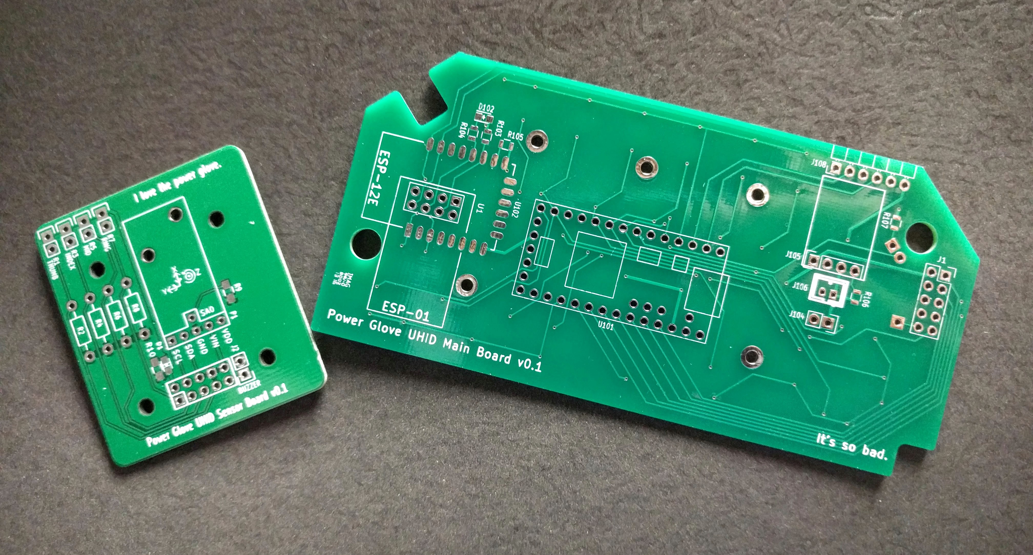
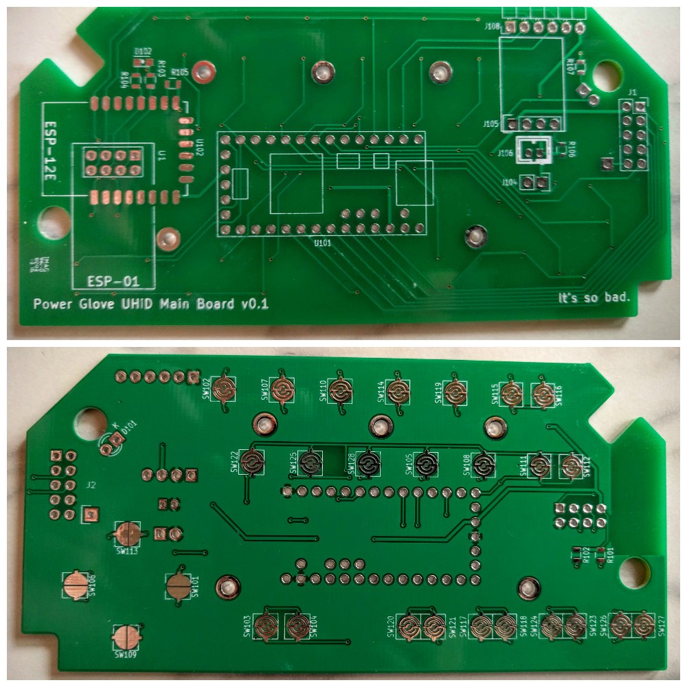
    This is the big one! After a few weeks, both boards are finally here! Small disclaimer though: the control board actually arrived a couple weeks prior to the sensor board, but since I found myself still trying to catch up on logs, I ended up waiting to write this one until both boards had arrived and been tested. As you can see in the photo below, they came from two different board houses. The sensor board on the left was produced by Seeed Studio, and the control board on the right (dubbed the Main Board on the silkscreen) was made by Accutrace (a.k.a. PCB4U.com).

    Both boards are of good quality, but due to a much sharper silkscreen and a deeper color (and better quality) soldermask, the control board totally took the cake. I'd ordered boards from both houses previously for work projects, so I knew what sort of quality I would getting on these ones. Perhaps I'll do a separate post elsewhere one of these days on differences between various board houses...

    But anyway, let's get these boards installed!

    The Control Board

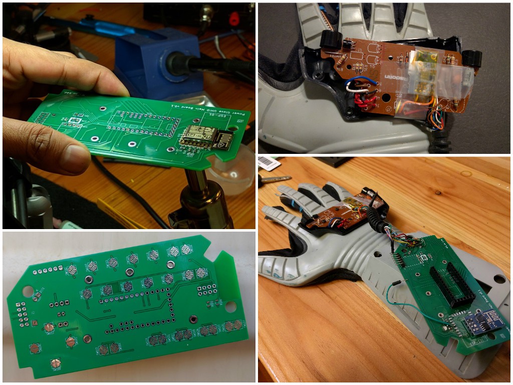
    To install this board, I'll be replacing the modified board in the old glove (not the new one covered in the previous log), but first I've gotta get the board assembled. There are relatively few components, making this a fairly quick procedure. This is fortunate as there were barely any photos taken during the assembly and testing of the new board (I mean, there's not too much going on just yet). I do have this mini collage though:

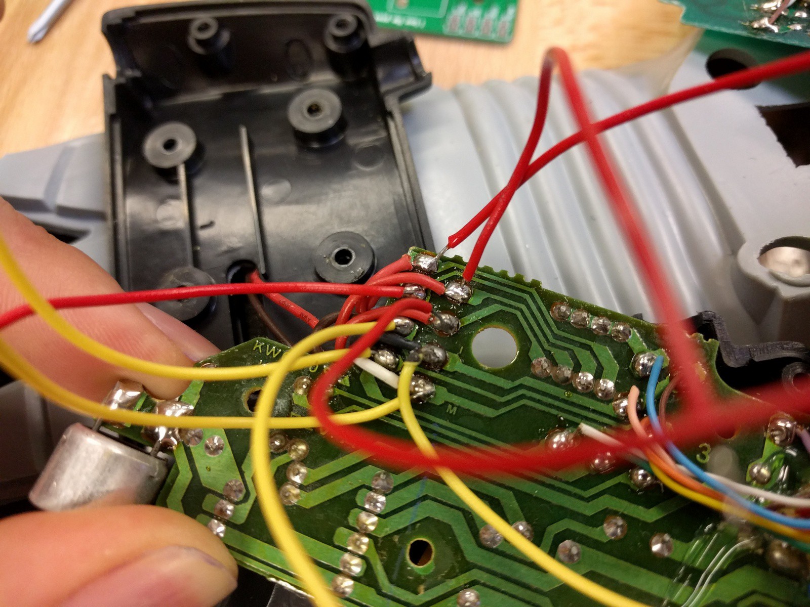
    Not shown in the photos above, the back half of the enclosure was modified to fit the various components that proved to be a bit too tall to fit within the case. Using a Dremel, a hole for the Pololu voltage regulator and serial header was made along the top (narrower long side) of the case. The ESP-01 was also a bit too high, but in the interests of not cutting too many holes, was left alone (the final testing unit may have had more tape holding it together than was envisioned). To put it bluntly, besides the planned ESP-12E and the top-side LED, nothing would've properly fit into the case without modification. Achieving a slimmer profile will require future boards to use more SMD components and preferably no through-hole modules.

    A few other expected issues arose during testing. I'll list them out here with the lessons learned in bold.

    • Don't forget your required components. As mentioned in a previous log, I had forgotten to add reset and bootloader buttons to the ESP sub circuit. After soldering a jumper wire to the ESP's GPIO0 pin directly to be able to set bootloader mode during a hard reset, programming the ESP became only a slight PITA.
    • Plan ahead. Though not necessarily a design issue, the voltage dividers needed for the glove's flex sensors still had no designated footprints. Those resistors would be found on the sensor board. I ended up soldering the resistors to the incoming wires from the sensor board directly. Ugly, but sufficient.
    • You get what you pay for. A final issue presented itself in the actual components. As the first picture in the collage shows, I originally used an ESP-12 WiFi module. Unfortunately, this module, as well as another I replaced it with soon after, were sourced from what I believed to be a somewhat respectable international distributor on Aliexpress. After getting them soldered to the board, I found them to be DOA as they refused to respond to firmware upload attempts. In the end, I replaced both of them with a working ESP-01 module (not exactly less sketchy, got it on eBay from China, but thank goodness I put that extra footprint in there!).

    Board issues out of the way, there were a couple necessary changes to make to the Teensy's firmware. A new configuration was set for the board's new keypad layout, and pin definitions were updated to match the new pinout.

    With the glove finally ready for use, a single cell Li-Po was connected to the control board and hidden in the gauntlet underneath the enclosure. With the USB battery pack and previous mess of wires gone,...

    Read more »

  • Unboxing a BRAND NEW Power Glove

    Nolan Moore05/01/2016 at 07:07 0 comments

    Fantastic News!

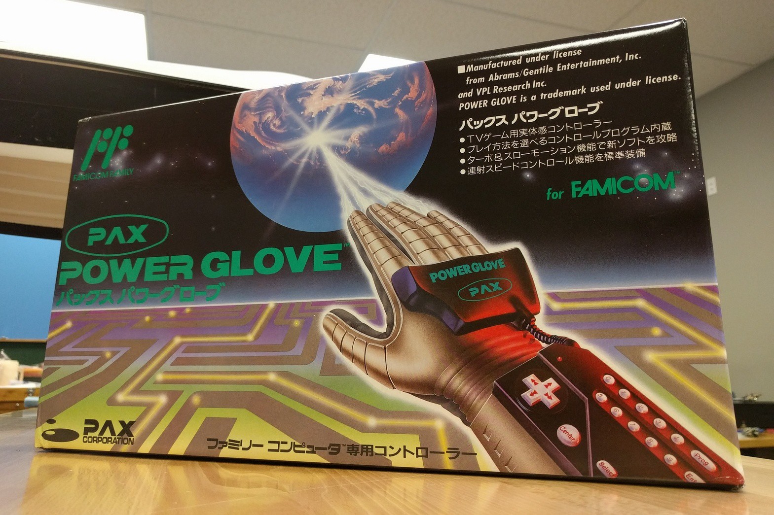
    After weeks of scouring eBay for the perfect deal, I managed to acquire a brand new Famicom Power Glove which I will be using for this project from now on! Marvel in the glory that is a recently opened 1989 video game accessory!

    Having a brand new glove nets me these important features:

    • Brand new, very clean unit: The original one I started with had been in use and storage for some 27 odd years before finally being used once again. With this new glove, I'll have a beautiful, new (it's matte so still no shiny) glove to show off. This also allows me to use the old glove as a testing platform which I won't be afraid to get dirty or further mutilate for the cause!
    • Untouched flex sensors: I hope to find the new glove's flex sensors in pristine condition, allowing me to NOT completely decimate the aesthetic value of the glove by ripping its fingers open to install new sensors.
    • A sub-par gaming experience: Should I ever acquire a Famicom and at least one Power Glove specific game, I can finally live the awesome, yet wholly disappointing experience that thousands of kids in the late 80's went through after unwrapping a Power Glove on their birthdays or Christmas. The reason I did not test the Glove on an NES sooner was because I never received the required sensor bar unit with my previous eBay find.

    The Unboxing

    There are some 20 odd photos in the unboxing, so I'll spare us both the trouble of posting all those here. Instead, here's a convenient Google Photos album:

    https://goo.gl/photos/Tco4qDA3z9MXLcUo6

    A couple neat details to note about the glove after the unboxing:

    • Besides the branding, logos, language and connector on the sensor unit, the glove appears to be essentially the same as the American Mattel version. Not too surprising, but we'll see if there are any differences under the hood.
    • As you can see in the last photo, the instruction manual/programming guide features some pretty cool cartoon illustrations of proper use of the glove. It would be nice to see more graphics like that now-a-days.
    • It's just too freakin' cool.

    Mini Teardown

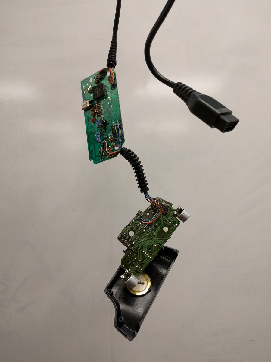
    From the teardown of the previous glove, I didn't expect to find anything really different about this glove, but regardless since it was going to be gutted soon anyway, I figured I might as well share the details with you lovely people right now. There are only a few pics, but if anyone would like any specific detailed shots, please feel free to leave a comment. As Dave Jones would say, "don't plug it in, take it apart!"


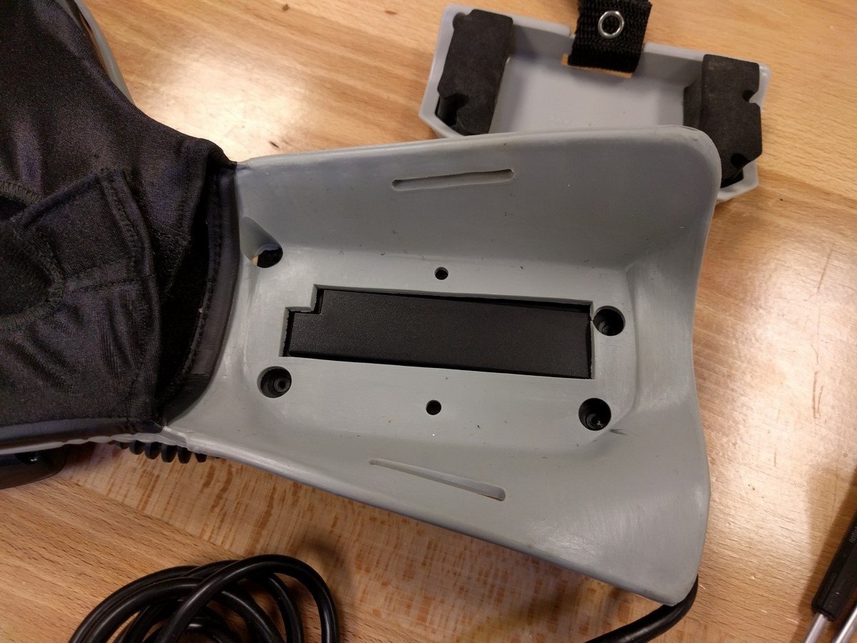
    Four screws hold the foam arm guard plate, rubber, and control board enclosure together

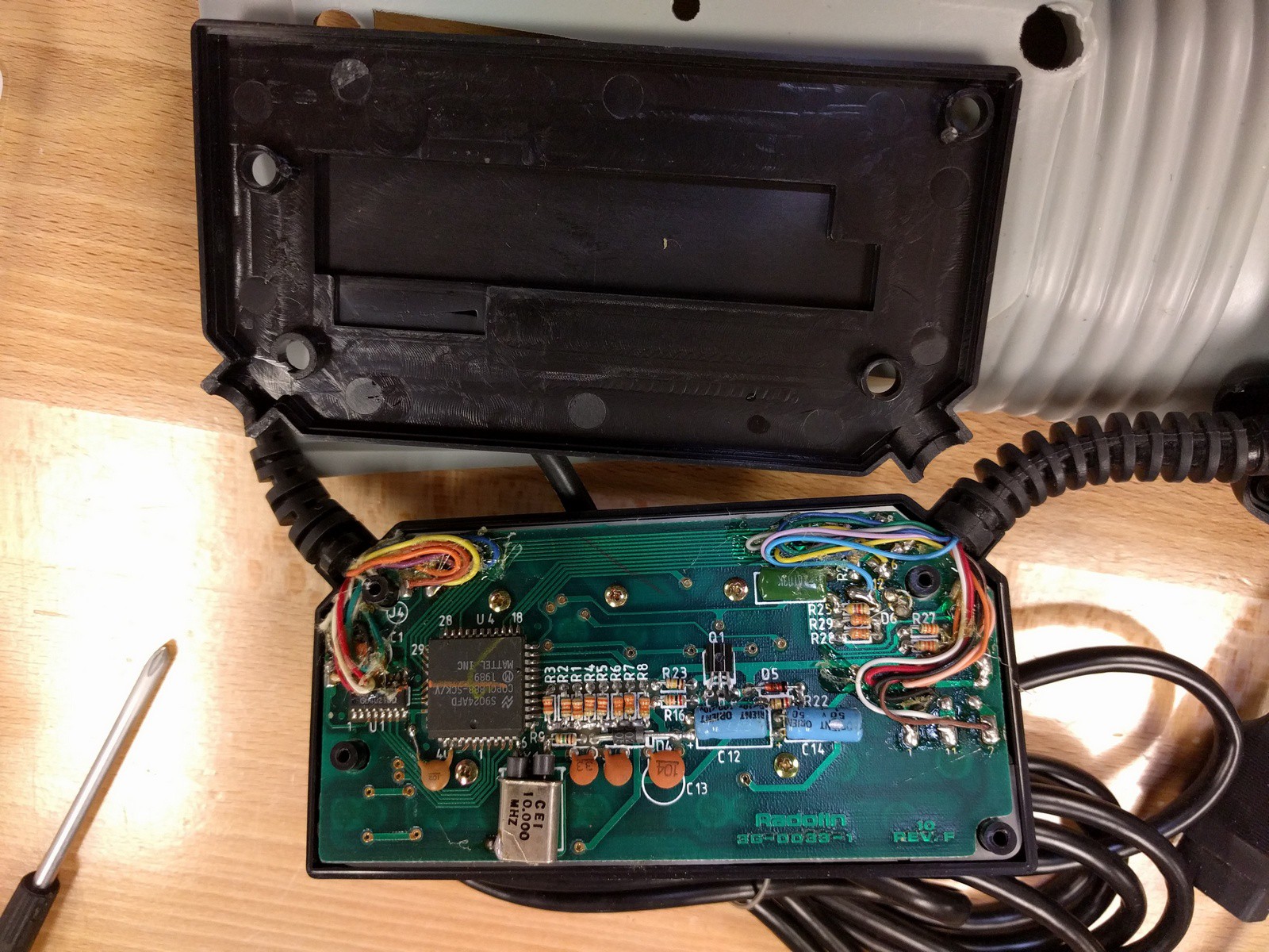
    The control board. This one is rev F, whereas the Mattel glove has a rev E board.

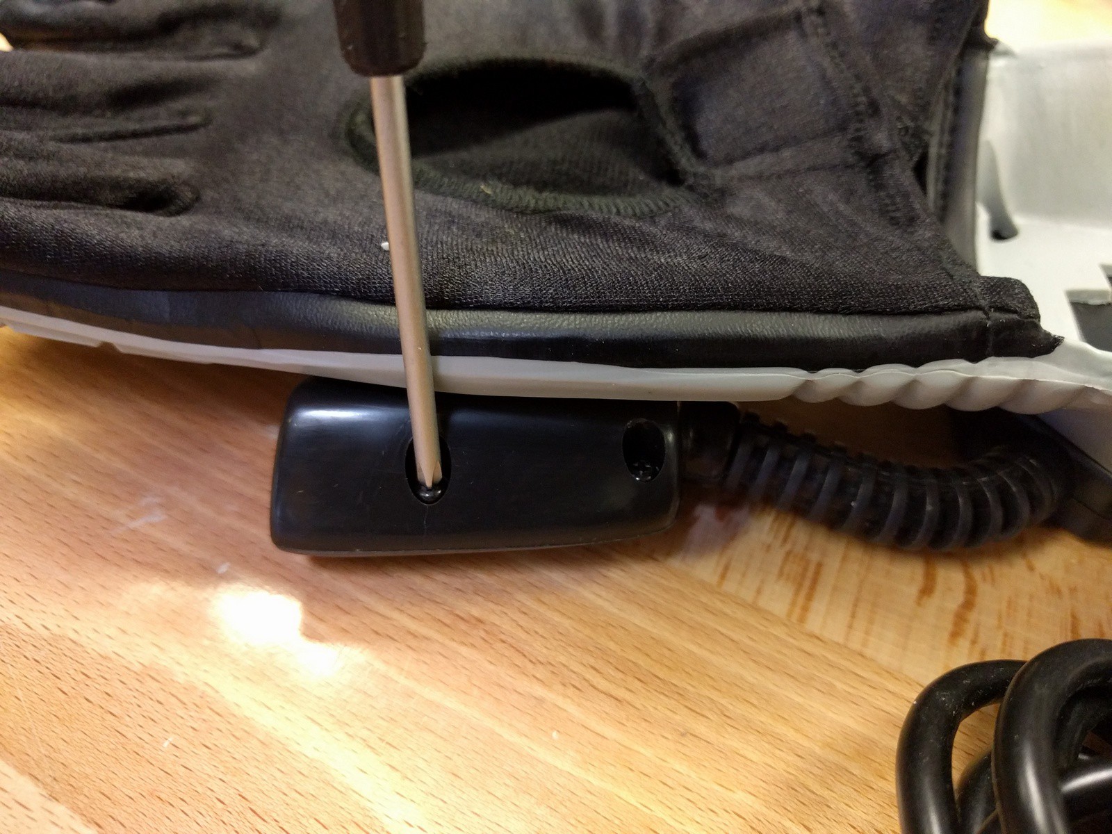
    Four screws later...

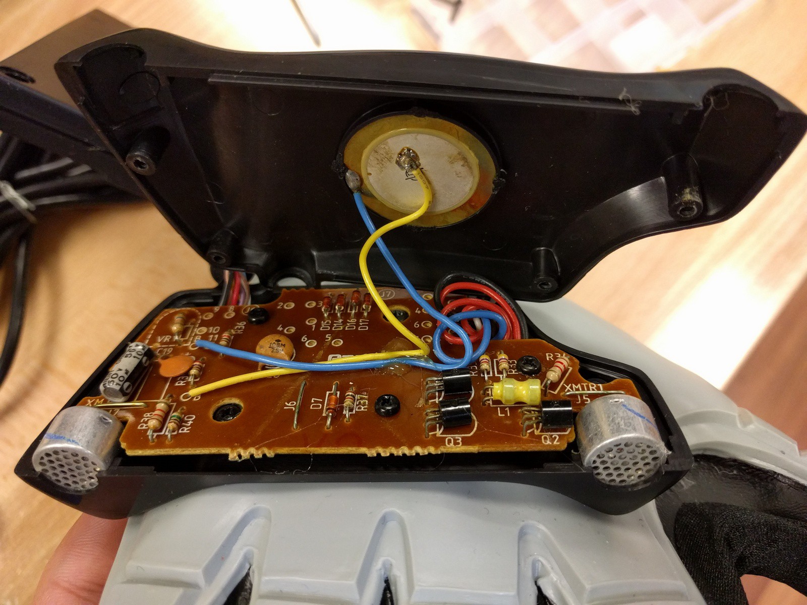
    Other than the color of the ultrasonic sensor housings, pretty much identical to the Mattel version under the hood

    Wires to the flex sensor connections for testing

    Freshly (but gently) ripped guts


    The good news is, the flex sensors seem to work well. There are still some fluctuations in the values, but compared the previous glove's sensors, these are fairly solid and will be useful. Thank goodness, I was REALLY hoping I wouldn't have to cut the fingers open again (though now I can freely mess with the other glove to perhaps find a less intrusive means of replacing the sensors).

    Other than that, not too much to note about the components. Next time, we'll hopefully get some boards installed so that some real testing can finally begin!

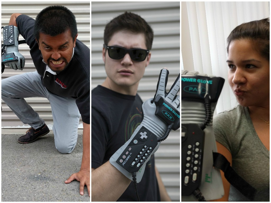
    But, before I go... obligatory awesome shots:

  • Log Catch Up, Part Two

    Nolan Moore04/26/2016 at 23:45 0 comments

    Yes, the wait is over! Part 2 has finally arrived!

    In this log, I’ll summarize the design process I went through with Eagle and later KiCad with the control and sensor board replacements for the Power Glove. To be honest, this information is a bit outdated as I have already received the boards mentioned herein, but I feel obligated to catch up and put out a full build log. If you’re not interested in the design process and want to see some results NOW, hang tight! I’ll be posting a log with the boards and current prototype soon. Otherwise, have a sit in your favorite chair (or other accommodating local seating), relax and read on!

    Getting Started in Eagle

    The initial design was very simple, yet perhaps slightly over engineered. It featured a standard ATmega328P-based Arduino as the brains for ease of design. FTDI and ICSP headers would be provided for programming and debugging. SPI GPIO expanders (MCP23S08 and MCP23S17) would be used to collect the button inputs, taking advantage of the chips' interrupt features to eliminate the need for polling. 5V from the FTDI cable would power the Arduino as well as a 3.3V LDO for the external sensors. Any sort of expansion port to provide additional features or extra prototyping capabilities was absent.

    After taking initial measurements of the Power Glove's main control board, I drew up the board outline, placed mounting holes, created the spiral button pad footprints and marked said button pad positions on the board, attempting to stay as true to the original as possible. Unfortunately these measurements were made hastily in anticipation of getting the board fabbed quickly, and their inaccuracies showed when printing out the board layout for physical design checks. Still, I went ahead and began adding my previously chosen set of components to the board. The button footprints were initially on the top layer but were flipped to the bottom to follow the standard of placing components on the top layer. The ATmega, GPIO expanders and voltage regulator were added as SMD components, while through hole headers were used for a reset button and ICSP, FTDI and sensor board connectors. I started routing traced and made decent progress, but ultimately the board was left unfinished. The project was temporarily dropped when a project at work pulled me away and kept me constantly busy.

    The unfinished Control Board, version 1
    A Minor Detour

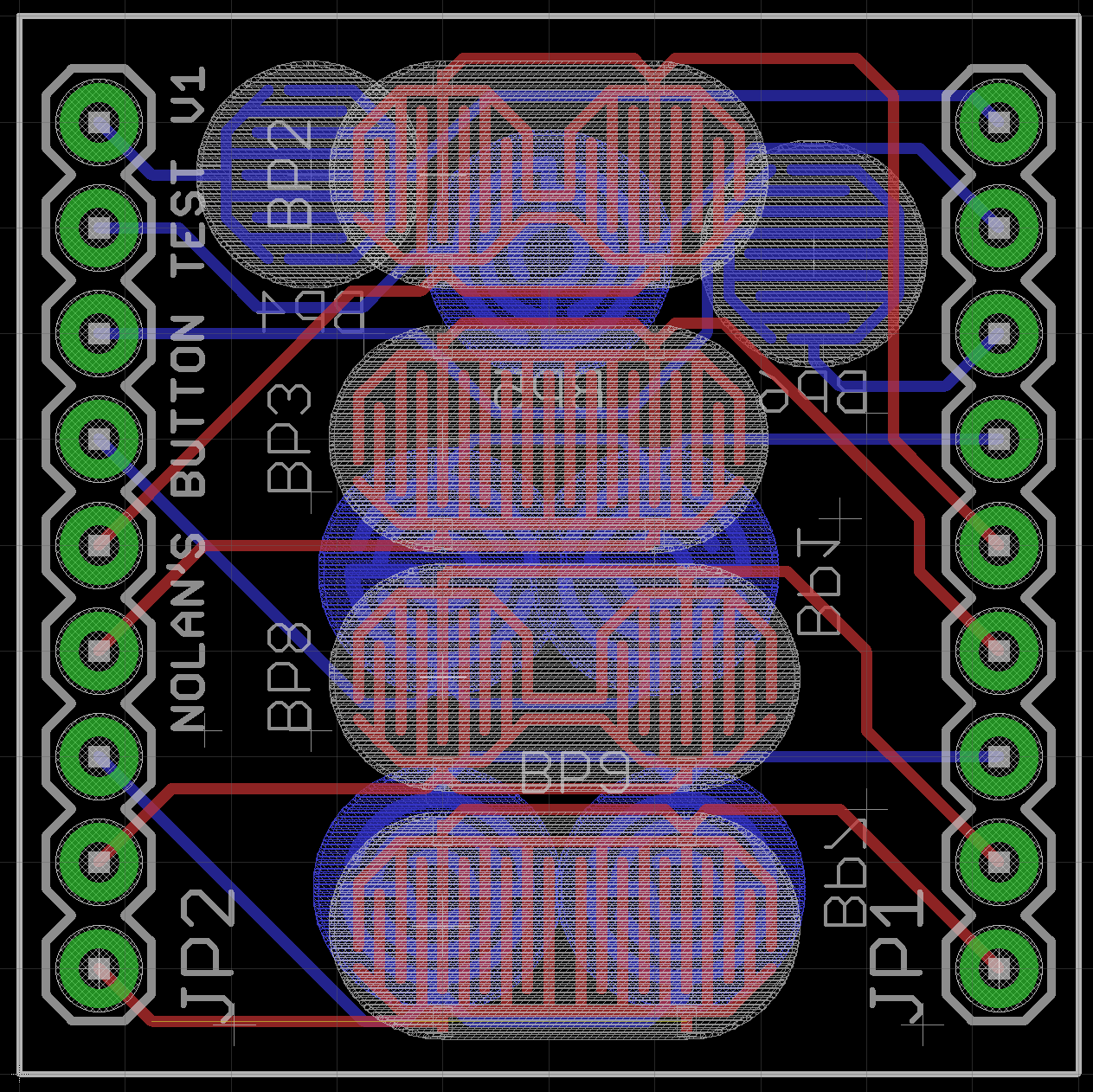
    During the time away from the project, I had been looking into button pads on other controllers and remote controls and wanted to try some different styles. New octagonal button footprints were created, and a test board with various types of pads was hastily cobbled together with the idea of comparing the designs.

    The board was manufactured by OSH Park but was ultimately unused due to a lack of time and perceived usefulness. Still, finally seeing the little gold button pads on a board of my own making was pretty neat.

    The Button Tester Widget

    Fly Like an Eagle: Round 2

    When the project was picked up again sometime later, attempts to make new, more accurate measurements were made, resulting in a new board outline and adjustments of the button pads and mounting holes. The new measurements proved to be only slightly more accurate, but I was able to tune out my OCD and decided to continue with a vow to come back later and improve them. This version ended up retaining the button pads on the top layer

    In the interests of getting a board on which I could actually begin protoptyping, a need for more through hole components was recognized. The ATmega-based Arduino was replaced with a Teensy 3 in anticipation of needing more computing power, and DIP versions of the GPIO expanders were used. An LED finally found it's way onto the board, occupying the same position as the original. Unfortunately I found difficulty trying to find convenient places for the components as the numerous button pads took up a large amount of space, and the thin enclosure of the board left little room for anything...

    Read more »

  • Prototype Project: Flying a Quadcopter

    Nolan Moore03/27/2016 at 01:33 0 comments

    Before I finally get to the log detailing the new board design, allow me to take you on the quick detour that is the build log of the initial protoype.

    It was the middle of February 2016. I had been working on the project on and off up to that point, making plenty of conceptual prgress but only minor physical hacking. The advent of the Las Vegas Mini Maker Faire spurred me to get the project up and running. A co-worker suggested using the glove to fly a Parrot AR.Drone, and I set to work, re-purposing the existing boards using new electronics.

    Unfortunately, I found that I had started too late: I was able to get the drone in the air, but only AFTER the Faire was over. Still, the prototype was a success, and I felt I finally had enough content to bring the project here. What follows is a description of the work that went into the prototype, starting with...

    Testing the Components

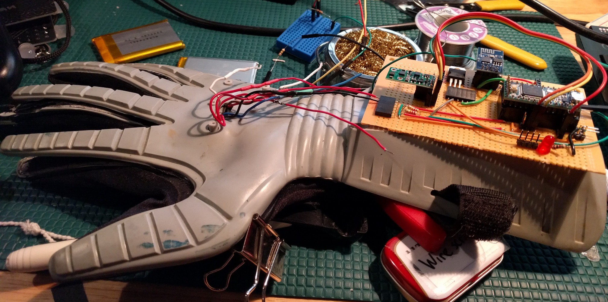
    The Power Glove electronics were removed, and the flex sensor wires were desoldered and lengthened for testing. Having previously decided on the main components, a piece of protoboard was loaded up with headers for the microcontroller (a Teensy 3), a WiFi module (an ESP-01) and the IMU (an AltIMU-10 v4). A 3.3V LDO was added to supply the power-hungry ESP, and voltage dividers were setup for testing the flex sensors. A USB cable with its wires broken out supplied power from an available USB port.

    The glove stripped of its electronics with new components mounted for testing

    Using a Pololu Arduino library for the IMU, motion data was easily captured by the Teensy, Gestures for the different finger positions had been designed previously, but for the time being, they would be eschewed in favor of simple open or closed states.

    Much to my dissatisfaction, the original flex sensors proved to be useless as they gave inconsistent readings. In comparison, the new flex sensors were spot on. The glove's index and middle fingers were cut open in order to replace the sensors. This was rather distressing as the work really took away from the look of the glove and would be difficult to repair. The next attempt (if any) to replace the sensors would have to be thoroughly thought through to prevent such damage. Here, you can see just how much degradation the old sensors had suffered over time.

    The innards of the Power Glove fingers, showing the new flex sensor and the degradation of the old ones.

    Read more »

  • Log Catch Up, Part One

    Nolan Moore03/12/2016 at 06:01 0 comments

    Welcome!

    This project was brewing in my mind, making small progresses here and there for months before I finally got the initial prototyping started and posted this project here on Hackaday.io. Having had so much time to review what's been done and figure out where I want to go, I hope to present to you, dear reader, full and concise accounts of said progress. For this initial log, I’ll be covering some of the ideas, planning and preparation that went into the project. It all started with...

    Crazy Ideas And Delusions of Grandeur

    If you’ve read the details in the project intro, you might know that I have some mad ideas for the Power Glove. Controlling anything and everything in order to rule the world might be a tad unrealistic for such a project, but mainly I've been working on it as a way to take my mind off of work and potentially transition onto something even greater.

    I knew that I wanted to modify the glove in such a way that the original aesthetic would be maintained. Sure it was a novelty project, but I wanted something clean I could show off, no hacked togetherness, no wires hanging out (excluding the prototypes of course). After opening it up and getting a good look at the boards and the limited spacing, I knew I would have to create something original to fit everything in. Preserving the boards was not an option.

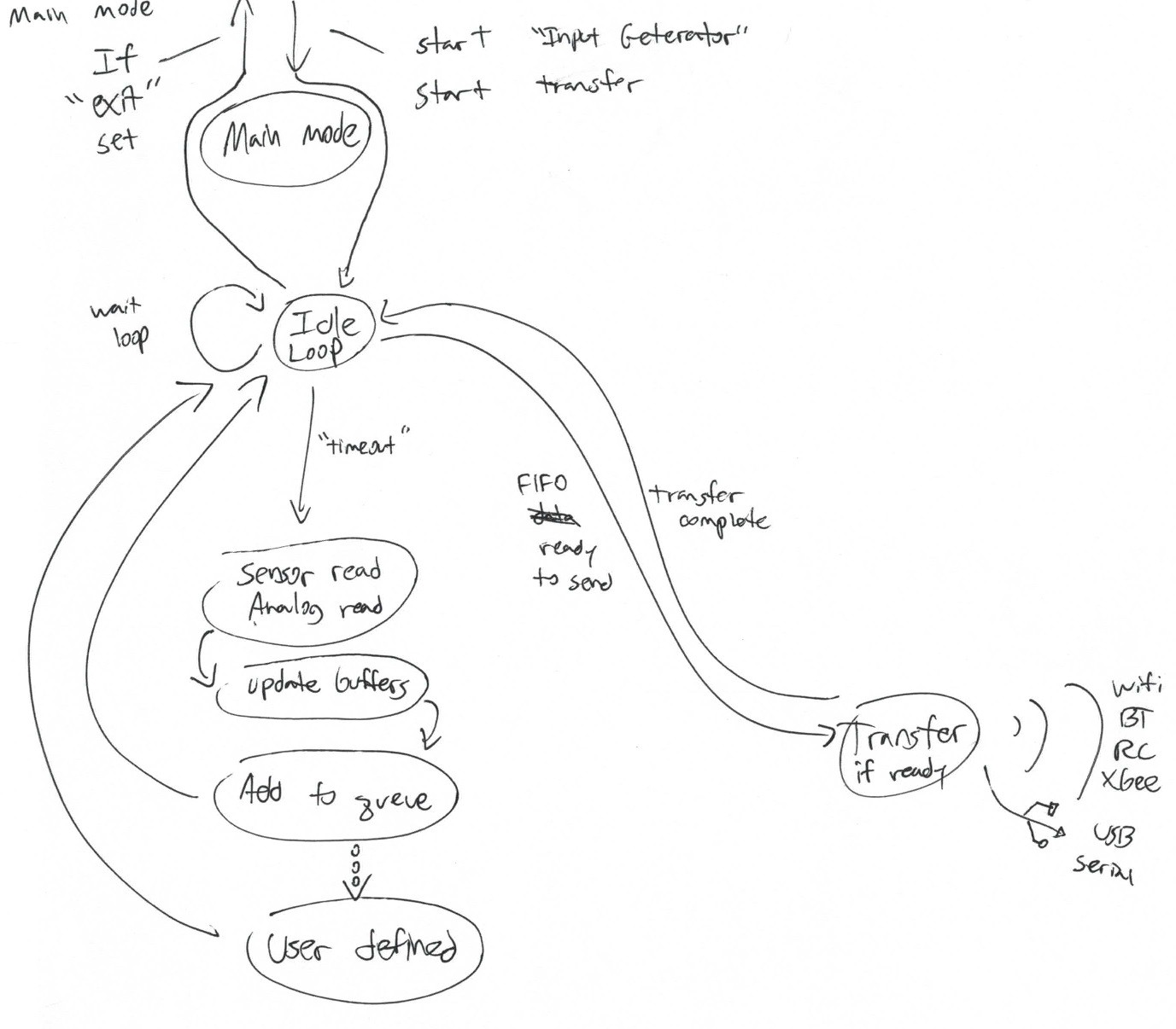
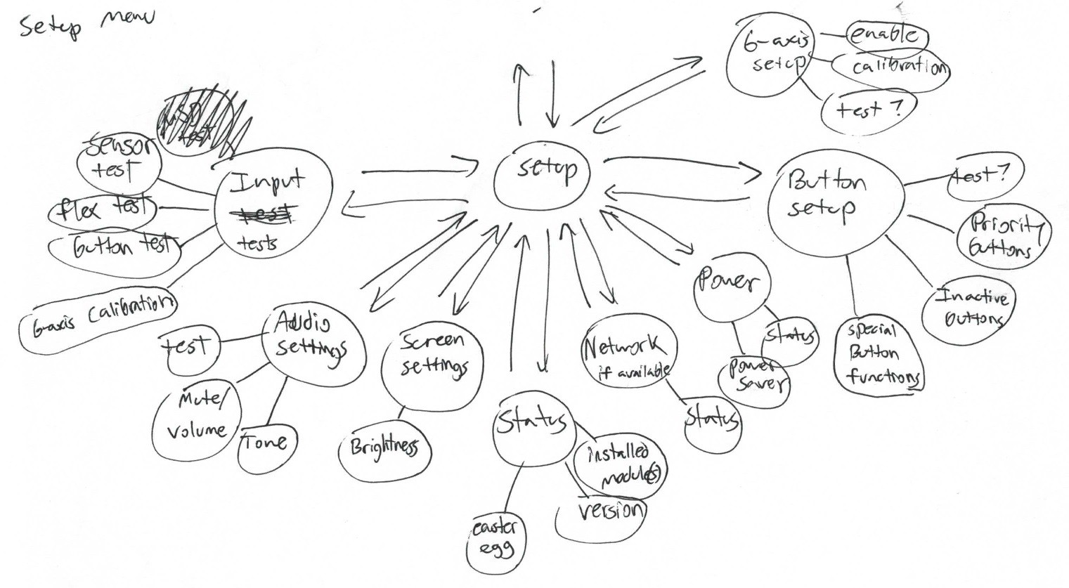
    I spent a large amount of time doing conceptual work for the project, putting together feature wishlists, drawing up ideas for gesture controls, creating state flow charts for the code... Much of this was lost after moving last winter, but some sketches remain.

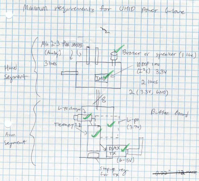
    Plenty of features were planned for the glove, and though many were scrapped for the initial prototype, they yet may be realized down the line. Some ideas just didn't make the cut due to design restrictions. One idea involved putting a Nokia phone display (later an OLED screen) in the sensor enclosure to give the user a menu for setting up the glove and monitoring data. Due to the glove's lack of visual feedback, this would have been quite nice, but the idea was put on hiatus in favor of retaining an unmodified look. Eventually, concepts gave way to requirements, and I started to put together what I would need to make the project a reality.

    Choosing the Main Components

    Main board

    For the microcontroller in the main board, I wanted to use the Arduino Zero design because it was the hip new dev board in town and it would give me some practice designing an ARM Cortex-M0+ device. As my programming had become a bit rusty, I hoped to forgo Arduino altogether and do some embedded programming instead. For prototyping purposes though, I decided to use what I had on hand, a Teensy 3, and a Teensyduino setup for ease of testing.

    Stemming from my work in quadcopters, the earliest idea for wireless communications was to use a DIY RC transmitter to control RC devices. The idea transformed into using interchangeable expansion cards to provide RC, Wi-Fi, Xbee, Bluetooth and other protocols by simply switching out the cards and configuration profile for the new device. This could be accomplished through something as simple as Xbee style boards. For now, the initial prototyping project (controlling a Parrot AR.Drone)would use an ESP8266 module, specifically an Adafruit Huzzah, for Wi-Fi communication.

    In order to keep the glove wire-free, a single cell LiPo battery and on-board charger would be used to power the system. A step-down/up converter would be used to provide 3.3V to the system. Pololu offers a wide range of switching regulators, making prototyping fairly convenient.

    Sensor board

    As many gamers now know, the Power Glove didn’t quite live up to the massive hype generated by commercials and a certain infamous movie. The TV receiver frame and the glove’s ultrasonic emitters would have to go. In their place, a 6 degree of freedom (6DoF) IMU would provide motion measurements. I had a couple 10DoF (a bit overkill really) AltIMU-10 boards from Pololu around for prototyping, but...

    Read more »

View all 6 project logs

  • 1
    Acquire parts
    • Power Glove
    • New replacement boards
    • Teensy, ESP8266, IMU, battery, FTDI cable or adapter, switch, LED, other parts
    • New flex sensors (optional, untested)
  • 2
    Disassemble Glove
    1. Remove arm strap
    2. Open keypad case, screws aside
    3. Open hand case, screws aside
    4. Desolder speaker, flex sensors
    5. Remove and save old electronics
  • 3
    Make Case Modifications
    1. Cut hole in bottom main case half
    2. Cut hole in top main case half
    3. Shave speaker mount down in top sensor case half

View all 9 instructions

Enjoy this project?

Share

Discussions

eball wrote 09/07/2018 at 15:25 point

received my boards today super excited to get started.   Love the silk screen on the board.  It's so bad.

My plan as well was to get it working with midi keep up the fantastic work and keep us updated

Thanks so much for providing an awesome project

  Are you sure? yes | no

Tom wrote 04/20/2018 at 15:39 point

Hi Nolan.  Be interested if you think this project could do something like Gest?

I am looking for something to replace a keyboard and mouse, but I appreciate your project may not cover that...

Gest is the Nintendo Power Glove you've been waiting for

https://www.wareable.com/wearable-tech/gest-is-a-hand-tracking-wearable-to-replace-your-keyboard-and-mouse-1883

  Are you sure? yes | no

Nolan Moore wrote 08/23/2018 at 16:35 point

Hi Tom! I'm really sorry that I've found your comment so late. In theory, this project is very similar to Gest, just far less refined and with much lower resolution. I'd actually like to get my hands on a Gest myself.

  Are you sure? yes | no

Nolan Moore wrote 08/24/2018 at 22:44 point

Hi Tom. I've finally got the boards up on Tindie! Here's the link: https://www.tindie.com/products/nolando/power-glove-uhid-prototype-boards/

  Are you sure? yes | no

eball wrote 10/28/2016 at 00:58 point

will you be selling theses boards. This is an absolutely fantastic project something I have been trying to build for years. But your custom boards are slick.  I have several power gloves just waiting for a reboot. 

People have been trying to make the power glove as awesome as it was supposed to be. Way back doepfer even made a midi interface.

Please make these boards availible and keep up the fantastic work

  Are you sure? yes | no

Nolan Moore wrote 10/31/2016 at 19:54 point

Hi eball, yes I am looking to make these boards available. Work's been keeping me from furthering this project lately, but I'm hoping to have some free time in the next month. I plan to put the remaining boards from the prototype on Tindie first before continuing development on the glove. 

Thank you for your support! 

  Are you sure? yes | no

Tom wrote 04/20/2018 at 15:37 point

Any updates on this, can't find it on Tindie?

  Are you sure? yes | no

Nolan Moore wrote 08/24/2018 at 22:44 point

eball, I've finally got the boards in my Tindie store: https://www.tindie.com/products/nolando/power-glove-uhid-prototype-boards/

  Are you sure? yes | no

eball wrote 08/27/2018 at 11:29 point

super awesome was doing some cleaning up and the power glove appeared. 

Will be ordering today

Thanks for all the hard work

  Are you sure? yes | no

Jose Ignacio Romero wrote 04/14/2016 at 04:38 point

The powerglove... it's so bad

  Are you sure? yes | no

Similar Projects

Does this project spark your interest?

Become a member to follow this project and never miss any updates