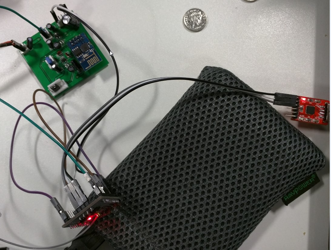
Actually got the 201 to flash, its certainly worth remembering that on these larger boards, GPIO15 needs to be pulled to ground in order to flash, as well as GPIO0, will need a quick tweak of the design to compensate for that
Currently the 201 is leeching off a project using the ESP-01 for power so I dont have to send off for the boards until I'm sure there isnt going to be another subtle difference like there was with flashing.

 unfoundbug
Discussions
Become a Hackaday.io Member
Create an account to leave a comment. Already have an account? Log In.
http://d.av.id.au/blog/esp8266-hardware-spi-hspi-general-info-and-pinout/
GPIO 0/2/15 should be pulled high/low according to the table in the link for the various modes. GPIO 0 and 2 have weak pullups which allows most people to get away without touching them, but it causes a lot of confusion for some who are using it connected to other things. GPIO2 according to that table appears to do nothing when low, but there's a whole bunch of other bootstrap options that are undocumented.
This is the full list:
GPIO15 Low, GPIO0 high, GPIO2 low = 2 = "Jump Boot".... no idea what this is...
Are you sure? yes | no
Having spent some time getting used to the ESP8266-01 the boot selection was something I was already aware of, GPIO15 having an internal pull up was definitely the thing that tripped me up. Thankfully the change is minor to compensate, a change from a SPST to a DPST
Are you sure? yes | no