-
Internet Success
07/06/2015 at 08:54 • 0 commentsApart from the webserver crashing overnight, it seems like the live control test went well :) Thanks to those who tried it out! Ustream on my tablet stops streaming after 3 hrs so I have to keep restarting it (if you see the stream dead, try again later).
-
LIVE
07/05/2015 at 13:24 • 0 commentsESP8266 Server: Link Removed
UStream: http://www.ustream.tv/channel/metalphreak (stream lags by about 15 seconds...)
Will stay up for the next 24hrs or until something breaks.
EDIT: Live site is now offline :) Thanks for playing.
-
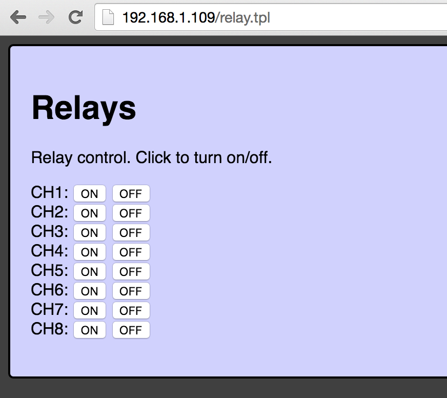
Webserver Works
07/05/2015 at 12:33 • 0 commentsGot the web interface up and running. No live status of the relays shown on the page yet, but remote turning on/off works perfectly :)
![]()
-
Front Panel Overlay and HTTP Server
07/05/2015 at 06:12 • 0 commentsI've been looking at options to put some kind of front panel overlay on the DIN rail enclosure. The best option I've seen so far that doesn't cost huge amounts of money is die-cut vinyl stickers. Looking at a service like stickeryou.com or stickerapp.com
Front panel dimensions and LED pipe/button locations have already been marked out in DXF format and converted to SVG for editing. Just need to dust off my photoshop skills and get something done...
In the meantime, I've been playing around with sprite-tm's esphttpd web-server code which works quite well. The actual code to control the relays on this via a web-interface are going to be quite simple. The challenge will be writing the html/css/js/ajax stuff to make it pretty.
-
Some videos of an assembled board...
06/26/2015 at 10:57 • 0 commentsJust sending simple 2 byte packets over a TCP socket for testing.
And just to see how many updates it can do over Wifi for kicks... Good thing these Omron relays are rated for millions of operations :)
-
Limited GPIO? Hardly.
06/26/2015 at 10:49 • 0 commentsThe first step when beginning this project was dealing with the limited IO pins on the ESP8266 modules. The ESP-07 and ESP-12 modules break out all of the useful pins. A number of pins needs to be pulled high or low during power on so it boots off the SPI flash memory (or bootloader).
GPIO0 - 10k pullup for boot mode - Bootload/Program button pulls this to ground on powerup/reset to enable update over serial. Doubles as a i2c clock pin
GPIO2 - 10k pullup for boot mode - also doubles as i2c data pin
If you gotta pull the pins up for boot select, might as well put anything needing a pullup on those pins ;) i2c is broken out to a header on this for future use
GPIO4 - 10k pullup - user switch
GPIO5 - user LED output
GPIO12/13/14/15 - hardware SPI pins for Data In/Out, Clock, and Chip Select
Note: GPIO15 has to be pulled low for both SPI flash/Serial boot modes. A 10k pulldown is fine for this as it is only the SPI clock line.
GPIO16 - unconnected by default - footprint for resistor connection to reset for sleep mode reset (not needed for this project).
Microchips MCP23S08 provides 8 GPIO pins over the SPI bus. Up to 4 of these can be connected to the same bus with a common chip select line. Each chip can be set to one of 4 addresses. So a total of 32 GPIOs is possible. Even better, the bigger brother MCP23S17 provides 16 GPIOs and can have up to 8 devices on one SPI bus (128 GPIOs!).
Some driver code for the MCP23Sxx chips is available on my Github - including support for multiple devices per SPI bus: https://github.com/MetalPhreak
So in summary, you can have 2 on-module GPIOs, (software) i2c and SPI with no issues. GPIO expanders provide plenty of addition IOs as required. The 2 on-module GPIOs can be used with the Microchip's interupt-on-change output pin to provide equivalent functionality to on-module GPIOs. Using the hardware SPI module for this is much better than the i2c versions, as you can buffer the data in the SPI module (which sends it at 10MHz), while you continue to do work with the main cpu (@80MHz). Software i2c ties up the whole device while it sends at sub 1MHz speeds.
ESP8266 DIN 8-Channel Wifi Relay Controller
8 channels of 10A 250V relays controlled over Wifi with an ESP8266 module at the core. Built in RS232-TTL level shifter for external devices