 Open Green Energy
-
1Step 1
1. Making The Transmitter :
![]()
![]()
![]()
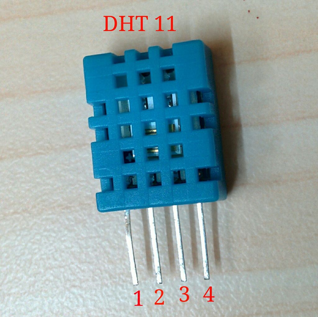
The transmitter module contain the various sensor for monitoring the weather.The DHT11 sensor is used for measuring temperature and humidity of the environment.It is good for 20-80% humidity readings with 5% accuracy and for 0-50°C temperature readings with ±2°C accuracy.
I ordered the Barometric Pressure Sensor( BMP085) and rain fall sensor from eBay to forecast more weather data.For the time being I am happy with only temperature and humidity.
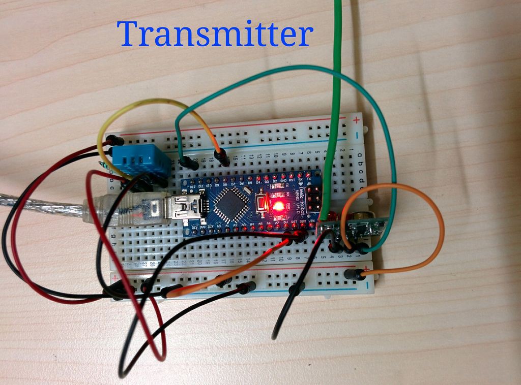
The weather data is measured by DHT11 ,processed by a Arduino nano/bread board arduino and transmit it wirelessly through a RF transmitter.
DHT11 Connection :
DHT11 sensor have 4 pins :
1->Vcc ,
2->Data ,
3->NC ,
4 ->GND
DHT11 -->ARDUINOVcc-->5V
Data-->D8
NC --> No connection
GND-->GND
Connect a 10K resistor between VCC and Data pin of DHT11
RF Transmitter Connection :The RF transmitter has 3 pins ( VCC,Data and GND).
RF Transmitter -->ARDUINO
VCC --> 5V
Data-->D11
GND-->GNDNote : Add a antenna in the RF transmitter to increase the range.click here
After connecting every thing, upload the Tx_code attached bellow
/*............................................................. Sending Multiple Variables Using VirtualWire. Transmitter Author: Rodrigo Mompo Redoliww http://controlrobotics.rodrigomompo.com Modified by deba168 from INDIA on 05/09/2014 ..............................................................*/ #include <VirtualWire.h> #include "LowPower.h" #include "DHT.h" #define DHTPIN 8 // what pin we're connected to #define DHTTYPE DHT11 // DHT 11 DHT dht(DHTPIN, DHTTYPE); int ledPin = 13; char Msg[30];// The string that we are going to send trought rf transmitter void setup() { dht.begin(); // initialing the DHT sensor pinMode(ledPin,OUTPUT); // VirtualWire setup vw_setup(2000); // Bits per sec vw_set_tx_pin(12);// Set the Tx pin. Default is 12 } void loop() { // Read and store Sensor Data int humidity = dht.readHumidity(); int temp = dht.readTemperature(); int f = dht.readTemperature(true); int hi_f = dht.computeHeatIndex(f,humidity); //heat index in fahrenheit int heat_index =(hi_f-32)*5/9; // convert heat index to celcius sprintf(Msg, "%d,%d,%d", humidity,temp ,heat_index); // Turn on a light to show transmitting digitalWrite(ledPin, HIGH); //LowPower.powerDown(SLEEP_250MS, ADC_OFF, BOD_OFF); delay(100); vw_send((uint8_t *)Msg, strlen(Msg)); vw_wait_tx(); // Wait until the whole message is gone // Turn off a light after transmission digitalWrite(ledPin, LOW); // put 5 mins sleep mode // As lowpower library support maximam 8s ,we use for loop to take longer (5mins) sleep // 5x60=300 //300/4=75 for(int i=0;i<75;i++) { LowPower.powerDown(SLEEP_4S, ADC_OFF, BOD_OFF); // Instead of delay(4000); //delay(4000); } } -
2Step 2
2. Making the Receiver :
![]()
![]()
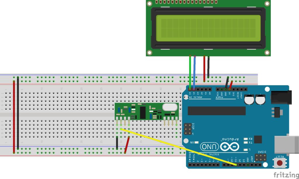
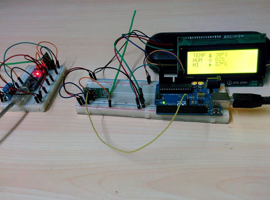
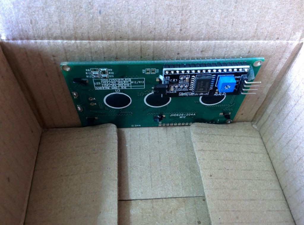
The receiver module receive the weather data by a RF receiver and it is processed by Arduino UNO .The processed data is displayed through a 20x4 char LCD display.You can also choose a 16x2 LCD also.The main reason for using a 20x4 char LCD is display is that I can display large number of weather parameters.
I add a I2C module to the LCD for reducing the number of connection with arduino (requires only 4 wires).
If you don't have a I2C module go to my tutorial on LCD tutorial for connection and example code.
LCD connection :
The I2C LCD have only 4 pins (GND,VCC,SDA,SCL)
LCD-->ARDUINO
GND-->GND
VCC-->5V
SDA-->A4
SCL-->A5
RF receiver Connection:
The RF receiver has 3 pins ( VCC,Data and GND).
RF Receiver -->ARDUINO
VCC --> 5V
Data-->D11
GND-->GND
Note : Add a antenna in the RF receiver to increase the range.click here
After connecting every thing upload the Rx_code attached bellow/*............................................................. Sending Multiple Variables Using VirtualWire. Receiver Author:Rodrigo Mompo Redoli http://controlrobotics.rodrigomompo.com modified by deba168 from INDIA on 06/09/2014 ..............................................................*/ #include <Wire.h> // use Wire library for protocol i2c (A4 = SDA & A5 = SCL) #include <LiquidCrystal_I2C.h> // use LiquidCrystal_I2C library for control LCD on i2c protocol #include <VirtualWire.h> // use Virtual library for decode signal from Rx module byte thermometer[8] = //icon for thermometer { B00100, B01010, B01010, B01110, B01110, B11111, B11111, B01110 }; byte droplet[8] = //icon for droplet { B00100, B00100, B01010, B01010, B10001, B10001, B10001, B01110, }; byte hi[8]= //icon for heat index { 0B00000, 0B00000, 0B10101, 0B01110, 0B11111, 0B01110, 0B10101, 0B00000, }; //(addr, EN,RW,RS,D4,D5,D6,D7,BL,BLpol) LiquidCrystal_I2C lcd(0x27, 2, 1, 0, 4, 5, 6, 7, 3, POSITIVE); //change the address as per your I2C module // Sensors int humidity=0; int temp=0; int heat_index=0; char MsgReceived[21]; int led = 13; //pin for LED void setup() { lcd.begin(20,4); // set up the LCD's number of columns and rows: lcd.backlight(); //backlight is now ON pinMode(led, OUTPUT); // VirtualWire // Bits per sec vw_setup(2000); // set pin for connect receiver module vw_set_rx_pin(11); // Start the receiver PLL running vw_rx_start(); lcd.begin(20,4); // initialize the lcd for 20 chars 4 lines, turn on backlight lcd.backlight(); // finish with backlight on lcd.createChar(1, thermometer); lcd.createChar(2, droplet); lcd.createChar(3,hi); lcd.clear(); // clear the screen } // END void setup void loop() { uint8_t buf[VW_MAX_MESSAGE_LEN]; uint8_t buflen = VW_MAX_MESSAGE_LEN; //Taking the data from the control base if (vw_get_message(buf, &buflen)) { digitalWrite(led, HIGH); delay(100); int i; // Message with a good checksum received, dump it. for (i = 0; i < buflen; i++) { // Fill Msg Char array with corresponding // chars from buffer. MsgReceived[i] = char(buf[i]); //Serial.print(MsgReceived[i]); } sscanf(MsgReceived, "%d,%d,%d",&humidity, &temp,&heat_index); // Converts a string to an array digitalWrite(led, LOW); lcd_display(); memset( MsgReceived, 0, sizeof(MsgReceived));// This line is for reset the StringReceived } } void lcd_display() { lcd.setCursor(1,0); lcd.print(" WEATHER STATION "); lcd.setCursor(4,1); lcd.print("TEMP"); lcd.setCursor(9, 1); lcd.write(1); lcd.setCursor(11, 1); lcd.print(temp); lcd.write(0b11011111); lcd.print("C"); lcd.setCursor(4,2); lcd.print("HUM"); lcd.setCursor(9, 2); lcd.write(2); lcd.setCursor(11, 2); lcd.print(humidity); lcd.print("%"); lcd.setCursor(4,3); lcd.print("HI"); lcd.setCursor(9, 3); lcd.write(3); lcd.setCursor(11, 3); lcd.print(heat_index); lcd.write(0b11011111); lcd.print("C"); } -
3Step 3
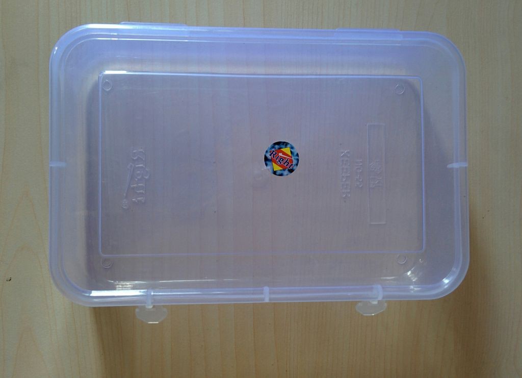
3. Making the Enclosure for Transmitter :
![]()
![]()
![]()
![]()
![]()
I used a plastic box for transmitter module enclosure.
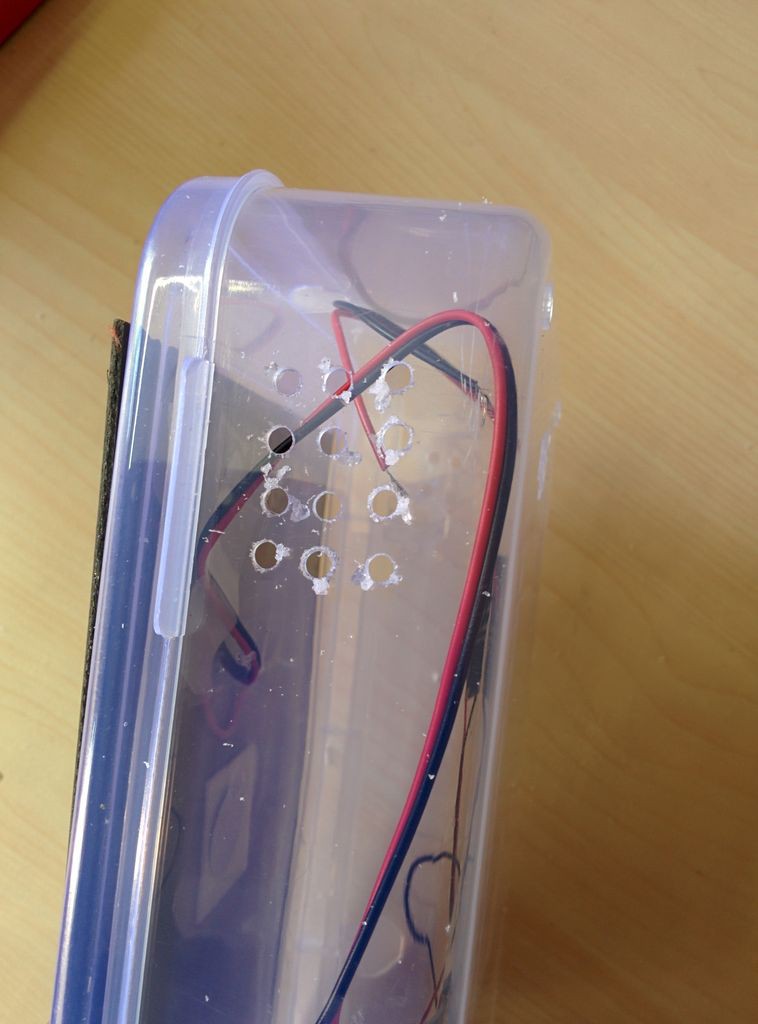
Make a hole in the top side of the plastic box for inserting wire from the solar panel.
Make small holes in the side wall (opposite face) for ingress of fresh air ( to measure the accurate data ).see the pics.
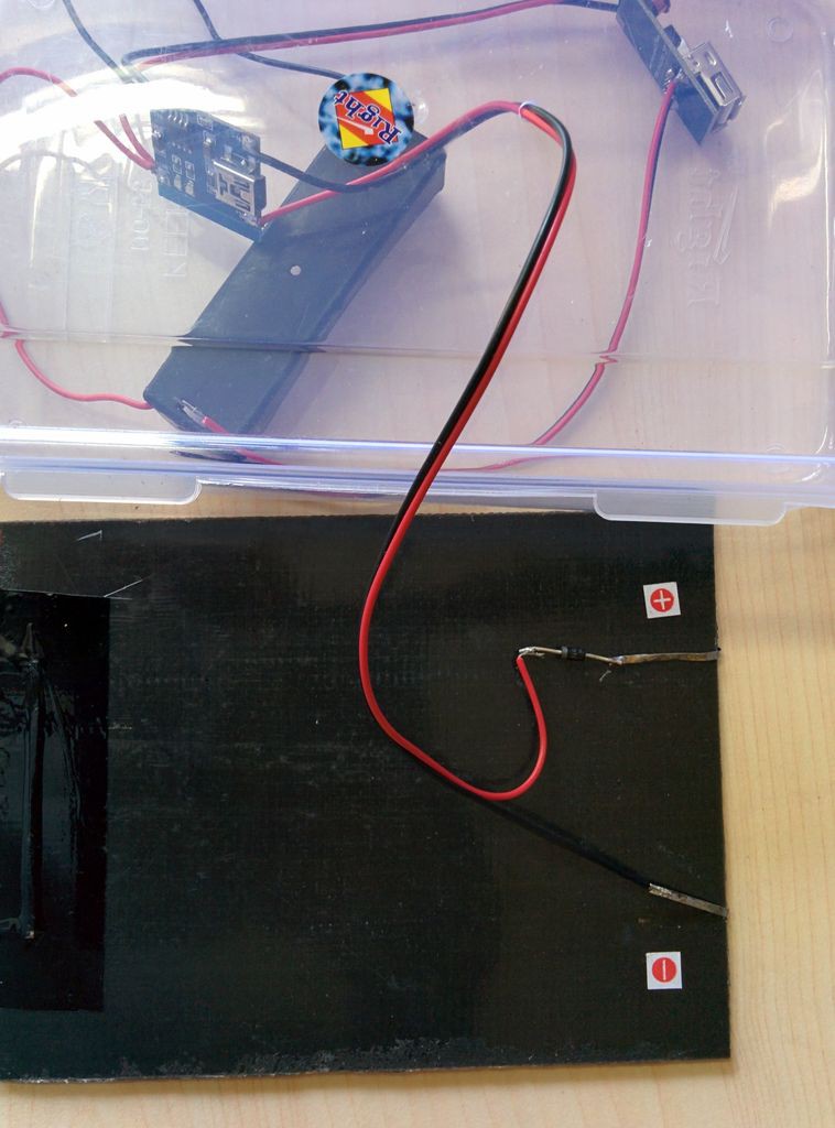
Place the charging circuit (made earlier) inside the box.
Take out the wires from li ion battery charger (IN+ and IN-)
Solder the positive terminal of solar panel to the positive terminal of diode and negative terminal of the diode to the red wire from the the charger.
Solder the black wire to the solar panel negative terminal.
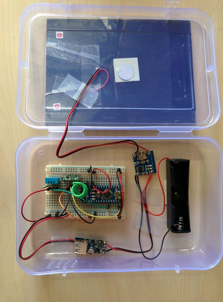
For mounting the solar panel and battery holder I used skotch mounting pad.The mini bread board have inbuilt pad to stick.
Use tap to stick the wire firmly.
Connect the 5V (+) and GND (-) terminals of boost converter to the bread board red rail(+) and blue rail (-) respectively.
To test it expose to sunlight ,you will see red led in all (arduino,boost converter,charging) the boards will glow. -
4Step 4
4. Making the Enclosure for Receiver :
![]()
![]()
![]()
![]()
![]()
![]()
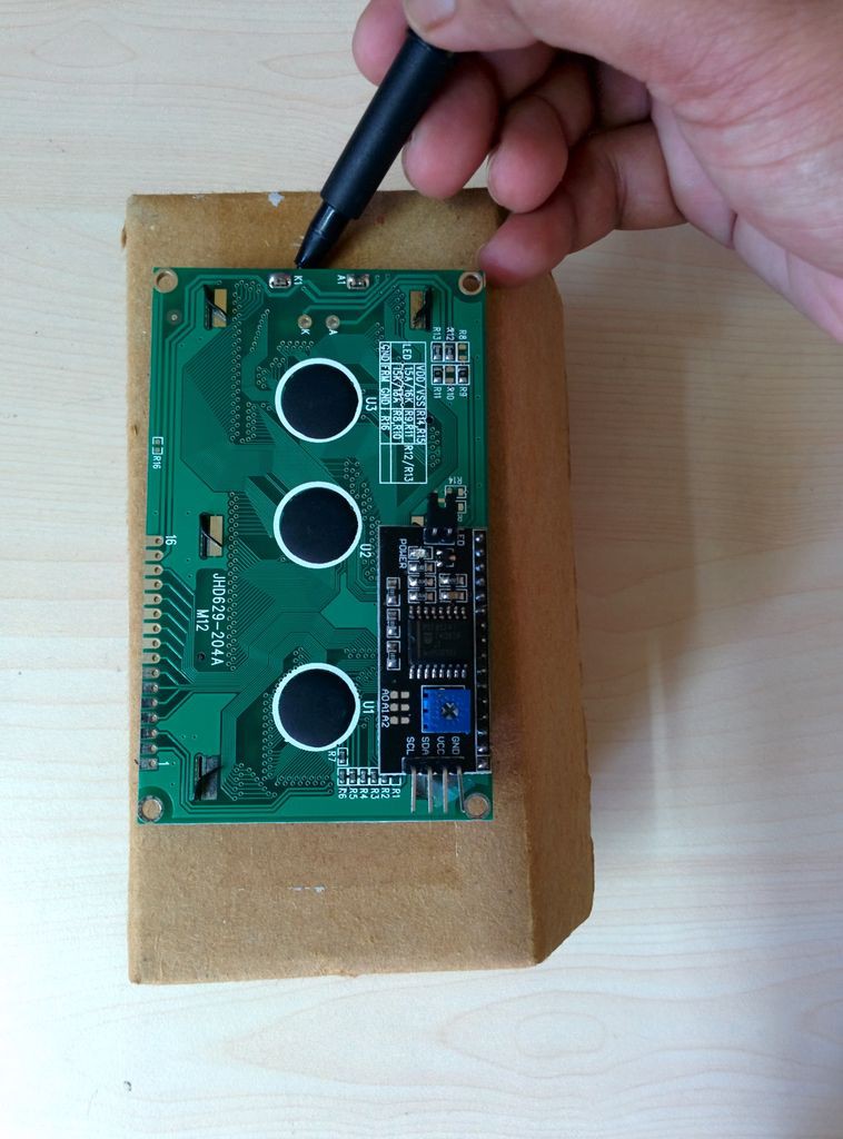
The receiver enclosure is card board box.
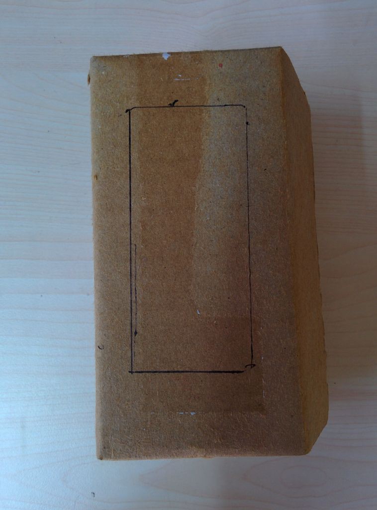
Mark the outline of lcd by using a pencil or marker.
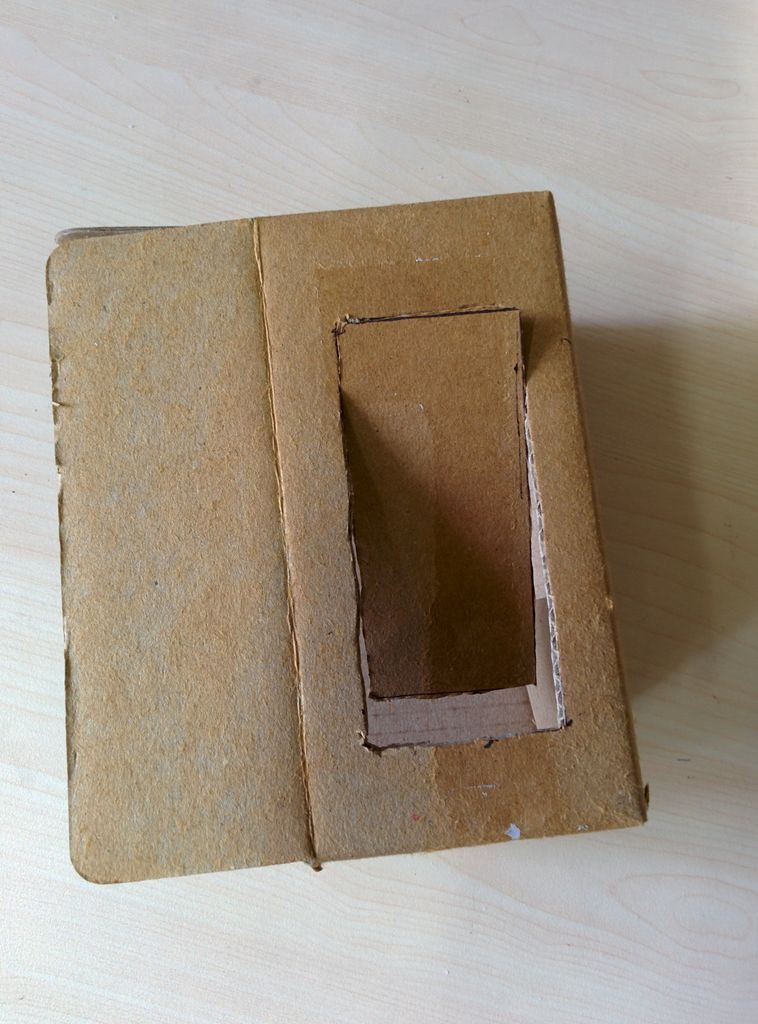
Cut the marking portion by using a hobby knife.
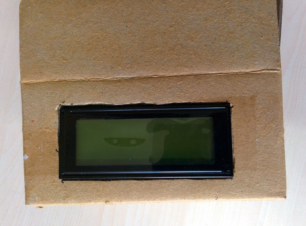
Insert the lcd in to the cutting portion of the box.
Hard gue on the back side of the lcd to hold it firmly
Place the bread board receiver module prepared in the previous step.
I use a 12V dc adapter for powering the arduino uno.Make a hole in the back side of the card board box for inserting the DC adapter cable.
SOLAR POWERED ARDUINO WEATHER STATION
A solar powered Arduino Weather Station to help the farmers


Discussions
Become a Hackaday.io Member
Create an account to leave a comment. Already have an account? Log In.
Hi I only have I2c lcd is it possible to use it and if so could you please explain code change.
Thanks
Bill
Are you sure? yes | no