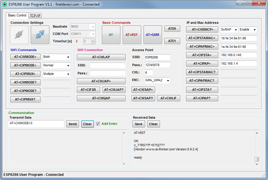
The socket for ESP8266 is connected to the FPGA only, so we need to connect the ESP to UART for testing first.
This is just a "wiring" code for FPGA, creates wires from ESP to UART pin of FT2232H.
// ICEd UART to ESP8266
// What it does: connects FTDI channel B pins to ESP8266 UART

module top(
	// RGB LED
	output LED_R,
	output LED_G,
	output LED_B,
	// Small SMD LED (green)
	output LED_small,

	//
	output ESP_TXD,
	input ESP_RXD,
	output ESP_RESET,

	input ESP_GPIO0,
	output ESP_GPIO2,

	// FTDI FT2232H Channel B
	input BDBUS0,
	output BDBUS1
           );

	assign LED_R = BDBUS0;
	assign LED_G = ESP_RXD;
	assign LED_B = 1'b1;

	assign ESP_GPIO2 = 1'b1;
	assign LED_small = ESP_GPIO0;

	assign ESP_TXD = BDBUS0;
	assign BDBUS1 = ESP_RXD;

endmodule // top
Sure pin constraints too, then load the FPGA, and ready to test.First test worked - the only issue was wrong baudrate setting!
 Antti Lukats
Discussions
Become a Hackaday.io Member
Create an account to leave a comment. Already have an account? Log In.