EK
EK-
Workshop @ Hackaday Hardware Superconference
10/24/2015 at 00:55 • 0 commentsI'm giving a workshop at the Hackaday Hardware Superconference!
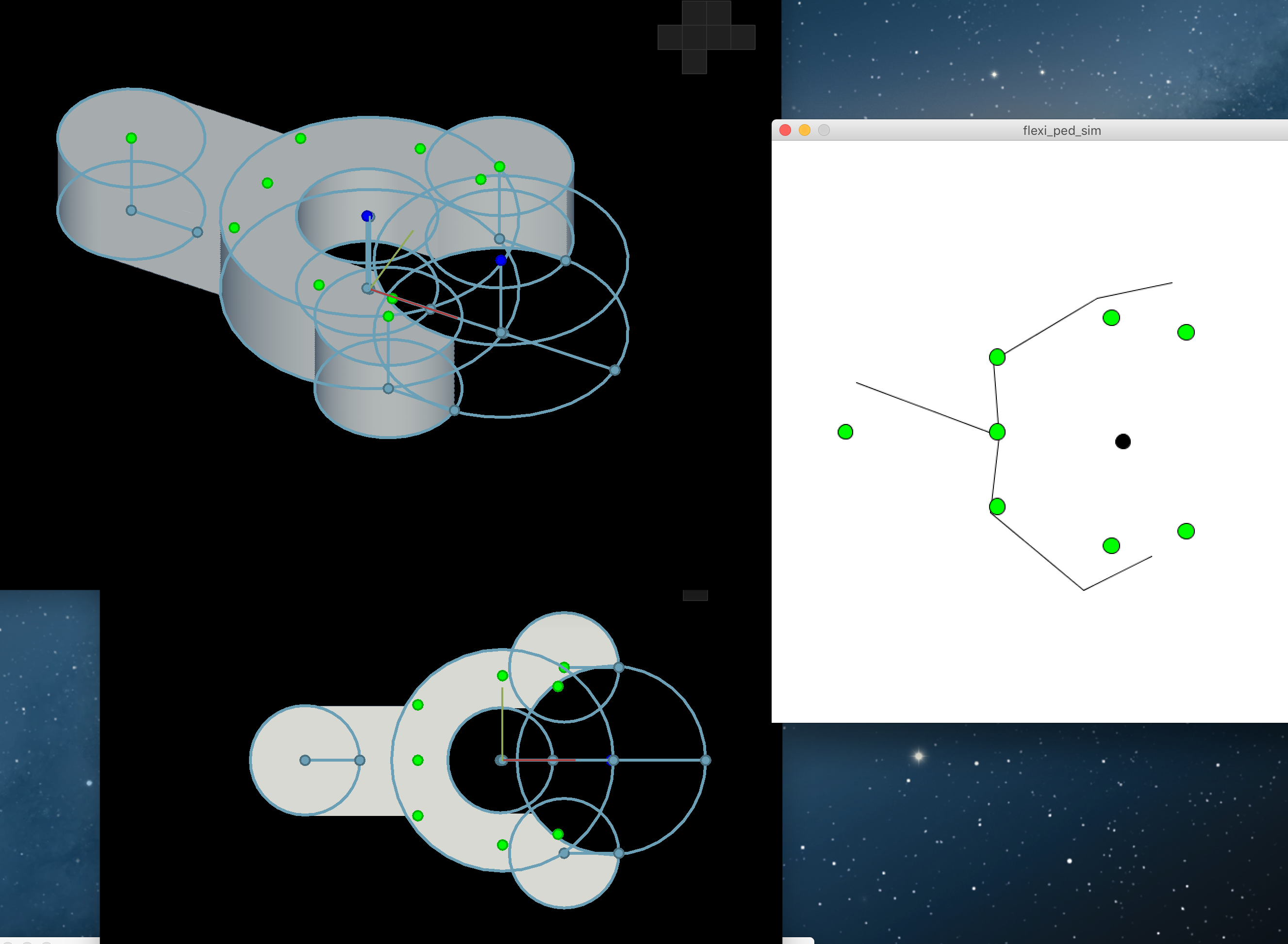
Designing with Antimony for use with custom skeleton-physics simulation
![]()
Learn how to design parametric models in Antimony to make your prototyping process faster by spending less time tinkering your design with each iteration. Create complex geometric sculptures in Antimony with scripts. We will then dive into selecting key points on the geometry for use in a custom-made skeleton based physics simulation. This is helpful if you are using new materials for fabrication and need to develop your own way to simulate how it will behave under certain forces.
If you have not heard of Antimony yet, check it out! It's developed by Matt Keeter. During Fab Academy 2015 all of us students used it a lot- I became addicted to it! =)
Working on the details this weekend- will post with updates! Hope to see you there!
-
Started Studio[Y] at MaRS Discovery District
10/24/2015 at 00:38 • 2 commentsHi everyone!
If you were following this project throughout the Hackaday Prize, and maybe before that with Fab Academy, you might have noticed that there were not so many updates once September rolled around. Read on for the details!
Back in September I started a fellowship called Studio[Y] at the MaRS Discovery District, Canada's leading innovation hub. It is with a cohort of 25 young leaders.
The fellowship is focussed on social entrepreneurship. It's a great opportunity to bring my technical knowledge here and mix it with questions such as:
- To what end?
- What impact will it have?
- What does the system look like- Who are the key players?
- Where are the leverage points?
Usually when we are prototyping robots, or our projects, if we are not on a team, it can be an oversight to evaluate the problem and what impact we want to have, as a whole.
I've been learning new lessons each day. It's valuable to be able to shift mindsets to evaluate problems through different lenses. Learning what questions to ask to become more knowledgable about the problems. As well as tools to utilise for further investigation.
There's a self-directed phase of the fellowship starting at the end of November. I still love this project, but we will see what happens at that time. I definitely have to refine the problem definition and evaluate the system more in depth. Either way, a better name would definitely be required. ;)
You can follow my instant updates @RobotGrrl
If you are still reading updates about this project and still interested, thank you for hanging around!
-
Field test: Cleaning shores of debris w/ RDAS v0.5
10/24/2015 at 00:17 • 5 commentsMini field test showing how RDAS v0.5 can move some debris on the shores of this beach! What a rush it was to see the bot working in action out in the field (and it was raining a bit too)! Check out the video
Great to have the ducks there while I was testing the bot. It definitely gave a broader scope to why I'm trying to make these robots.*Note: This was recorded around September 10. The development of the prototype has advanced since then.
-
(Accidentally) Breaking a robot while recording — Update of RDAS v0.5
10/24/2015 at 00:15 • 0 commentsTransformation from RDAS v0.4 to v0.5 was quite drastic! Here are the details on what has changed. Check out the video
I'm excited to improve the magnetic coupling piece.*Note: This video was recorded back around September 10. The development has progressed since then
-
RDAS Field Testing - Trials 1 & 2
10/24/2015 at 00:13 • 0 commentsAn overview of what RDAS is, the type of terrain a locomotion module should be able to work on, and video clips from field tests 1 & 2. Check out the video
*Note: This was originally created on September 2. The prototype is a bit farther along now.
-
Quick update - "Sometimes by almost starting over"
09/01/2015 at 14:11 • 3 commentsLast week I took RDAS out on a few field tests to try it on different terrains and see how it would work in the real world.
There will be a video up soon showing how exactly it behaved.
Since then I've been improving how it all works together, made a few modifications and tested again.
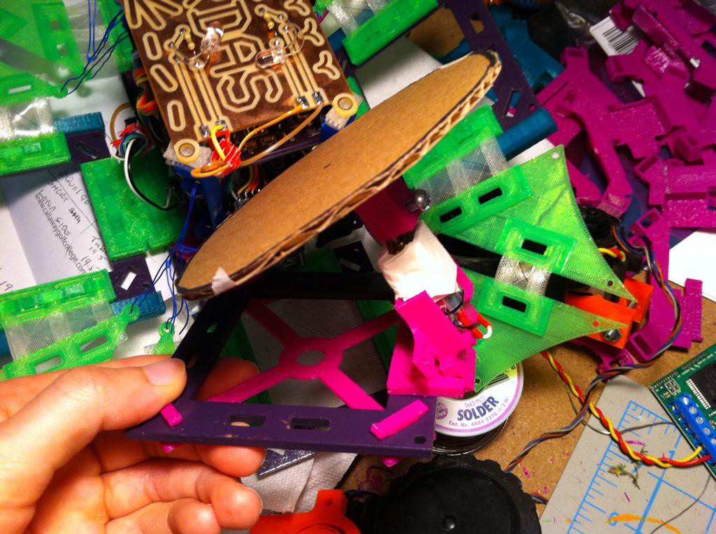
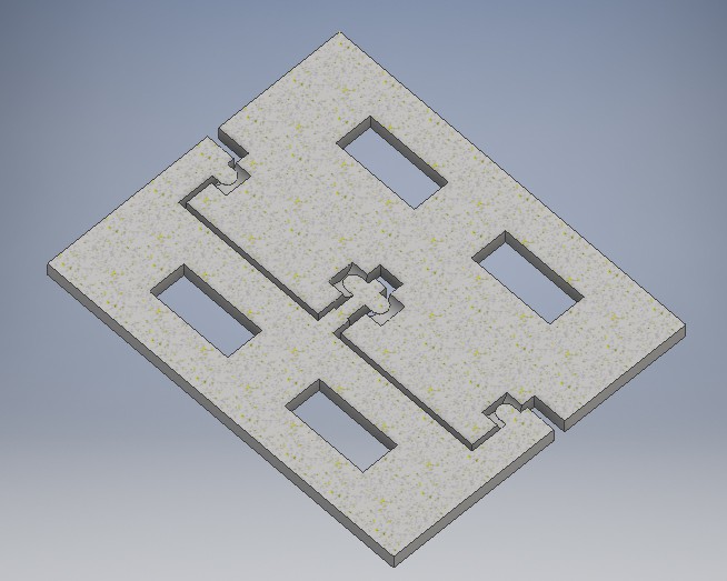
Luckily with these tests and rapid prototyping it makes it fast to evaluate how the bot works and improve it — sometimes by almost starting over. Here's a new idea that is being prototyped:
![]()
Now back to the prototyping! Have some laser cutting to do today, excited!
-
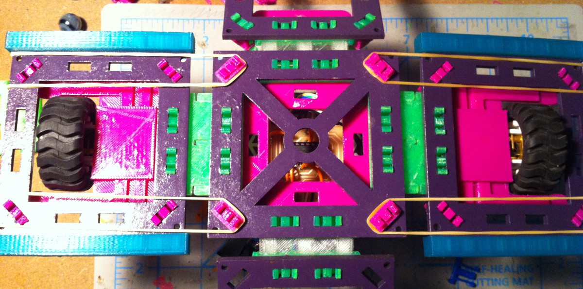
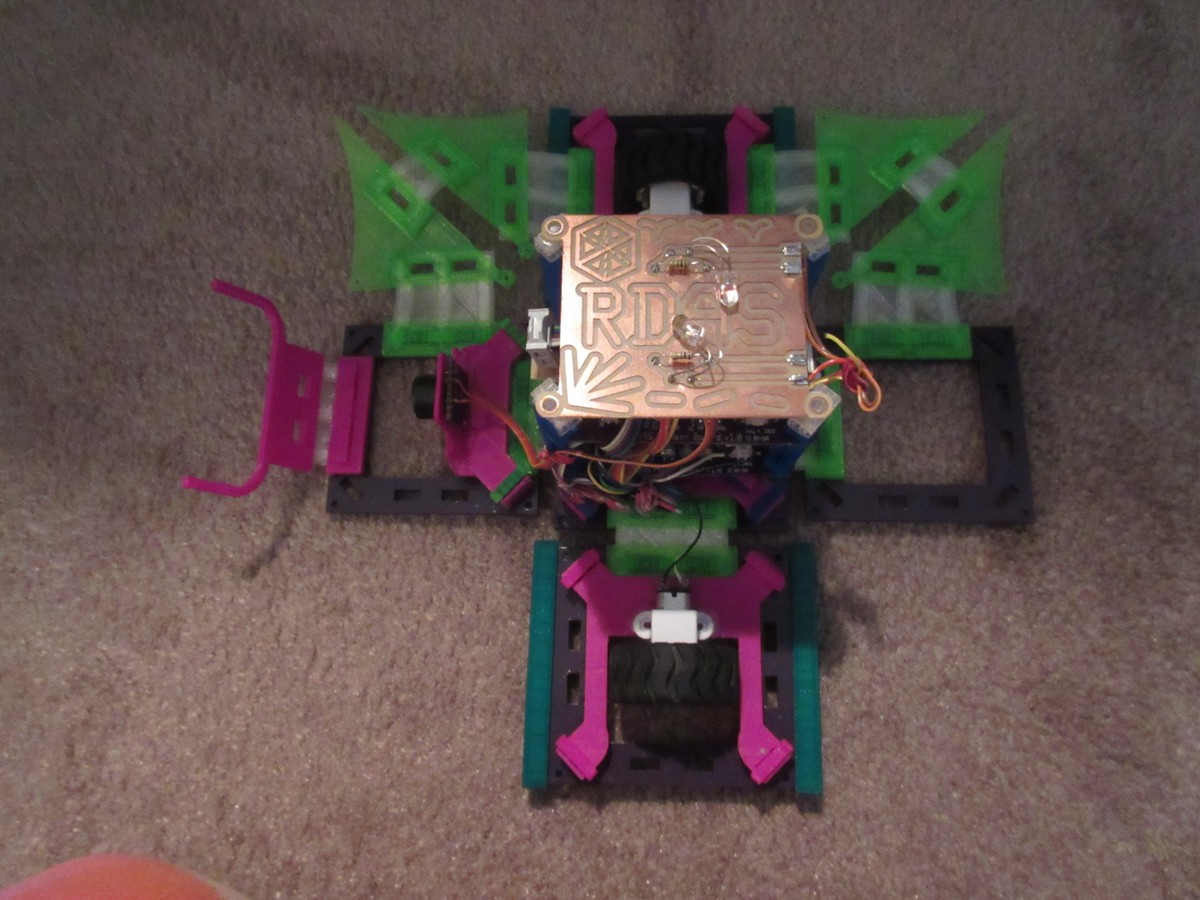
Wheel Improvements (with 4 Elastic Bands!)
08/27/2015 at 13:22 • 0 commentsHere are some improvements that were made to the bot to fix the issues diagnosed previously.
![]()
Read more to see all the details
Rigid Hinges
The hinges do not need to move past 90 degrees. I decided to switch to a rigid hinge because it will provide more stability to the sides with the motors, which will be necessary for navigating its environment.
Here is the new design. It's printed in place without supports, the hinge cannot be sepparated:
![]() Here is what it looks like on the bot:
Here is what it looks like on the bot:![]()
![]()
Here is an initial video of this test, RDAS working on carpet:
I made a mistake with this test. Didn't account for the 'grain' of the carpet. So the bot did not actually work in all directions on carpet. Time to fix the next thing.
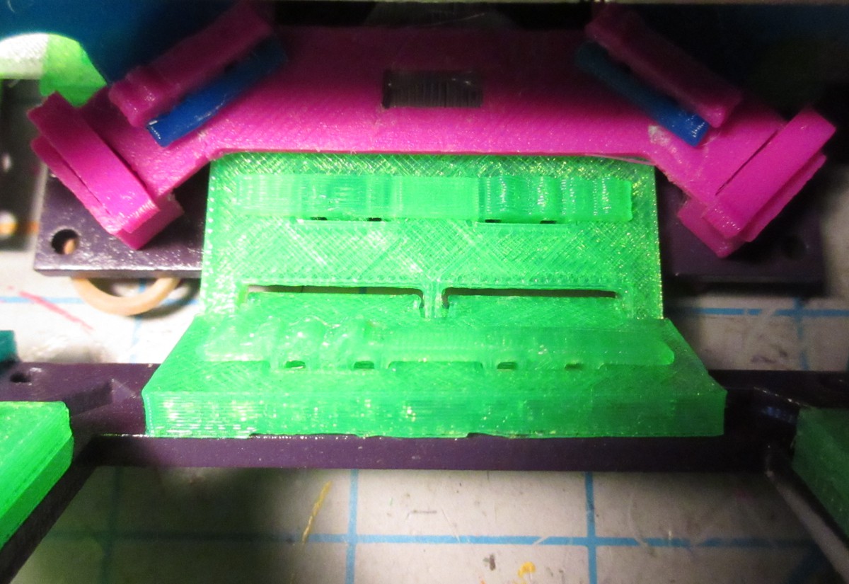
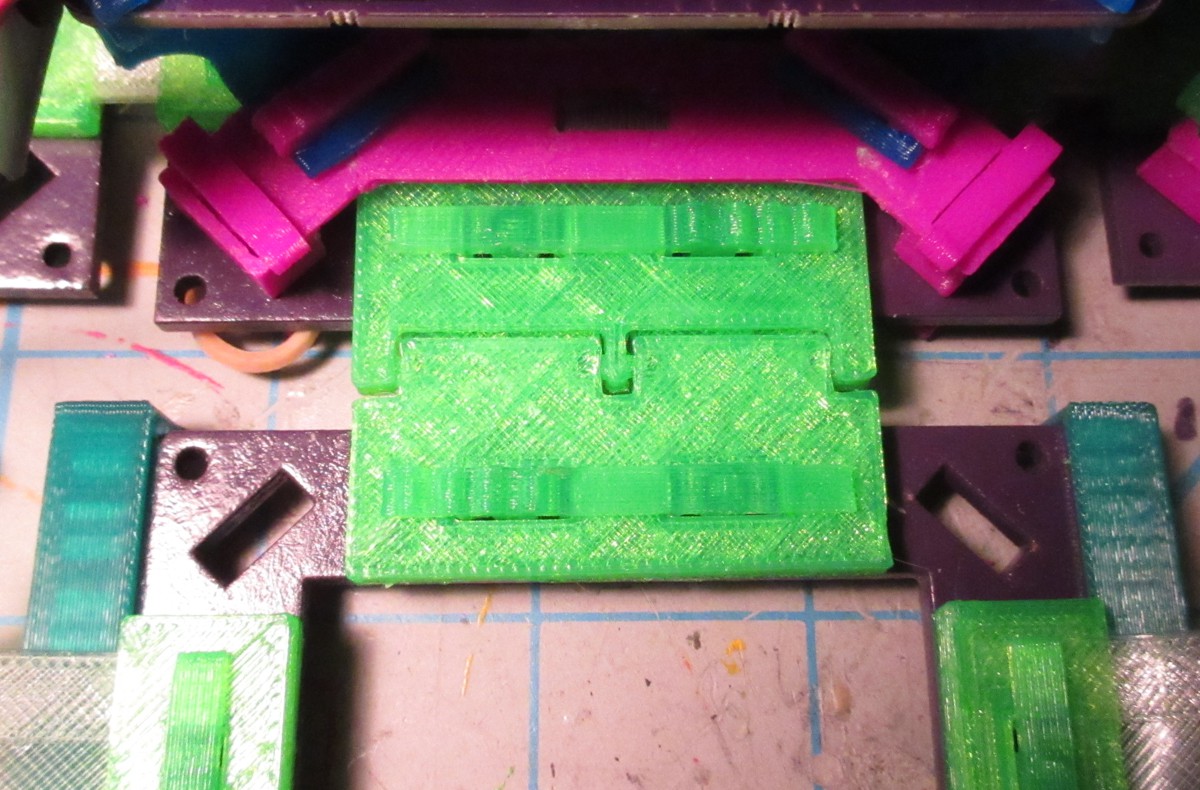
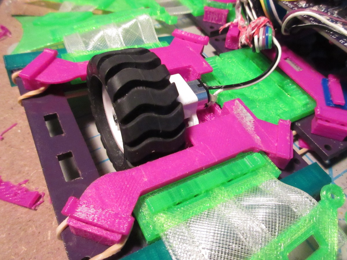
Motor Mount Piece
Currently the piece that the motor is mounted on is a flat piece. It could have an indent that would drop the wheel down more. This would help with it being able to not drag the rails and sides along the ground, because the amount that the wheel is extending is raising it up.
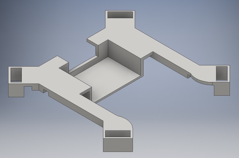
New designed piece (printing it with supports is necessary):
Iterations that it took to get here:![]()
Here it is with motor on it and attached to side:![]()
![]()
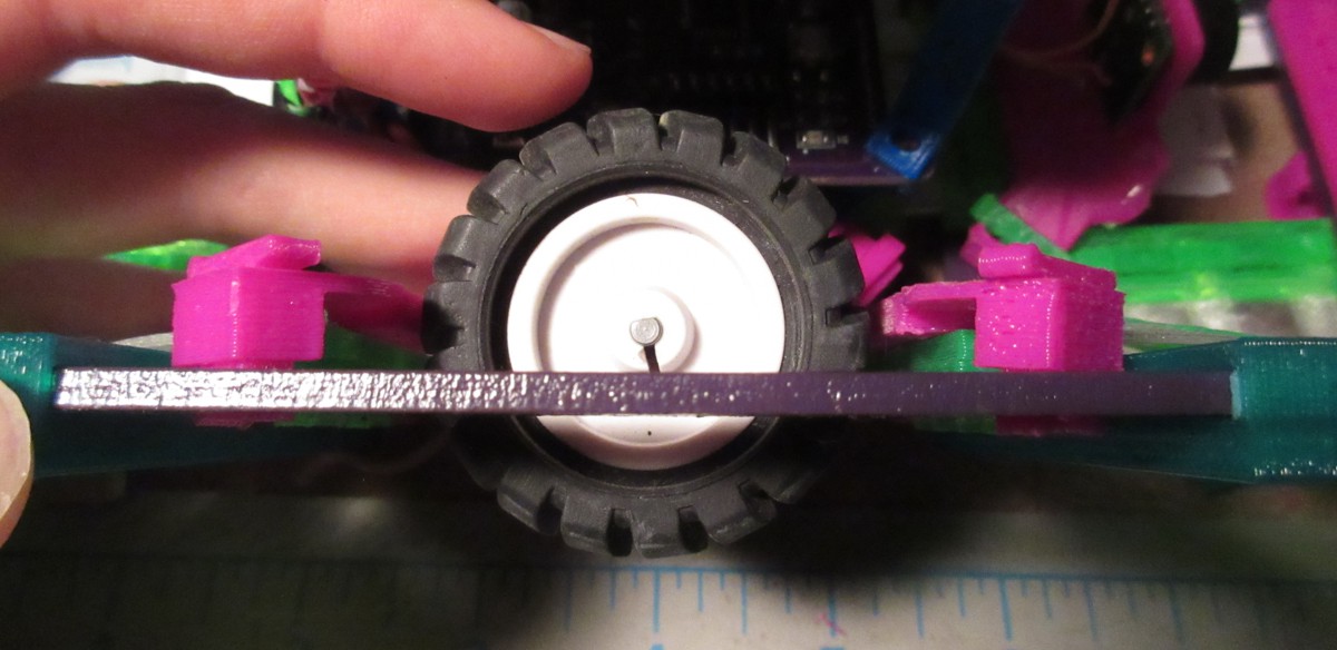
Here is how far the wheel extends now:
![]()
The edge of the wheel extends past the rails now, which would be a problem in an actual CubeSat deployer.
One way to fix this would be to have the motor initially compressed using springs while in the folded position. Burn wire would be holding this in place. After being deployed, the burn wire would be removed (by burning it), and the motor would snap into position from the force of the springs. It would be locked to this height, and would not be able to move back up.
For the purposes of this prototype and moving along, I'm going to focus on other aspects of the bot before fixing that.
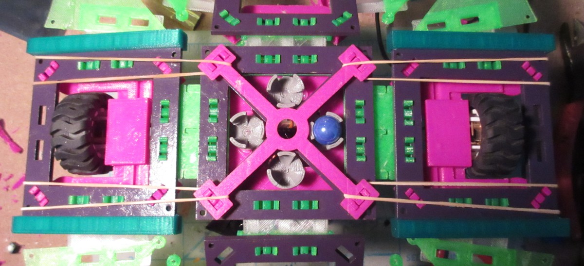
Elastic Bands
How to make the side pieces with the motors snap down, but also be able to be folded up? I tried a few different things, like with springs, clothes peg springs, but finally settled on four elastic bands.
The bands loop around the last snap of the mount piece. They go underneath the side to loop around snaps on the base that are used for the vertical holder.
Here was the first try at this:
![]()
The problem with this was the bands kept flying off of the simple knobs around the snaps. Improved this by making a piece that attaches to all snaps:
![]()
In action:
Next Steps
Now, the bot works in all directions on the carpet. Time for more difficult terrain. Going to have the first field test with the bot and evaluate what should be further improved.
One of the core tasks that I think this RDAS: Drive module would be a plow. It could push dirt / mud / gravel around, and build piles or help clear paths with it.
While doing the field tests will have this goal in mind. Preliminary check of the robot prior to the test: -
Diagnosing the Wheel Problem
08/27/2015 at 02:07 • 8 commentsIn the video showing the latest prototype of RDAS (v0.4), you might have wondered why I had to hold down the sides of the robot for it to move. Especially when it's supposed to be hands free -- it just seems contradictory! Time to investigate further.
![]()
Read more for explanations of the observations and the next steps.
Observations
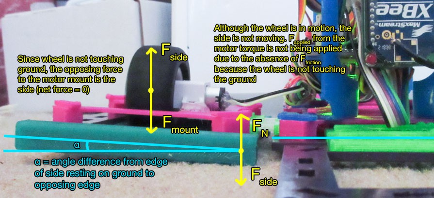
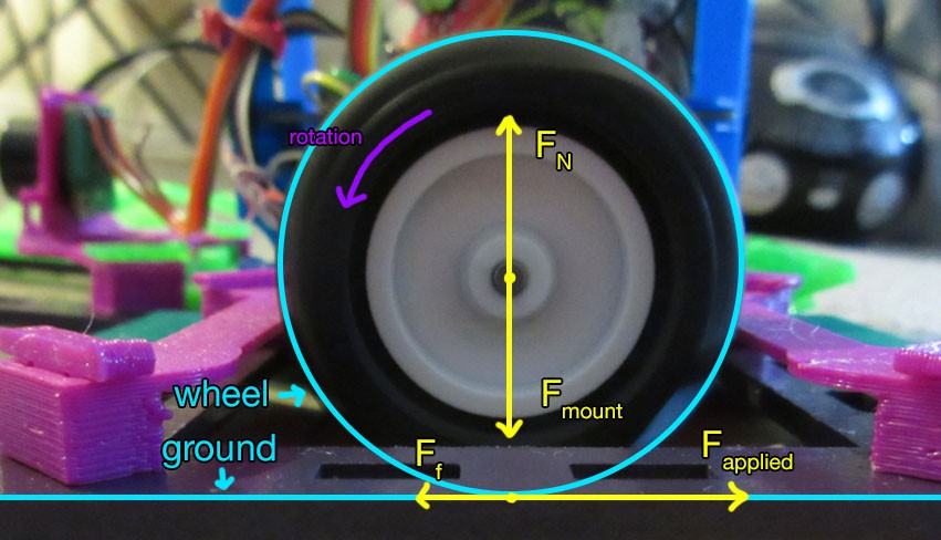
1. Wheel not touching the ground
![]()
The wheel does not always touch the ground. If the base is not lifted high enough -- or if it is sinking in to carpet, then the edge of the side becomes in contact with the ground. This prevents the wheel from gaining direct contact with the ground, which means the torque from the spinning motor is not being applied. It isn't going anywhere because there's no friction force from the ground to overcome!
Here is what it *should* be like:
![]()
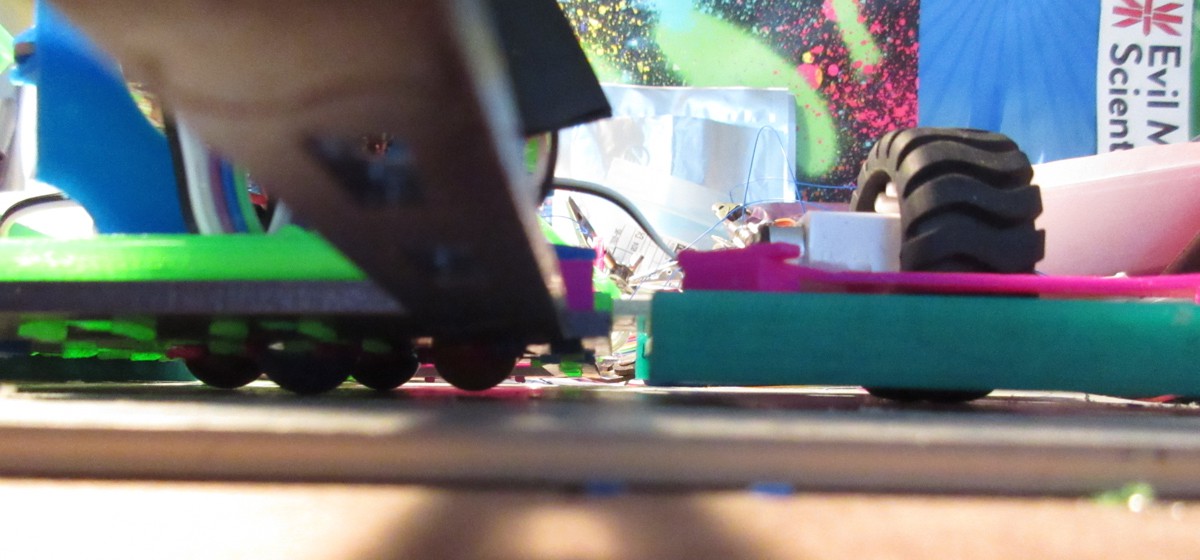
Seemingly the only time this ideal situation occurs is on the lab desk:
![]()
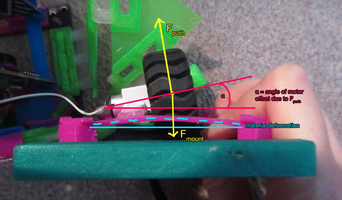
2. Large material deformation when force applied to wheel
![]()
When pressing on the wheel, the mount is resisting by trying to retain its original shape, which is perpendicular to the side. There is some stress in the material- the hot glue sticking the motor to the mount, and also the mount deforming. There's a large deformation along the side of the piece.
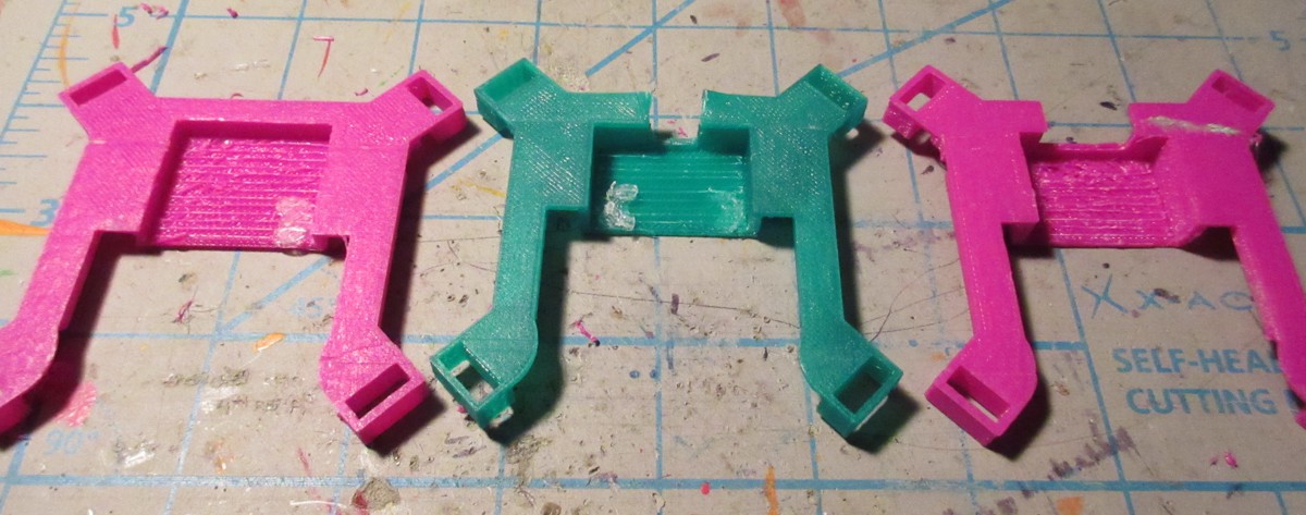
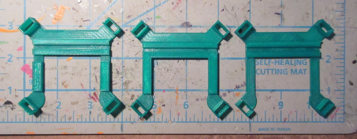
This is an issue because if the above problem was remedied, then there would still be this problem. Making the beam thicker would help alleviate it. I tried three different designs:
![]()
The one in the middle worked best.3. The motor sides should not be able to unfold > 90 degrees
The flexible hinge that attaches the sides to the main base can move to whatever angle- both beyond the ground and also to fold up. The motors would never need to go beyond 90 degrees.Next Steps
After diagnosing all of these issues, here are the things I need to fix:
1. Make the motor sides flush with the base so the wheels are being pushed down onto the ground
2. Move the motor down so it can extend past the edge of the side more
3. Make the motor sides only unfold to 90 degrees, BUT still be able to fold upTime to start fixing it, v0.5 here I come
![]()
Special thanks to Reagan for looking over the diagrams
-
RDAS at the lake
08/17/2015 at 20:19 • 0 commentsHere's a video I made showing the latest version of RDAS. Check it out:
It was nice to take the robot out in the field.
One of the things you might notice in the vid is that I have to push down on the sides of the robot so it can move. The reason why is because the extension piece that the motors are attached to tends to flex, so when the motors are trying to push onto the ground, it ends up flexing. This means that the wheels don't have good contact.
In the next revision I'll be evaluating if making the extension piece stronger will help. If it doesn't, I'll add a similar locking mechanism to a folding table. It would extend from the inner structure to the motor panels.
There are also new diagrams up in the project details. These give a clearer overview of my idea. Please check them out if you have time!
-
Video update: Adding on the extension panels, getting ready for motors!
08/16/2015 at 15:58 • 0 comments
Rapidly Deployable Automation System
Unfolding CubeSat rover. Mission: construction on Mars & re-construction after natural disasters on Earth. Tele-op Headband control.
 Here is what it looks like on the bot: