-
Challenge Accepted
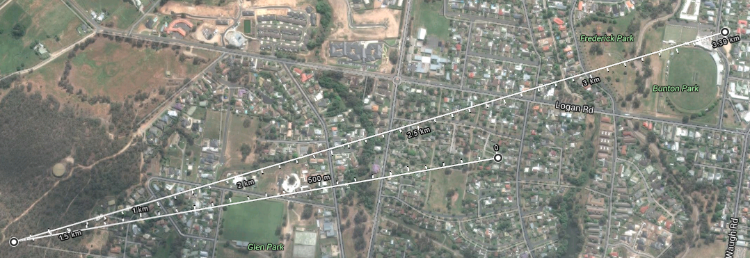
09/18/2015 at 03:25 • 0 commentsDue to a pending size increase for my family, it seems we will be moving to a new house. And with it comes some additional challenges for the WiFi bridge.
![]()
We aren't moving all that far, only a couple of minute drive into a much larger (and maker friendly) house. But it does increase the distance of the bridge quite significantly. Not being one to quit when things suddenly get interesting, I have decided to add a repeater node on a nearby hill since I will no longer have line-of-sight to my mother-in-laws house.
There are some additional challenges this time that I can forsee:
- The additional 4.75(ish) km of round-trip range.
- Powering a repeater 24/7 with no power supply (Solar FTW!)
- Protection of the repeater from vandals
- Antenna design (good quality directional antennas)
- Regulations!
More updates pending as I tackle the issues!
-
Barometric Pressure Sensor
09/07/2015 at 02:55 • 0 commentsHaving remembered I had a BMP085 pressure sensor breakout in my shed from an old project, I set about adding it to the Einstein box's growing list of sensors.
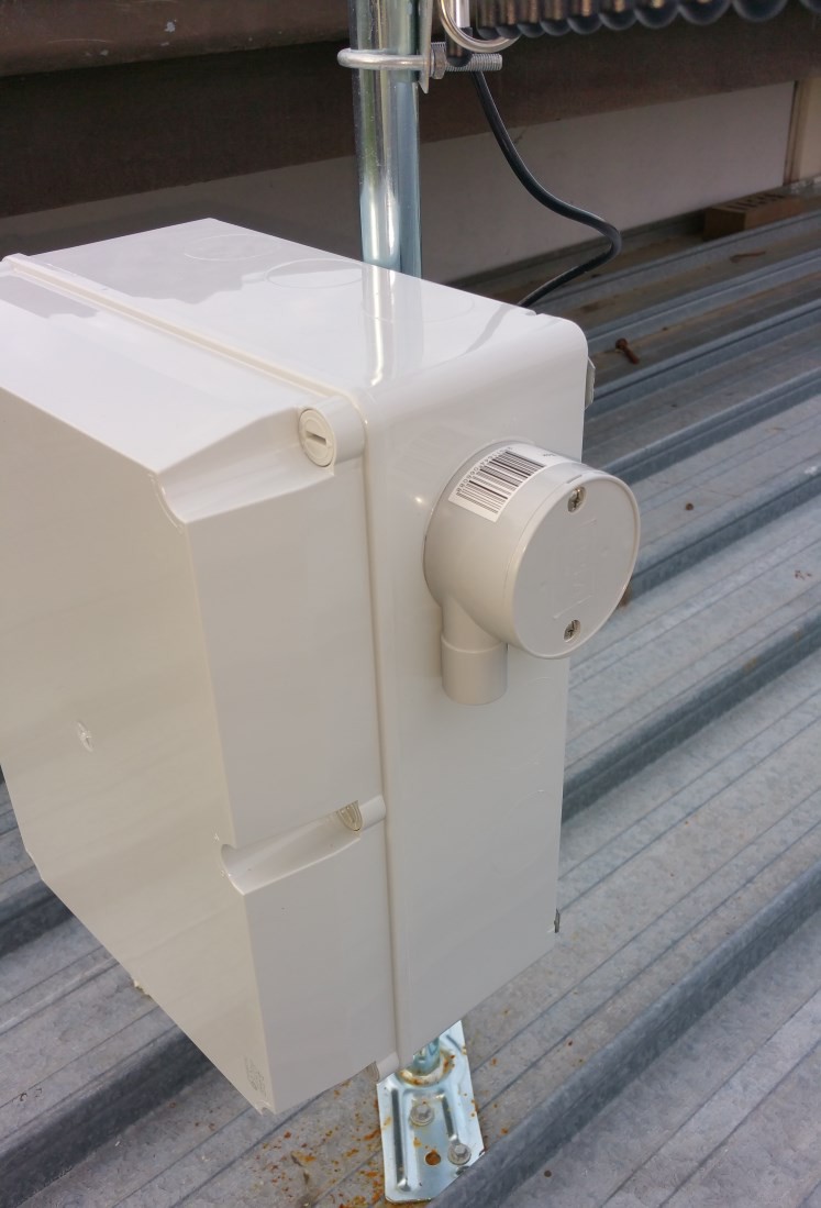
Since the enclosure is IP68 rated it's pointless putting the sensor in the enclosure so I needed to route it outside but also need to keep it out of direct sunlight and out of the water.
I done a trip to Bunnings and picked up a cheap Junction Box and some silicone sealant to use to glue the box to the side of the enclosure. Then I went to Jaycar for some wire, a pin header plug and an IP68 cable gland.
I assembled the cable connector and tinned the wiring on the ground before climbing on the roof of the shed to install the sensor. I took my Soldering Station onto the roof with me as thankfully I was able to disconnect the power from the Raspberry Pi 2, then unplugged the power-pack for the Hard drive and used the mains power socket to power the Soldering Station.
I drilled the hole for the cable gland in both the existing enclosure and the junction box but the thread on the cable gland was nowhere near long enough to use the gland to attach the two together. I prioritised the enclosure and used the rubber gasket to ensure it was water tight, then drilled the hole in the junction box oversize so it would fit over the top of the cable gland. I used the silicone sealant to glue the junction box to the side of the enclosure.
I soldered the GND, SDA and SCL lines to the second set of terminals on the TinyRTC module but had to run a wire upto the GPS module to tap the 3.3v VCC terminal there since the TinyRTC is a 5v board. Once that was complete, I plugged the BMP085 board into it's header and screwed the cover on the junction box, plugged the HDD back into power, reconnected the Raspberry Pi 2's power and put the cover back on the enclosure.
![]()
Once back inside I SSH'd into Einstein and ran a quick "sudo i2cdetect -y 1" and the sensor was present on the i2c bus which was a good sign given the sensor had been sitting in my shed for a year or so in a breadboard doing nothing but gather dust.
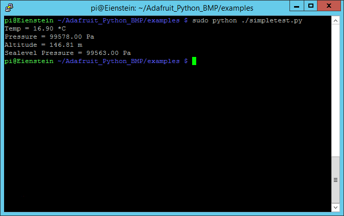
I installed the Adafruit Python library for the BMP085, ran the install script then fired up the simpletest.py example file and was greeted with some good looking data.
![]()
Now all that is left to do is to start working on a web framework to extract, log and display the ever increasing list of data being grabbed by Einstein. I do have some plans for future sensors but I need to work on some hardware before I can install them!
-
Einstein Science Upgrade
09/01/2015 at 03:50 • 0 commentsGiven the additional RAM and CPU capacity of the Raspberry Pi 2 in the Einstein box I have decided to do some "Upgrades" on the hardware in the box to try an do some science.
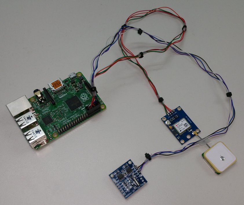
As part one of this is to install a Real Time Clock so the Pi 2 has an actual Hardware RTC, and a GPS for accurate location measurements and time keeping, etc. A quick trip to Ebay and I had a cheap TinyRTC module and a uBlox 6M GPS ordered which turned out to be fully functional and no issues which is good given you can occasionally get some bad modules from the cheap Chinese sellers.
The TinyRTC board was modified to remove D1, R2, R5 and to remove and wire bridge R6 so that I could replace the rechargable LIR2032 battery with a much easier to source CR2032 battery. The CR2032 batteries in this application last 10 years so it's no issue not having a rechargable battery.
I wired both the uBlox and the TinyRTC up to a harness which connects to the GPIO header on the Pi 2. I then grabbed my spare Pi 2 and done some testing on the bench. I did find I had the GND, TX and RX lines messed around on the uBlox module but a quick shuffle of the pins in the plug on the harness and that issue was resolved without breaking the module.
I configured Raspbian to use the TinyRTC as the HW clock and setup GPSD and verified everything was working fine and now all I need to do is get on my shed roof to install the harness into Einstein.
![]()
-
Bridge Installed
07/19/2015 at 23:41 • 0 commentsHaving completed the software installation (Part 2 of my configuration log is pending) I spent this afternoon installing the boxes in their final locations.
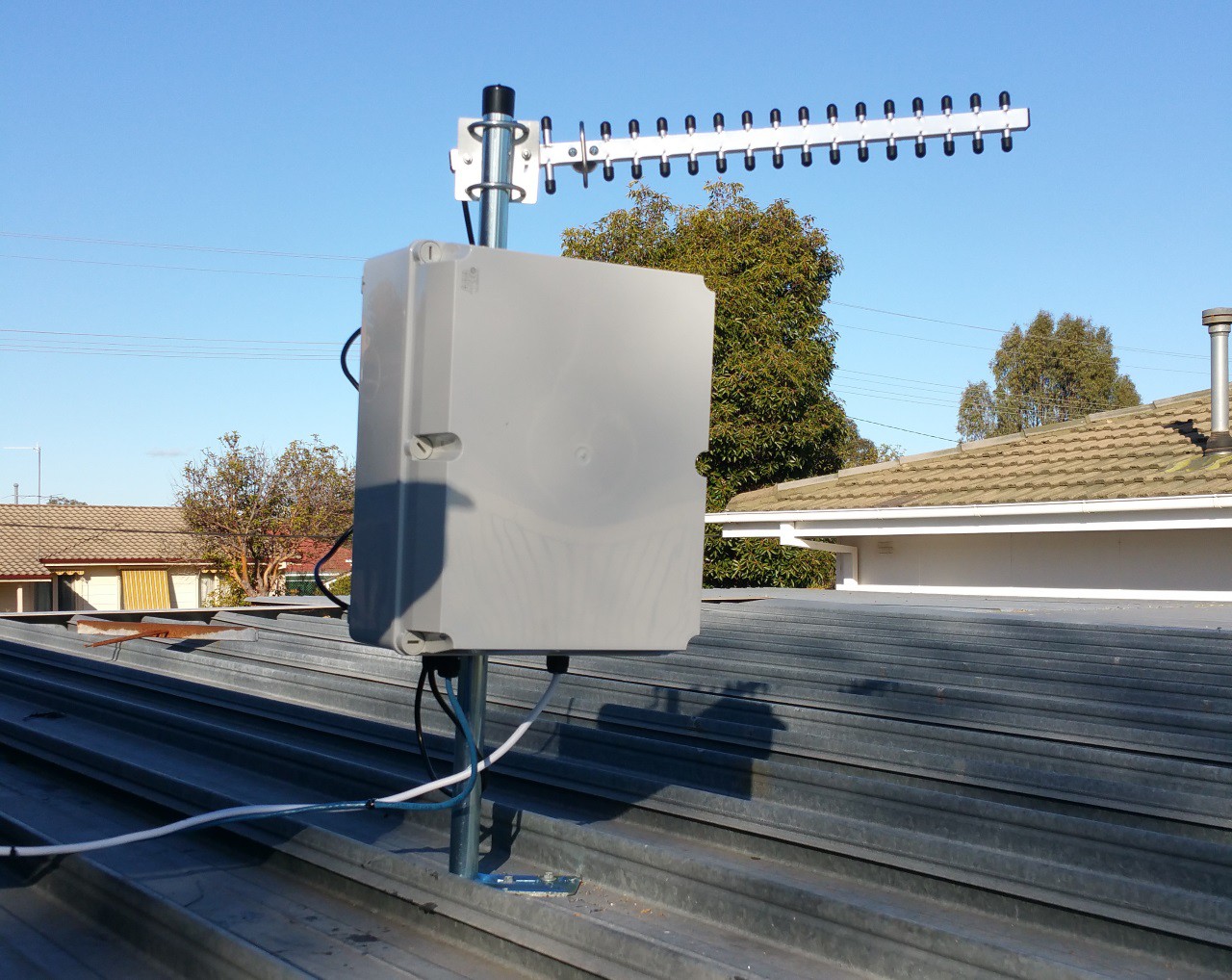
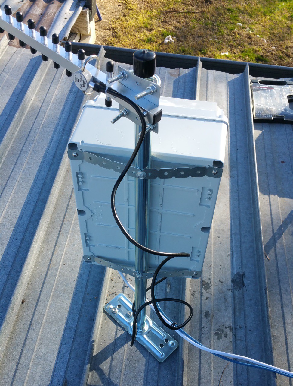
My box was installed on the roof of my garage as the existing TV antenna mast was too far away from my garage where my switch gear is located.
![]()
The antenna was aimed by eye at the TV antenna mast at my mother-in-law's house, the spread on the signal will easily take care of any misalignment. The only issue I faced was my next door neighbour's shed and a bottle brush tree in my mother-in-law's neighbour's yard
![]()
After installing the second box and aiming it back at my garage roof, I connected my phone to my mother-in-law's access point inside the house, opened a terminal and was able to ping across the bridge with no issues.
Trying to ping the internet was failing but a quick traceroute showed the packets were stopping at my cisco router. A quick tweak to the access lists allowing my mother-in-law's subnet and the issue was resolved.
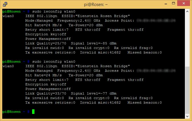
![]()
The link speed isn't the greatest but given the obstacles in the way it's probably not unexpected. The Link Quality varies and the Bit Rate tends to shift back and forwards between 18Mb/s and 24Mb/s. I would have liked a higher speed, but it is still enough to saturate my internet link.
I do need to do some tuning with OpenVPN to try and work on the speed of the encryption. I was only getting about 3.5MB/s to 4MB/s transfer speeds and it was maxing out the Pi 1's CPU. I will be doing some monitoring of the CPU temperature to see if a mild overclock is possible, it was a frosty morning this morning and the Pi 1 was running about 30°C where my Pi 2 was only 18.5°C (for reference, the standing water pools outside were frozen)
Finally I was able to install a Chromecast on my mother-in-law's TV and set her phone up with the Chromecast and Netflix apps, she was able to watch some legal TV goodness with no stuttering or quality issues so over-all I would call the exercise a success.
-
Raspbian Configuration - Part 1 (Base System)
07/13/2015 at 13:02 • 0 commentsHaving lost my original SD card image when the card failed, I needed to rebuild my Raspbian configuration. This is the outline of the process I used to rebuild the image and configure Raspbian and OpenVPN to act as the wireless bridge between the two houses. I started the process with a fresh NOOBS based install of Raspbian.
Step 1: Update Base Install
Firstly, I need to update the packages to the latest versions. I open a connection to my Pi 2 with Putty from my Windows box.
I execute the commands:
sudo apt-get update
sudo apt-get upgrade
![]()
The first command updates the package metadata so that apt knows what is available. The second command scans the system, prompts for permission then downloads and installs the updated packages.
Step 2: Configure eth0 and wlan0 network interfaces
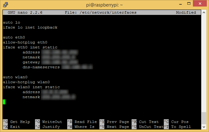
Next I need to configure the IP addresses used by the Pi 2. DHCP assigned addresses aren't suitable for a device intending to act as a network gateway, so I need to configure static IP addresses for both eth0 (Wired LAN) and wlan0 (WiFI).I execute the command:
sudo nano /etc/network/interfaces
Then I delete the existing contents and use the following config (My actual IP's have been masked)
auto lo iface lo inet loopback auto eth0 allow-hotplug eth0 iface eth0 inet static address xxx.xxx.xxx.xxx netmask xxx.xxx.xxx.xxx gateway xxx.xxx.xxx.xxx dns-nameservers xxx.xxx.xxx.xxx auto wlan0 allow-hotplug wlan0 iface wlan0 inet static address xxx.xxx.xxx.xxx netmask xxx.xxx.xxx.xxx![]()
Next, I need to disable the DHCP Client Daemon (dhcpcd) which I found assigns the network interfaces a DHCP address even though I have set a static IP above.
To do this I use the command:
sudo update-rc.d dhcpcd disable
Step 3: Set Hostname & GPU Memory Split
Now I just need to configure the Hostname and the amount of RAM assigned to the GPU in the Broadcom SoC before rebooting. Since the GPU will not be needed I will be assigning it 16MB of RAM which is the smallest amount possible. To perform this configuration I will use the 'raspi-config' utility.I use the command:
sudo raspi-config
First I set the Hostname. I access the 'Advanced Options' menu, choose 'Hostname' and enter 'Eienstein'.
![]()
Then I set the GPU Memory. Again I access the 'Advanced Options' menu, then I choose 'Memory Split' and enter '16'
![]()
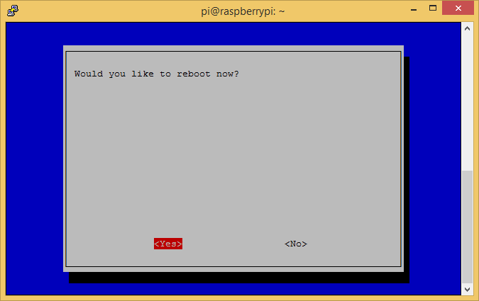
I then choose the 'Finish' option to complete the process. I am prompted to reboot and choose 'Yes' which reboots the Pi 2.
![]()
Step 4: Enable IP Forwarding
After waiting a couple of minutes and reconnecting to the Pi on it's new IP address, I am ready to enable IP Forwarding which allows the linux kernel to route packets between interfaces by using the routing table.I execute the command:
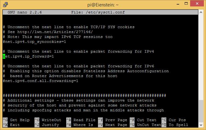
sudo nano /etc/sysctl.conf
I locate the line containing '#net.ipv4.ip_forward=1' and remove the hash to uncomment the line. This script is used by linux during the boot process to configure certain system parameters, in this case forwarding of IPv4 packets.
![]() Next I execute the command:
Next I execute the command:sudo sysctl -p /etc/sysctl.conf
This causes the system to reload the configuration file and apply the changed settings.
Step 5: Configure Wireless Access Point for wlan0 interface
Now I need to configure the wlan0 (WiFi) interface to act as a Wireless Access Point so the other box can connect to the wireless network without requiring a dedicated access point. I need to install the 'hostapd' daemon in order to act as the access point.I run the commands:
sudo apt-get install hostapd
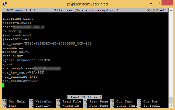
sudo nano /etc/hostapd/hostapd.conf
The first line uses apt to download and install the daemon, the second line created a new configuration file for the daemon. I use the following config (again masking identifying details)interface=wlan0 driver=nl80211 ssid=xxxxxxxx hw_mode=g #wme_enabled=1 #ieee80211n=1 #ht_capab=[HT40+][SHORT-GI-40][DSSS_CCK-40] channel=11 macaddr_acl=0 auth_algs=1 ignore_broadcast_ssid=0 wpa=2 wpa_passphrase=xxxxxxxx wpa_key_mgmt=WPA-PSK wpa_pairwise=TKIP rsn_pairwise=CCMP
This config sets up an 802.11g Wireless LAN on channel 11 which in my area is clear of any other wlans so I don't have collisions with other networks, I use WPA2 with a pre-shared key.
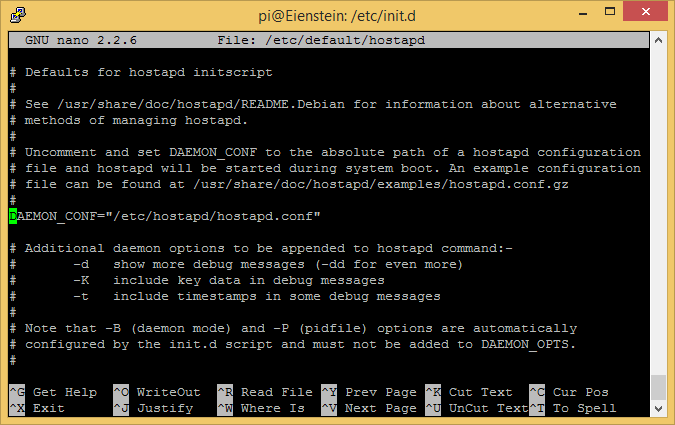
![]() Now that I have the configuration I need to tell the daemon where the config file is, in order to do this I need to edit the default script and modify the 'DAEMON_CONF' value.
Now that I have the configuration I need to tell the daemon where the config file is, in order to do this I need to edit the default script and modify the 'DAEMON_CONF' value.I use the command:
sudo nano /etc/default/hostapd
then locate the line 'DAEMON_CONF=""' and change it to 'DAEMON_CONF="/etc/hostapd/hostapd.conf"'
![]() All I have left now is to enable the hostapd daemon on boot and to start it, so I use the commands:
All I have left now is to enable the hostapd daemon on boot and to start it, so I use the commands:sudo update-rc.d hostapd enable sudo service hostapd start
At this point, I have a working base system with a static LAN IP address and a USB WiFi adapter acting as a Wireless Access Point. In the next update I will configure the OpenVPN server and the associated tun0 virtual network adapter, configure the iptables firewall on the wlan0 interface so that only ICMP pings and the OpenVPN UDP packets are accepted. I will also configure the routing table so that traffic to and from the remote network at my mother-in-laws is passed between my LAN and the VPN tunnel across the Wireless link.
-
Block Diagrams
07/09/2015 at 06:36 • 0 commentsI have added to the Gallery simple block diagrams of the enclosures on each end of the link.
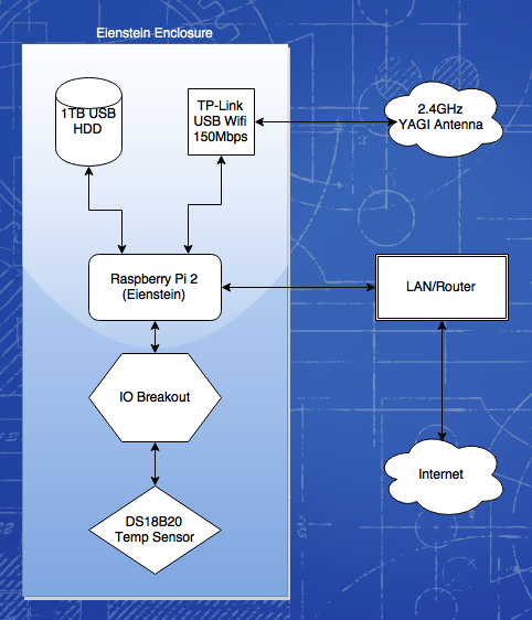
The Eienstein enclosure is on my end and is responsible for acting as the WiFi Access Point and serving up the OpenVPN connection across the WiFi link to Rosen.
![]()
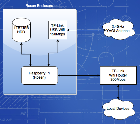
Rosen is the far end, acting as the Client, connecting to the Eienstein AP and the OpenVPN client. It is also responsible for assigning IP addresses, Gateways and DNS via DHCP to the remote lan.
![]()
Once I have the link working, I will add web caching to Rosen to try and reduce load across the WiFi link, and also (if possible) locally caching any media from a NFS or SAMBA share on my local LAN.
-
Two Pi 2's and from scratch software
07/08/2015 at 13:56 • 0 commentsSo, I should have taken the warm SD card as a sign, I got home and connected up my new Pi 2 only to be presented with the same symptoms as the previous board.
I put the SD card into a PC reader and got some strange results from Windows trying to read the card. I grab a spare Micro SD and throw a fresh copy of Noobs on it and sure enough the Pi boots. I swapped the card into the old Pi 2 and it leaps into life also. Score!!
So now I have two working Pi 2's, a cactus Sandisk 16Gb MicroSD and no working, tested OS left. On the bright side, I can now do project logs on the configuration of Raspian to act as the encrypted bridge.
-
Pi 2 Arrived (Eventually) & Electrician Organised
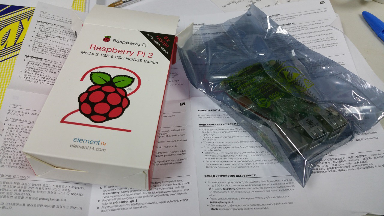
07/08/2015 at 06:04 • 0 comments![]() So, finally after almost a whole day of waiting and two trips to the Post Office, I have my new Pi 2. I got an email from Australia Post saying my package had been delivered. No one around the office had seen it. I dashed home during my lunch break to see if it had been delivered there (alas, it had not) and to meet up with my Electrician friend who is installing power & ethernet under the eaves to show him the Job.
So, finally after almost a whole day of waiting and two trips to the Post Office, I have my new Pi 2. I got an email from Australia Post saying my package had been delivered. No one around the office had seen it. I dashed home during my lunch break to see if it had been delivered there (alas, it had not) and to meet up with my Electrician friend who is installing power & ethernet under the eaves to show him the Job.I also have to have my mother-in-law's fuse box rewired with all new breakers and safety switches because of the age of the house but it's only going to cost me some time working on his office PC's and fixing his Arcade Machines.
I checked in with the Post Office near work where the office mail comes too and there was no sign of the package at all. I had a meeting to attend to so couldn't hang around. Not long before the Post Office closed, I done a quick trip back and they had managed to locate the parcel, it was put into my office's PO Box for delivery tomorrow.
-
Replacement Pi 2 Ordered
07/07/2015 at 03:09 • 0 commentsSo, AU$69 later and my replacement Pi 2 is on the way from Little Bird Electronics. Express post to my office so hopefully I will have it tomorrow.
I also have organised my electrician friend to come around to install outdoor Mains Power and Ethernet points under the eves near the TV antenna at my mother-in-law's house.
-
Assembly of Pi 2 WiFi Box
07/06/2015 at 11:12 • 0 commentsThe assembly of my Raspberry Pi 2 based WiFi box was very straight forward. The power USB cable on the Pi 2 was a bit snug against the veroboard for the GPIO header breakout but it went in no problem after trimming a notch out of the board.
Once it all went together and I plugged it in to power, the board lights lit up and the HDD spun up but there was a solid ACT light on the Pi 2. I extracted the Pi 2 and powered it up connected to my PC and still there was nothing, no HDMI signal and no ACT light.
The MicroSD card also started to get a little warm to the touch, not a good sign. I had the Pi 2 configured and working on the bench prior to assembly, looks like I have to order another one pronto from Little Bird Electronics!
Note to the Raspberry Pi Foundation: Hey Guys! How about a thin conformal coating to help protect the base PCB from accidental spikage!
Einstein-Rosen Bridge (WiFi)
An encrypted WiFi bridge from my house to my mother-in-laws house across the back court so she can watch Netflix
 robheffo



 So, finally after almost a whole day of waiting and two trips to the Post Office, I have my new Pi 2. I got an email from Australia Post saying my package had been delivered. No one around the office had seen it. I dashed home during my lunch break to see if it had been delivered there (alas, it had not) and to meet up with my Electrician friend who is installing power & ethernet under the eaves to show him the Job.