-
First ESP8266 versions have arrived
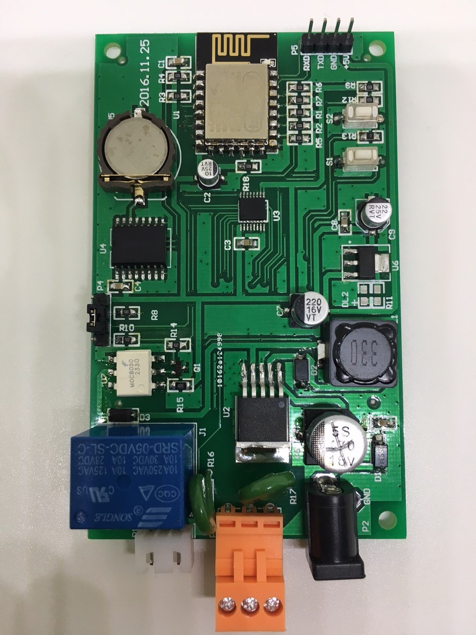
01/05/2017 at 04:37 • 0 commentsAfter many months I finally have the first order of ESP8266 based Tick Tock Timers.
There was actually 2 revisions of the ESP8266 version due to a few pin behavior issues.
All GPIOs on the ESP8266 are being used by the Tick Tock Timer so choosing the function of each pin became a problem when some anomalies were discovered with certain pins.
Issue 1: Relay Closing/Opening at boot.
GPIO 0 was being used to trigger the relay as this was supposed to be a very basic function, however when the ESP8266 first boots this pin goes low for a moment, causing the relay to sometimes close/open when powering on. This had to be switched to a more boot stable pin. Pin 0 become LCD CS it is not effected by this boot low behavior and the relay became pin 10.
Issues 2: LCD Backlight pulsing when dimmed
GPIO 15 was being used to generate PWM to control screen brightness however when the PWM value is set < 400 the I noticed the screen brightness would pulse every second. An oscilloscope confirmed that the pin was unsuitable for stable PWM generation. Backlight was moved to 16 at it proved stable for PWM and Touch CS
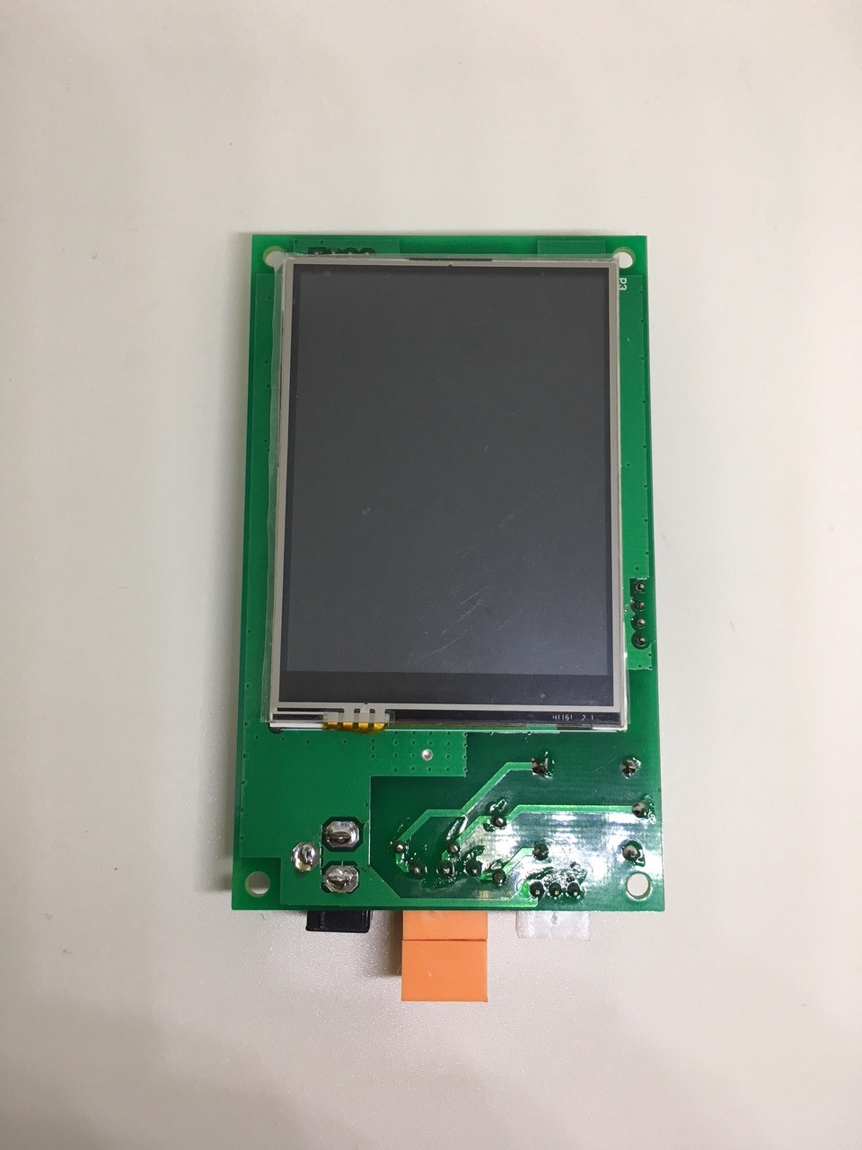
was moved to 15.Here are some pictures of the new hardware.
Summery of changes
- ESP8266 (Originally MEGA2560)
- SPI ili9341 (Originally ili9325 8Bit)
- Operating Voltage 6-24v (Originally 6-9v)
- Opto-coupled relay protection added
![]()
![]()
- ESP8266 (Originally MEGA2560)
-
First Tick Tock Timer installed in Australian School
12/22/2016 at 15:49 • 0 commentsTo date, all Tick Tock Timers have been exclusively installed in CAN/USA Schools & Factories, as well as a few other random US institutions (including a US Army Barracks).
Being located in Australia I have not seen any of this installations and have never received any feedback from customers due to selling straight to a distributor in Canada.
That all changed this week when a work colleague of mine discoverer one of the Tick Tock Timers on my desk at work which I had been running for testing purposed during the day. ( Yes I have a day job )
it just so happened his wife is the principle of a locale primary school who were currently looking for a more modern school bell timer since there current one couldn't handle different bell times on different days as well being very basic and easy to completely reset by accident.
Within a few minutes of discussion a Tick Tock Timer had been sold to Shelley Primary School WA and I found myself in the shoes of a school bell timer installation technician! (as opposed to developer)
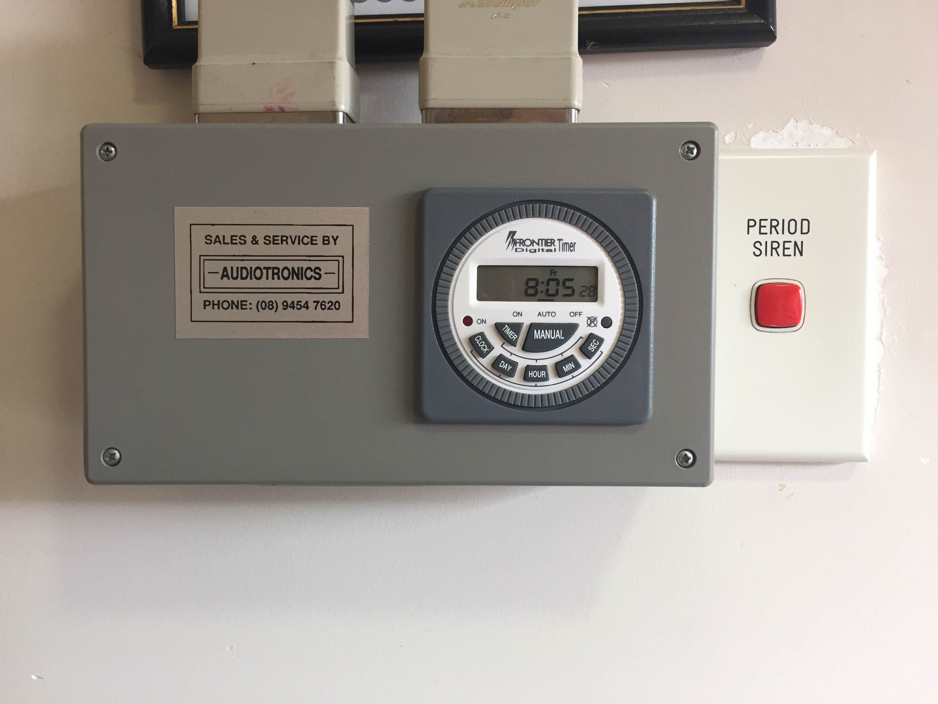
This is what I was up against. It had been running for over 10 years with decent time accuracy...quite impressive really...but quite out dated and limited.
![]()
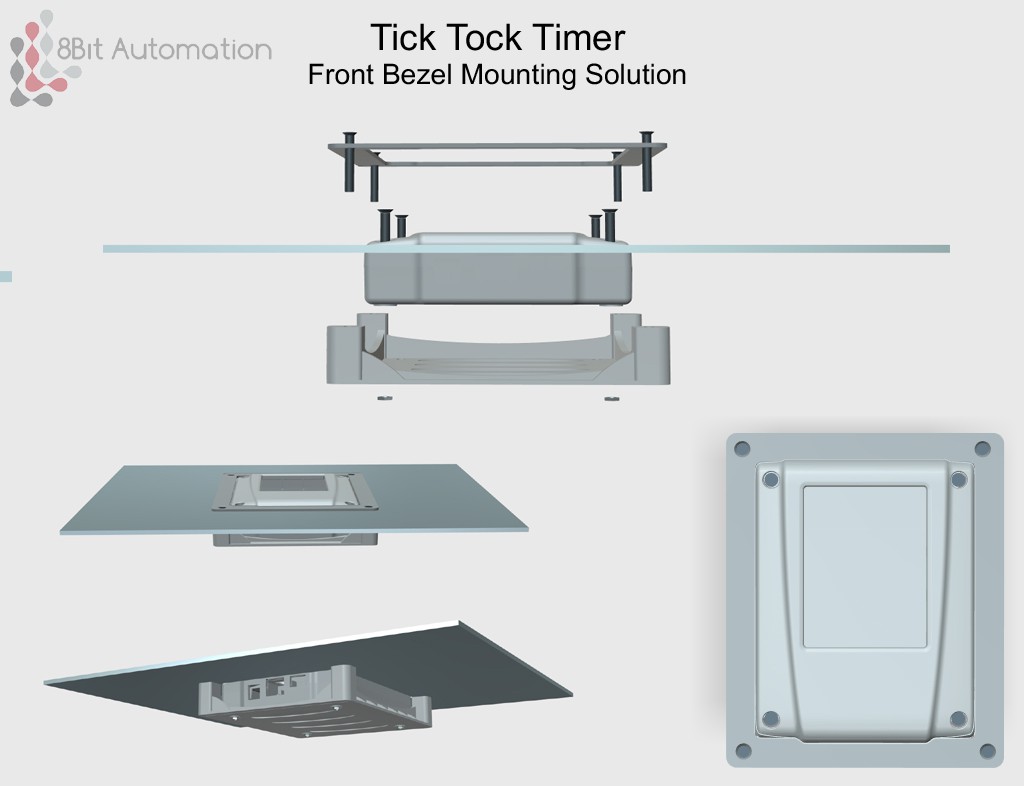
After inspecting the old timer installation I realize that the Tick Tock Timer needed a flush mounting bezel of sorts. I had over looked this.
I spent the weekend designing and 3D printing a flush mounting solution.
![]()
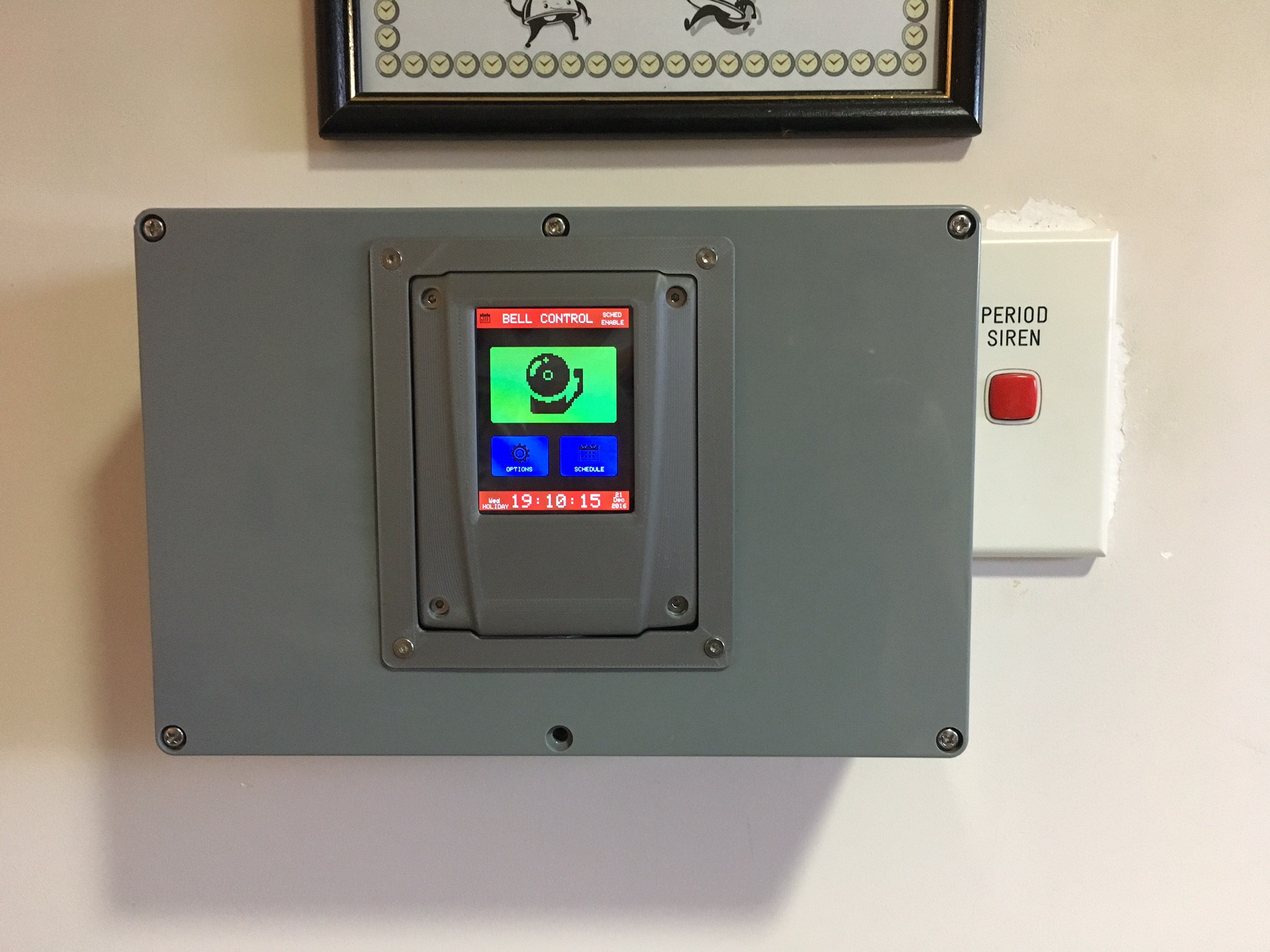
Now that I had a mounting solution sorted it was time to install the Tick Tock Timer.
After removing the Frontier Timer timer, installing a large box, tinkering with the crazy wiring mess behind it for over an hour or 2 I had the Tick Tock Timer installed.
![]() After showing the principle I had already pre programmed the bell schedule including the early Wednesday finish, set a 4 digit PIN code on the menu to lock it out, added in school period holidays and set the manual school bell manual ring time to 5 seconds she was absolutely blown away by the product.
After showing the principle I had already pre programmed the bell schedule including the early Wednesday finish, set a 4 digit PIN code on the menu to lock it out, added in school period holidays and set the manual school bell manual ring time to 5 seconds she was absolutely blown away by the product.When I mentioned I had 3D printed all of the plastic housing including the mounting bezel she pulled a blank stair and said "oh that nice..." ...Not sure she knew what I mean by that.
-
OTA Firmware Updates now added
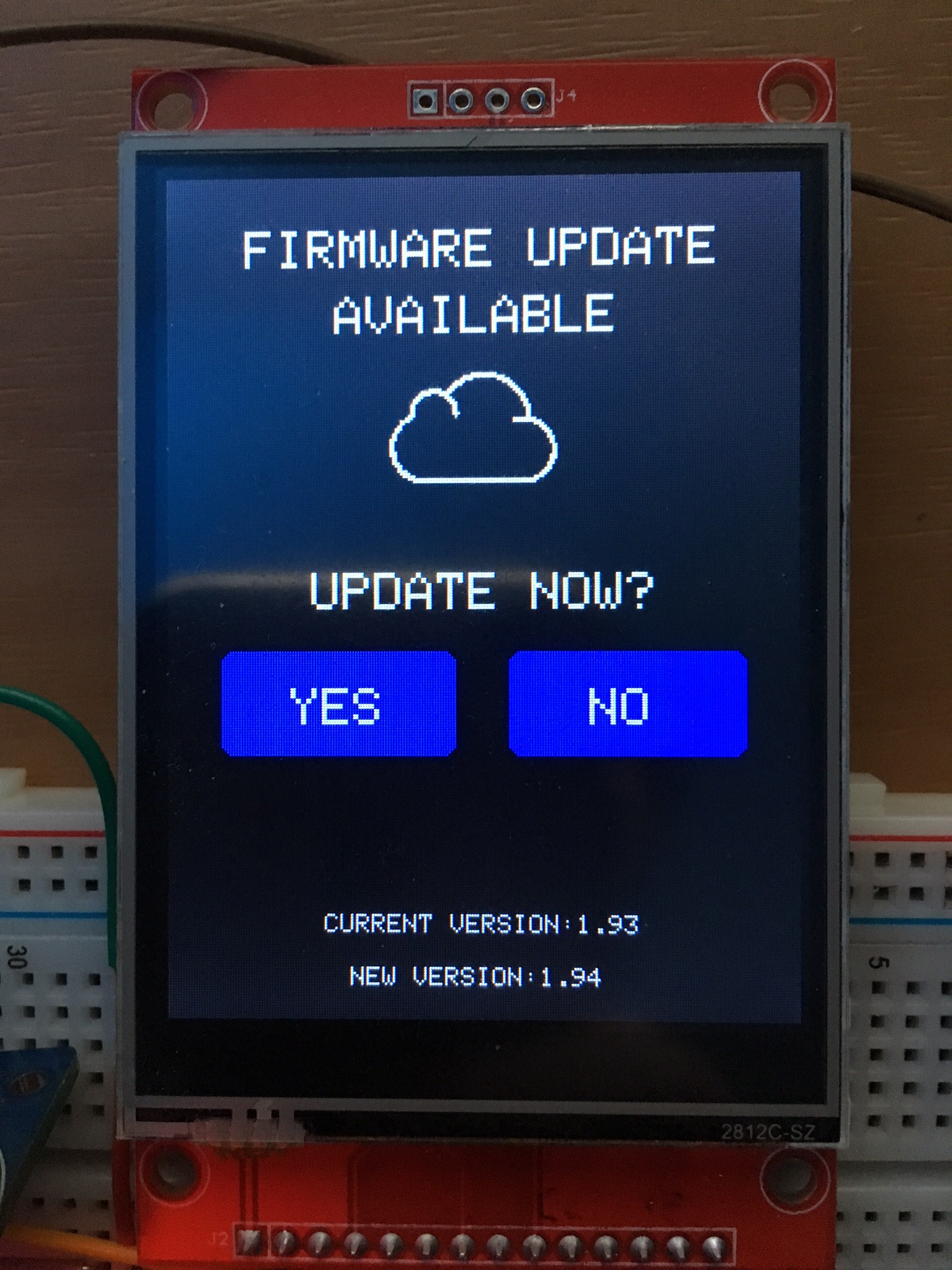
12/22/2016 at 15:22 • 0 commentsI have now added OTA (Over The Air) firmware updating to the Tick Tock Timer.
This is how it works
- Used selects Firmware Updates from the About menu
- Timer reads a .txt file hosted on my NAS drive hosted on a HTTPS share (ISP Static IP)
- The .txt file has the most recent firmware version number
- If it is a different firmware to whats currently installed then the updated .bin is downloaded and installed on the timer from the same HTTPS share
The system uses the Arduino ESP8266 Core OTA update libraries, with example code ported, adapted and changed to suite my requirements
Wifi connectivity is handled by the VERY nice open source Wificonfig library which allows you to create an open AP from the esp8266, connect to it, scan for wifi networks and then input the wifi password for the network you wish to connect to all using you smart phone browser.
NTP is also available IF you have connected the timer to the internet.
![]()
-
Decentralised Manufacturing: 3D Printed Cases
11/07/2016 at 04:25 • 0 commentsSo the question I have been asking myself for a few months now is "should I switch to injection molding for the case?"
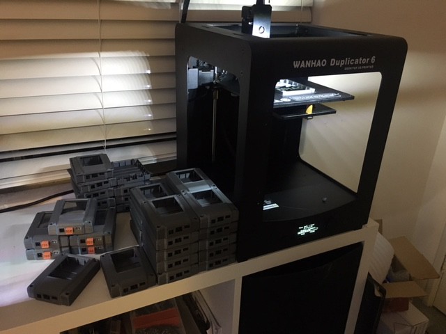
I'm still 3D printing all of the Tick Tock Timer case and I am able to produce around 30 good quality prints per month using 2x 3D printers and the cost per case is currently around $3.50 AUD each.
I could probably switch to injection moulding within the next few months however a part of me wants see how far I can push Decentralised Manufacturing, so for the time being I will continue 3D printing cases.
On a side note my Polysmooth 3D print finishing system should arrive by the end of he year (kickstarter campaign from early this year) which should add a whole new level of shine and smoothness to the surface of the enclosures!
![]()
-
Switch to ESP8266 & Product Manual!
11/07/2016 at 01:09 • 0 commentsIts been a while since my last update so here are all the things iv been working on.
- The Tick Tock Timer is now based on the ESP8266 MCU and ili9341 SPI. The original version was Atmega2560 and ili9325 8Bit. This was mainly due to the reliability and shortage of ili9341 screens as they have become discontinued. The switch to SPI was due to the ESP8266 being more suited to it. ALL usable pins on the ESP8266 12E are being used, I was lucky there was enough! The new board is undergoing a second revision as a few issues crept in due to the pin choices and strange behaviors of certain pins, mainly GPIO0 at boot time.
- The new version has PWM back light control which is great and now can be run from 7v > 18v instead of 6v > 9v
- First australian school will be installing the new timer next month. I will personally be installing and setting it up for them. All other installation are in USA/Canada (so far around 40 of them)
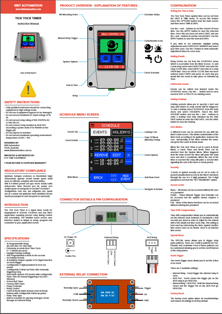
- I have almost completed the Manual! (thanks Mark T. for your amazing design work here) It folds up to the same size as the timer almost.
![]()
-
Tick Tock Timer ported to ESP8266 and ili9241!
08/25/2016 at 11:57 • 0 commentsIts been a while since my last posting to this is whats news
- There are around 25 tick tock timers "in the wild" running various school/factory bell systems
- Issues with quality control on ili9325 screens (white flashing)
- Product manual in the works
I have been having quality issues with ili9325 screens, with around 15% of produced boards having screen which flash white when touch is being read from the screen.
Due to this I have long terms goals to switch over to the more common ili9341 screens
This screen will also allow PWM screen dimming which is something I (regrettably) didn't pursue the current ili9325 production version.
After failing to get it working the ili9341 to work with my Mega2560 I realized the screen isnt 5v logic tolerant (despite what the ebay listing claimed....)
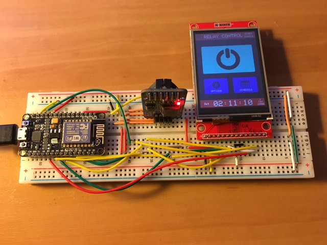
Since I didnt have the components to to a logic conversion I decided to attempt a port of the firmware over to the ESP8266 NodeMCU
After breaking most of the timing features by updating the RTC library, switching to an ili9341 library and XPT2046 touch library, a few glasses a wine and about 5 hours I have breadboard ported the TICK TOCK TIMER to the ESP8266 / ili9341!
Still work to do
- Port all clock code firmware over to updated library
- Add EEPROM.commits to all EEPROM write (currently not saving on power off!)
- Add NTP (Why not?)
- Add NTP settings such as time zone
![]()
-
KICKSTARTER FAIL!
06/08/2016 at 05:34 • 0 commentsSo I didnt get enough backers for the product to get kickstarted. Doesn't surprise me really, quite a niche product and I didn't put any effort into social media advertising. Not really my think.
Not to worry, I have 2 small companies in the business of selling timer solutions who are very interested in selling and marketing the Tick Tock Timer.
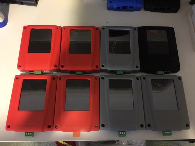
I have 10 units on route to Canada and 2 sent off locally here in Australia. Fingers crossed Ill be able to move 20 - 40 of these a month. When I get to that level I move away from 3D printing the case and switch to injection molding
Here is a batch of 8 I prepared.
![]()
-
Kick Starter Attempt!
02/03/2016 at 09:51 • 0 commentsSo iv gone ahead and posted a kickstarter project to try and get the funding I need for an Injection Molded Case!
https://www.kickstarter.com/projects/2105597804/tick-tock-timer
I dont like my chances of success but iv got nothing to loose in trying!
-
Overview Video Posted
01/13/2016 at 13:24 • 0 commentsThe Tick Tock Timer projects still moving along!
Iv made a quick video overview of the timer
Iv decided to try and raise some funds to get an injection molds made for the enclosure.
Ill post the kickstarter link if it get approved. I dont expect anyone to back it, but iv got nothing to loose trying right? I seen worse things get funded...."a late night pizza run?"
-
Finally have a GOOD 3D printed enclosure
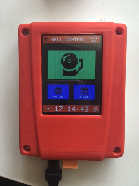
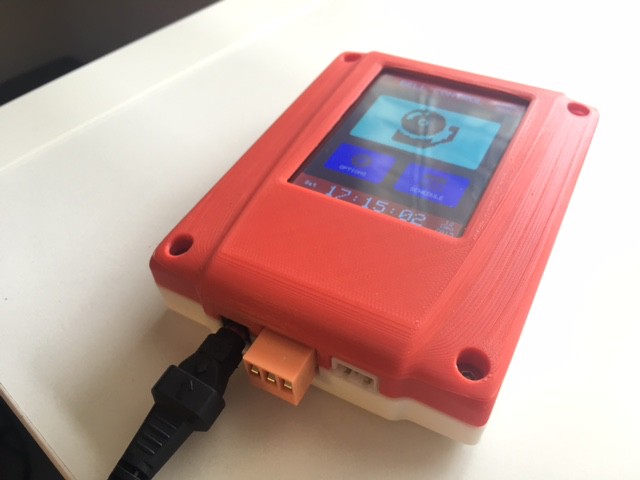
12/12/2015 at 12:52 • 0 commentsAfter much experimentation I have produced a great 3D print of my products enclosure completed with production PCB installed.
I sliced the enclosure into 3 parts to make sure no external surfaces shows the horrid scars of 3D printed supports.
Im very pleased with my result!
The injection mold will be made from this design.
![]()
![]()
Tick Tock Timer
The Tick Tock Timer is a School Bell timer packed with features
 After showing the principle I had already pre programmed the bell schedule including the early Wednesday finish, set a 4 digit PIN code on the menu to lock it out, added in school period holidays and set the manual school bell manual ring time to 5 seconds she was absolutely blown away by the product.