It's been a little while since my last update. Haven't accomplished a whole lot since then, but I have updated the schematic to what will hopefully be a final "base" version. Anything added on will be in a later revision. So, this is what's changed:
- Fixed mistakes from previous post
- The big change here is swapping out full wave rectification with half wave. I chose a schottky diode because the lower voltage drop affords the use of a smaller smoothing capacitor, without any ill side effects from the small reverse leakage current.
- Moved RF connections around to default SPI pins on PIC. There was really no reason to keep it as is and this saves me from having to remap pins in software.
- Connected IRQ RF pin. Not sure if I'll use this but it's there now.
- I was going to add a fuse, but it turns out the wall wart transformer has one built in. Bonus!
- Added test points. This is something I always mean to do but forget about. Really useful for troubleshooting.
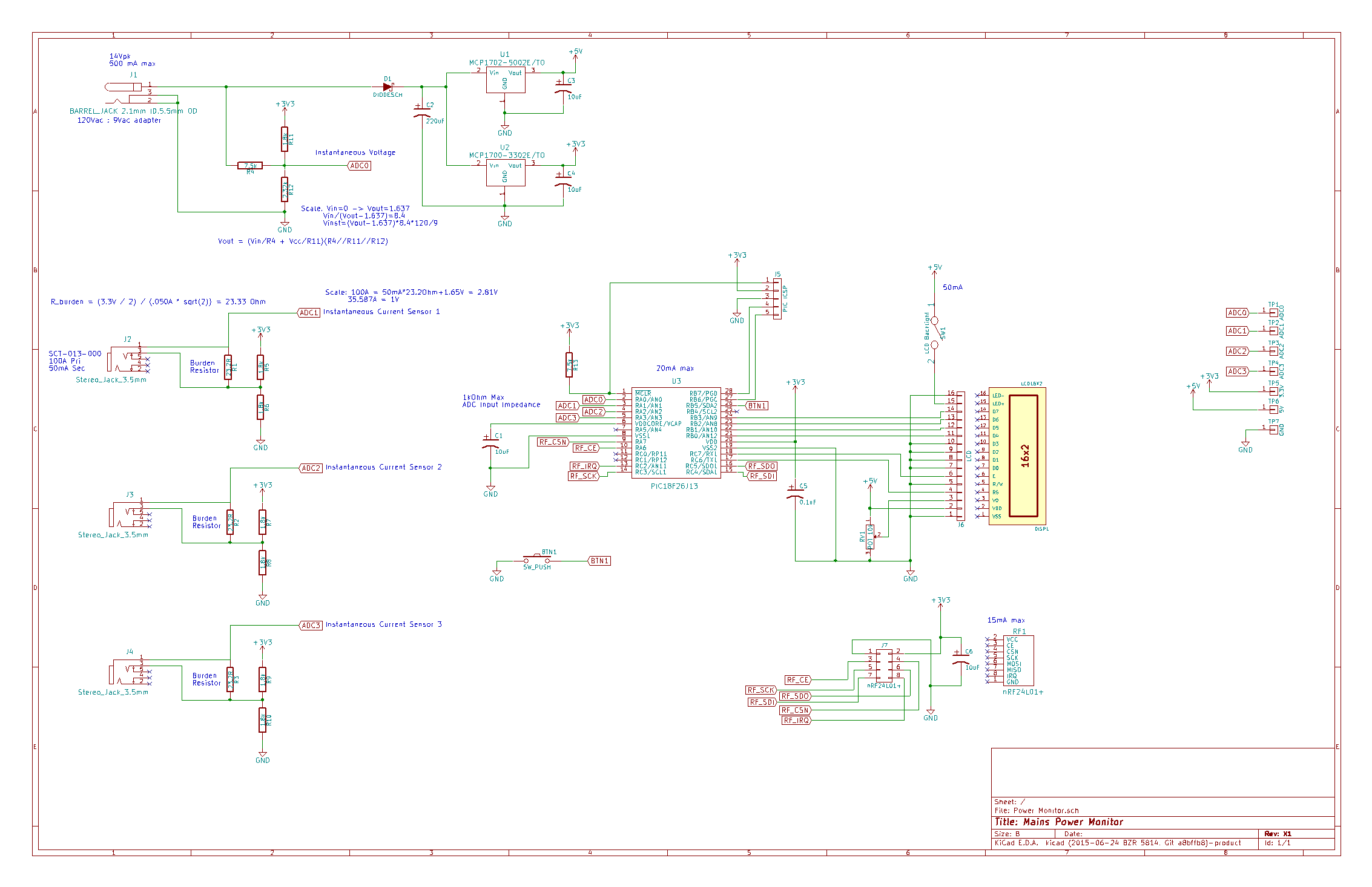
I thought about throwing an LED in there for some diagnostics, but I have an LCD so I can just update that with pertinent error info. I'll go ahead and order this board in a couple days, and it should get here in a couple weeks.
You'll also notice some ADC scaling information on the schematic. This is because I've already started on that part of the code and I'll probably post an explanation for my methodology in the next few days.
Discussions
Become a Hackaday.io Member
Create an account to leave a comment. Already have an account? Log In.