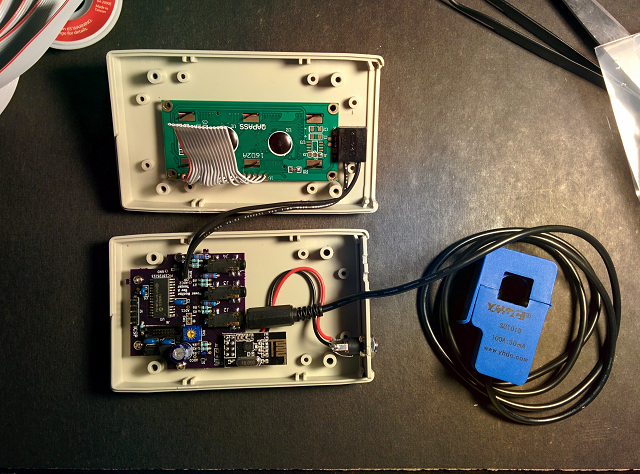
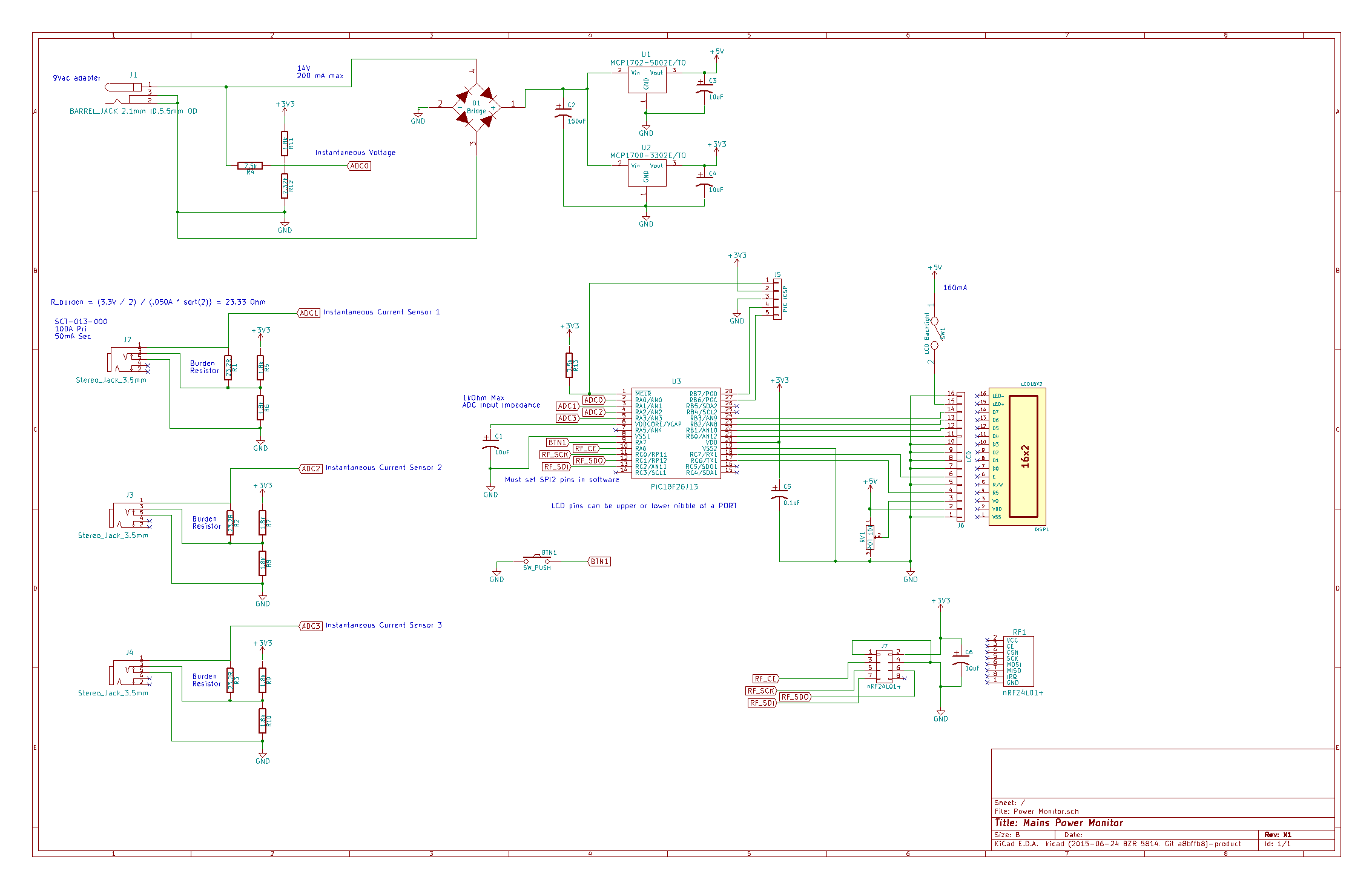
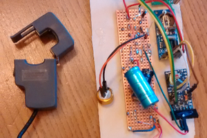
It works by gathering voltage and current data to calculate power. Voltage is measured from an AC/AC adapter wall plug (which also supplies power to the unit). Current is measured from 3 split core current transformers. Two for each phase of incoming power to my apartment, and another to put on a wire connected to any of the circuit breakers in the panel to measure individual loads (like Heating/Cooling, Washing Machine, Bedroom, etc.).
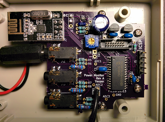
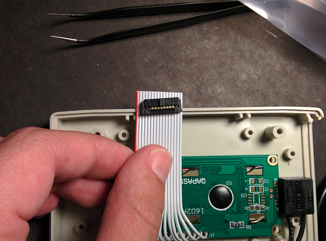
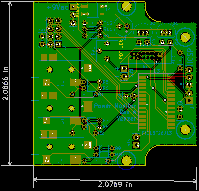
The brains of the unit will be a PIC18F26J13. I like PIC's because I'm familiar with them, and this one has a 12-bit ADC which is handy for those voltage/current measurements. It also has plenty of I/O to interface with extras. Extras like an LCD! Which is where power info will be displayed locally. However, in order to have a web server with pretty graphs I'll need to send the data elsewhere. One of the cheapest ways to do that is with one of those nRF24L01+ modules that you can get for about a $1 each.
Raspberry Pi's seem to be pretty good as stand alone web servers, so I'll try that. As a bonus it has some exposed I/O pins that will allow me to use another nRF24L01+. From there I just need to store the data in a base(!) (probably SQLite), and serve up some chart plotting javascript, or some such.

 Nathaniel VerLee
 robert.c.baruch
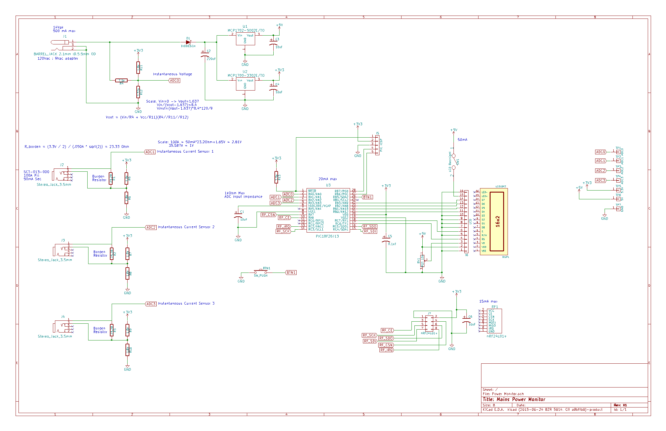
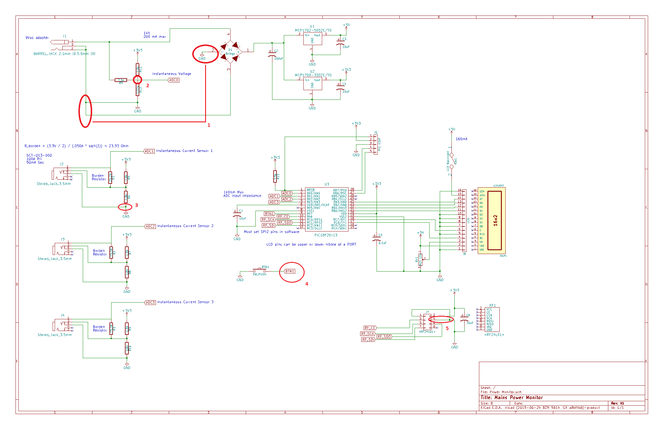
The ground at the bottom of R12 also grounds pin 3 of the diode bridge D1. This puts the 9Vac input across D1 pins 2 and 4, so it is essentially shorting the transformer during 1/2 of the cycle.
Should there be a connection where the wire from R4 crosses over the wire between R11 and R12? With this connection and the above ground connected to the transformer, you'll get a sine wave at ADC0, but the output of the bridge is a half-wave, and the 9Vac transformer and the bridge rectifier are going to get very hot and eventually fail.
If you remove the ground from one side of the incoming 9Vac, I don't see how this will give you a sine wave centered on Vcc/2 as neither side of the transformer is ground referenced from the output side of a full wave bridge rectifier. For that, you really need to either use a half-wave rectifier, a single diode, so that one side of the transformer is connected to ground, or a center-tapped transformer and 2 diodes for a full-wave bridge.