 qquuiinn
-
PCBs Arrived!
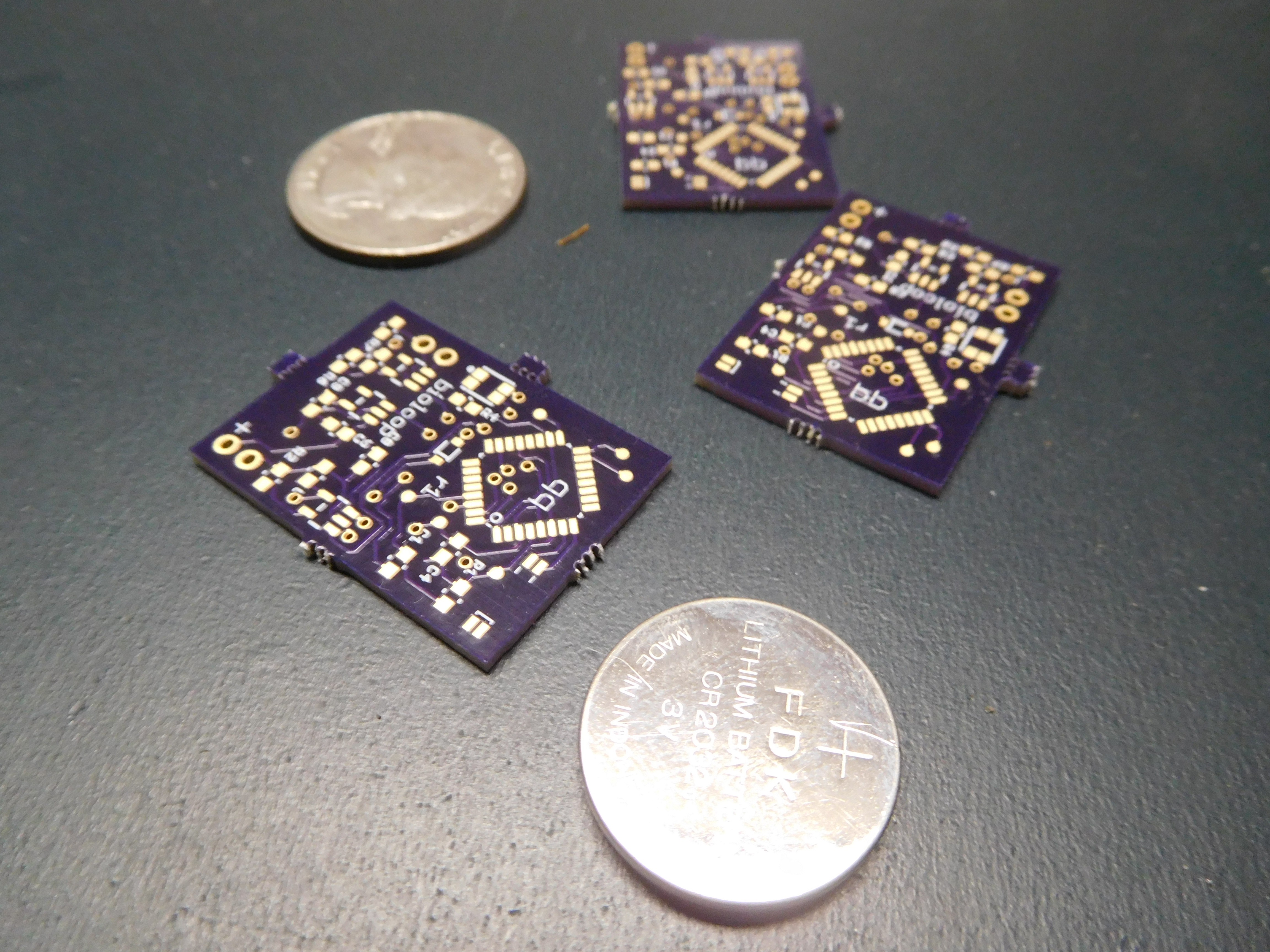
07/29/2016 at 23:11 • 1 commentMy OSHpark order came in today a day early. It's the first PCB that i've completed (second if you count some free freelance work I did on reddit awhile ago) and I was very impressed. The flashy mailer, contained three! bioloop boards. They all felt very well made, but were WAY smaller than I was expecting. The picture below shows all three along with a 20mm coin cell battery and US quarter for scale. Hopefully this means I can make bioloop very compact and unobtrusive.
![]()
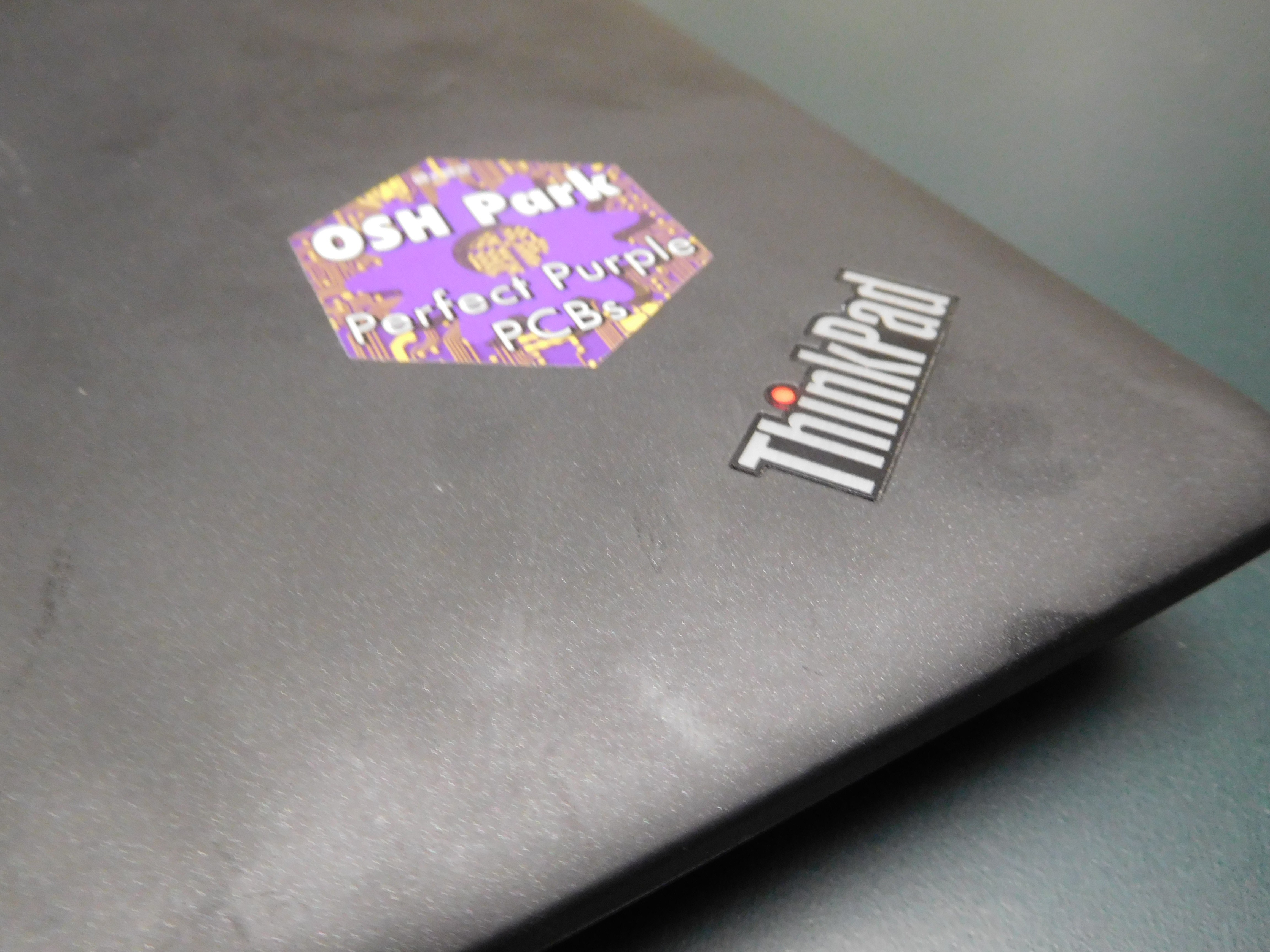
I also got a very quality-feeling vinyl sticker, which I promptly stuck on my laptop.
![]()
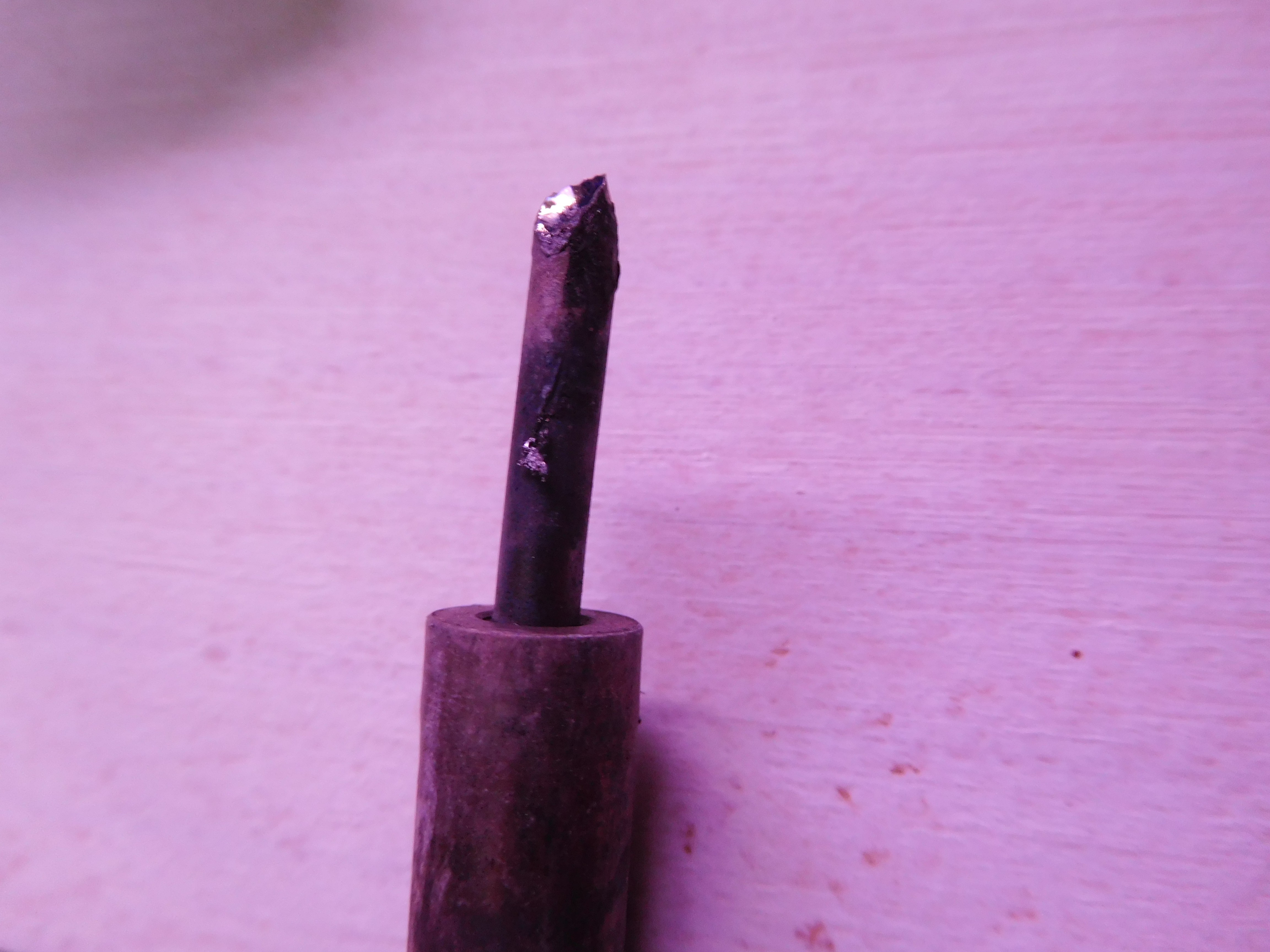
At this point, I have all the stuff to get bioloop's electronics working. But before then, I'll need to get ahold of a decent soldering iron. All of the passives are 0603, and while I have a set of dentist's picks to help maneuver the tiny lil' components around, my iron is showing it's age. I bought it in 2011 at a chain hardware store and haven't replaced the tip since.
![]()
Love you, OSHpark <3
-
New pictures, updated project files
07/25/2016 at 22:19 • 0 commentsI just finished updating the project log with new pictures of the bioloop prototype. The white perfboard in the pictures contains the older, more sensitive GSR sensing circuit, which means developing new GSR projects is as easy as connecting the power and signal wires to any microcontroller.
I also updated the github with all the new project files. The parts for the "final" wearable bioloop arrived today. I'll start sharing more of it's design once the boards arrive.
-
Current Progress
07/15/2016 at 23:48 • 0 commentsBioloop, since 2014, has existed in three different forms
- Mid 2014, designed to use IR LEDS to track heart rate. Connected with an attiny85 and vibration motor, it would alert users during heart rate spikes caused by anxiety attacks. Very similar to #The Temperizer . Never got out the front gate.
- Early 2015, this was the version I entered in the Hackaday Prize. GSR electrodes connected to wrist, feedback through a LED matrix. No storage. Initial design was to have all feedback be instant. Had some really good prototypes but no fruit.
- Late 2015/Early 2016, the current version. Essentially a minimalist, version of v2 with datalogging. I have the schematics and BOM lined up with finalized software and hope to make this one my 'finished prototype'
I have everything in order to start ordering parts for my final version, which should be done hopefully buy the fall of 2016 if everything goes fast and according to plan. Stay tuned, as I will be updating the github folder with relevant project files.
-
Update to project log coming soon
07/15/2016 at 03:38 • 0 commentsThanks to all the people who are following bioloop! Sadly, I have been neglecting to update the project log, but I have been (slowly) making progress, and the prototype I have now is much better than what it used to be. Stay tuned for big changes to bioloop!
-
Skin Contact Quality
08/19/2015 at 07:40 • 0 commentsRecently, I have been putting new the sensor amplifier circuit through the paces. Most of the time it works great, and I am not willing to go back and change it, or else all of my development time would be wasted. I need to move forward fast to meet deadlines.
Before running tests, I usually have to open a raw data serial feed to make sure that the skin contacts are in a prime location, and that the sensor values have stopped moving around. That is a complex, wasteful solution. I won't have access to a serial port for debugging in the final version, and neither will the end user. Overall it makes a pretty bad product. Good connection with the skin is the number one thing that needs to happen in order for bioloop to be useful, and it is probably where most of the user error will stem from.
To solve this problem, I made a sketch that checks for proper contact and waits until the sensor values stop jumping around. It has a nice series of animations which display on the "X" display to guide the user through the process, running completely on the bioloop hardware. For now, it is a good test tool, and will eventually be integrated into the main version of the firmware. Using bioloop just got a little easier!
-
Ready for the Quarterfinals!
08/17/2015 at 10:02 • 0 commentsSo, I filmed a quick video at the last moment, showcasing where the prototype is at right now.
I'm sorry that I filmed in vertical video, I didn't realize it until halfway through the upload. In preparation for quarterfinals I also uploaded some (also blurry) diagrams showing how bioloop would be used and the basic design. Hopefully I can figure out how to use photoshop to draw those or at the very least scan them in...
-
Software work...
08/17/2015 at 09:31 • 0 commentsI don't understand computer science very well, but I have developed a rudimentary "algorithm" (if you can call it that) to interpret the information from the sensor. It scans for maximum/minimum readings, uses the value in the middle to establish a baseline, and gives the output value as a distance from this baseline. So far, things appear to be a little strange. Data seems to move up and down with no reason given, and I have not been able to get it to respond to induced stress very well. This is kind of a big deal, and I need to get the algorithm to work before adding all of the extras to make the firmware complete, which involves moving to the attiny sometime soon. Other code that I have used looks at the trendline of the data instead, perhaps that would be more useful? Some sources suggest looking for "SCRs", but my sensor is not nearly good enough to do that. Perhaps I need to see the variation in data, as one website I looked at saw a "cleaner graph" as a sign of reduced stress, and a noisier dataset a sign of more stress. Anyway, I need to get something working ASAP so I can meet the prize deadlines. The main concurn is just making sure bioloop will work well for everyone.
-
Final Amplifier Design
08/09/2015 at 08:19 • 0 commentsThe amplifier for bioloop required quite a bit of trial and error. I thought I had got it working, and the next day it didn't. After days of testing and many spilled resistors I decided on a final design, based off of a very helpful PDF that I linked. The original 'Cornell' sensor is connected to a differential amplifier with a gain of 1, along with a similar voltage divider/follower circuit as shown below.
![]() The dividers will be connected directly to a microcontroller pin, which will allow then to be shut on and off, saving power. Otherwise, small amounts of power would trickle through the voltage dividers, draining the battery.
The dividers will be connected directly to a microcontroller pin, which will allow then to be shut on and off, saving power. Otherwise, small amounts of power would trickle through the voltage dividers, draining the battery. The schematic is from my final PCB design for the bioloop, which has a dedicated analog sensing board to avoid noise from other electronics. It also allows the final design to be very small-only about 1inch by 1inch. I will post more pictures of the schematics when I get things squared away and working properly with the attiny84. Otherwise, hit up the github.
-
Amplifier Design and Laser Cutting
07/19/2015 at 22:41 • 0 commentsI attended the hackaday collaboratorium to fix some of the amplifier issues. A few community members offered help, but the most useful advice was a link to the eevblog video tutorials about opamps. I watched all of the videos and was then able to add another stage to my amplifier circuit, giving it more gain but not at the cost of bandwidth. I should be able to move to software now thanks to the great community on hackaday.io. Additionally, I will be redesigning the final case because I won $100 worth of Ponoko credit. I will be taking advantage of the variety of materials offered to make a leather watchstrap, bamboo faceplate, and scratchproof acrylic window. The bulk of the watch will still be 3d printed, however. For now, I will brush up on my Inkscape skills and continue to work towards the August 17 deadline to try and make a finsihed prototype.
bioloop
a biofeedback wristband with galvanic skin response: giving insight into emotions
 The dividers will be connected directly to a microcontroller pin, which will allow then to be shut on and off, saving power. Otherwise, small amounts of power would trickle through the voltage dividers, draining the battery.