 Nahuel
-
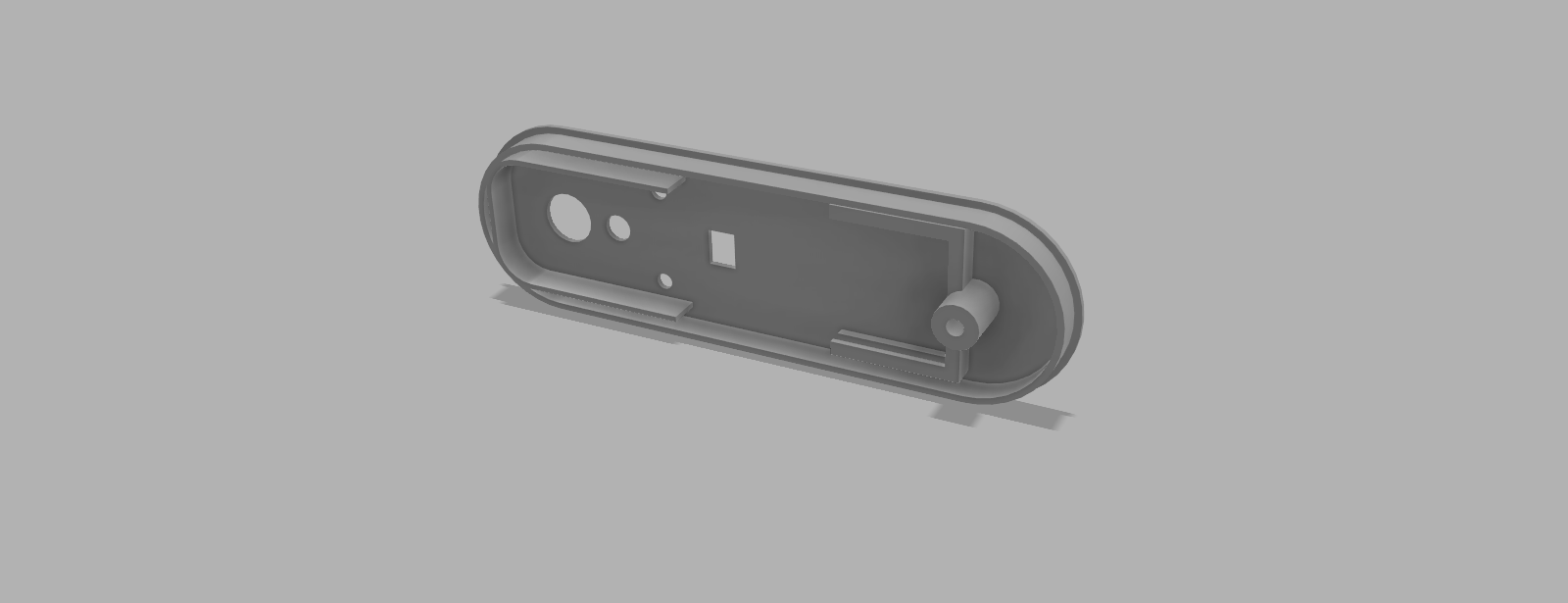
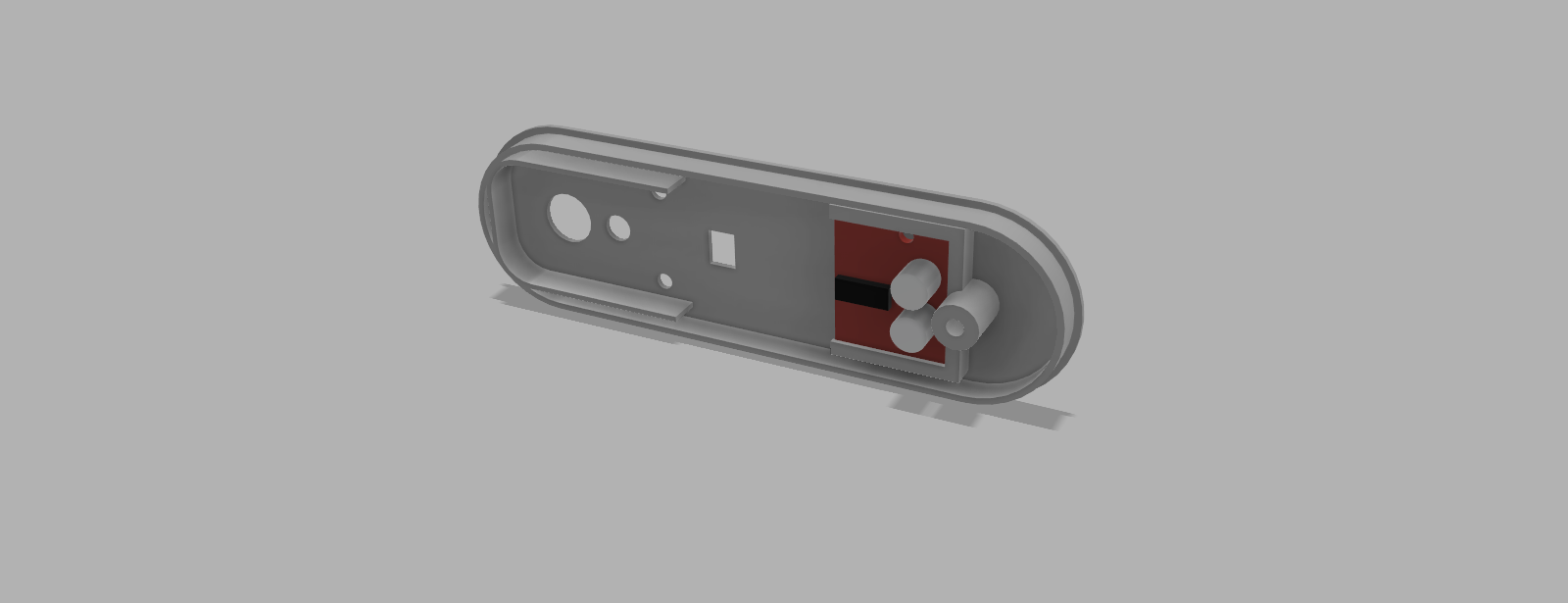
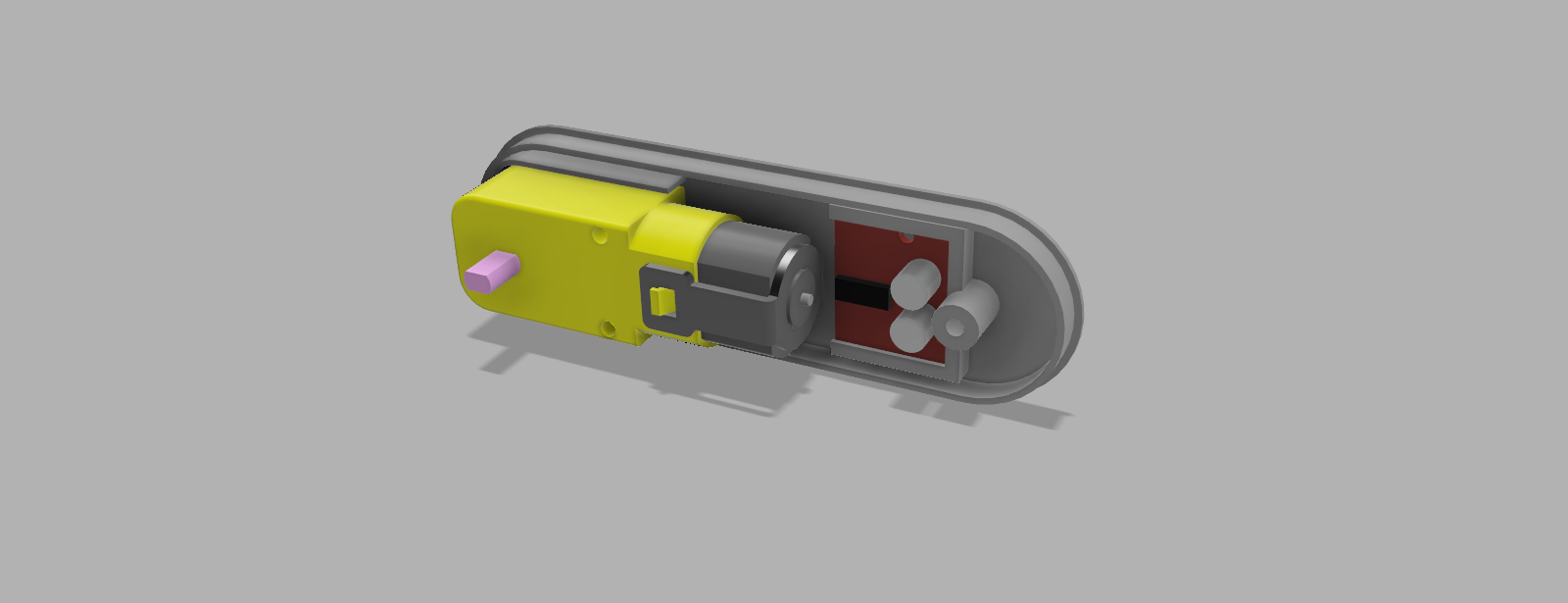
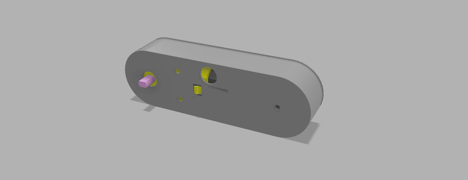
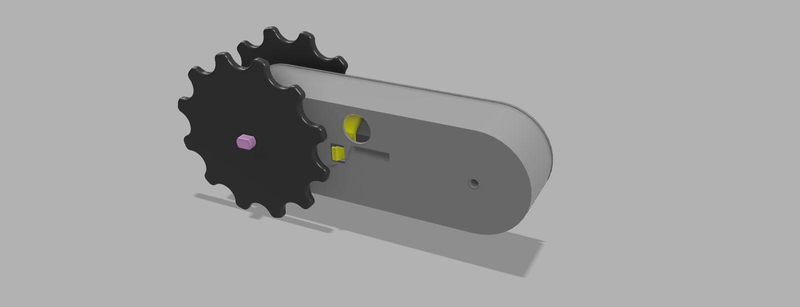
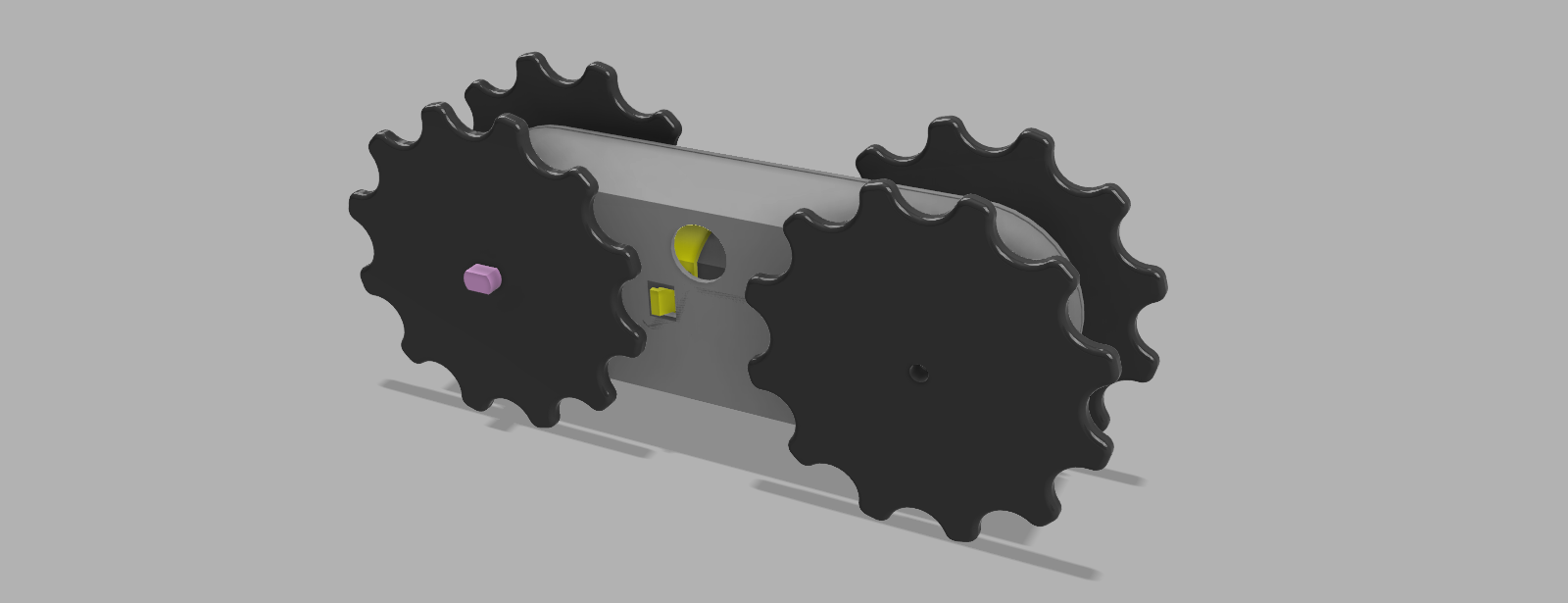
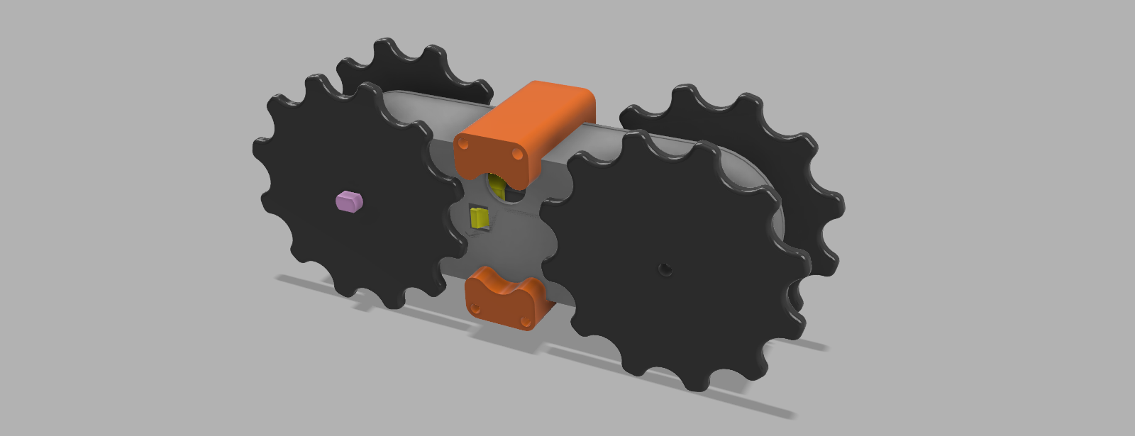
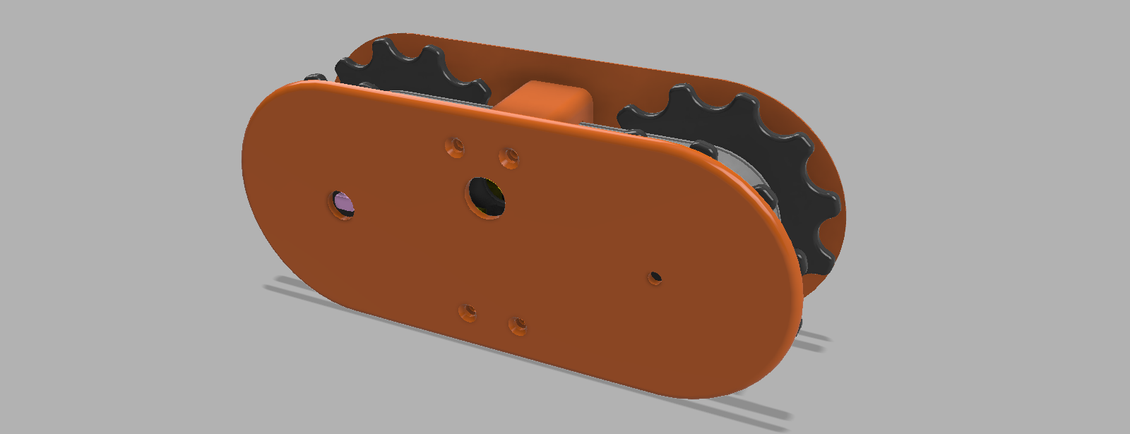
1Assembly sequence
In this sequence you can get an idea of the internals of this assembly:
![]()
![]()
![]()
![]()
![]()
![]()
![]()
![]()
-
2Recommendations
- When printing the driver wheels, I would recommend to place the motor axis into the wheels hole while it is still hot. The objective is to make it fit tight without needing further work.
- As this fits as a left or right track for a robot, there is no real left or right for this mount. That is why I named each side with A and B. Keep this naming to understand on which side of the assembly each par goes. If it has an A in the name, then it goes on the same side as the rest of the A parts, same for B.
- Check at the list of images uploaded to this thing to get an idea of where does each part should fit
- To link the tracks use a peace of 1.75 filament. If you leave about half millimeter extra on each side, you can melt that extra with a soldering iron, so you get a nice finish.
Self-contained Rover Tracks
This is a self-contained 3D printable rover track that can be reused on your projects.
Discussions
Become a Hackaday.io Member
Create an account to leave a comment. Already have an account? Log In.