Why?
An IoT weather station was our first product (http://kck.st/10DS44h), and what allowed us to start our company ACROBOTIC. As you can imagine, talking about DIY weather stations is a recurring topic of conversation in our day-to-day. And so, after our recent development efforts using the WeMos family of development boards for the ESP8266 (cf. ESPop and ESPicker), building a simple internet-connected device for displaying weather data was a must!
What?
The main goal is to have a dedicated, inexpensive, device that would help us avoid repeatedly checking websites, apps, email, writing scripts, etc., in order to monitor the current weather conditions for a location of our choice.

In terms of what's required, we challenged ourselves to use the minimum number of parts, and require no special tools/skills such as soldering.
Where?
As we're not the only tinkerers out there interested in a little desktop companion that displays weather data, we're documenting the parts list and build instructions on this project page for anyone to use. To make it even easier for those wanting to give the project a try, we'll have a kit available on our site (ACROBOTIC Industries) when we're done with the design.

As with all our projects, the software is free and Open Source!
How?
The hardware
To build a personal weather station we simply needed two pieces of hardware: an internet-capable microcontroller to gather the data, and a screen to display it, we tried to find the best solution considering ease of use and cost.
OLED display
Given our main goal of having a device with a small form factor that could sit on our desks, the first choice was to use a 0.96" OLED screen to display the weather data.
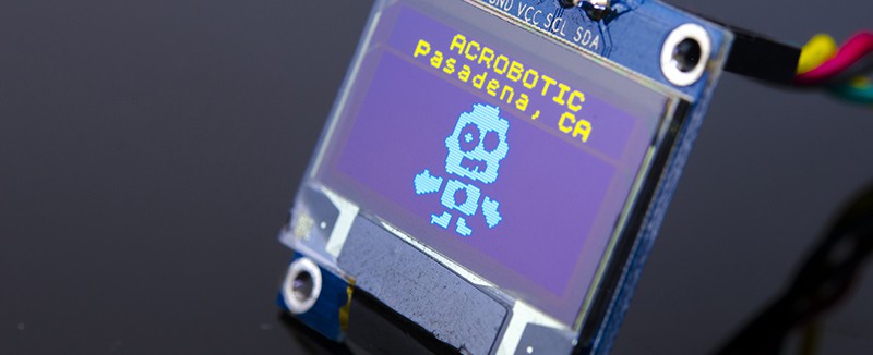
Not only are these displays small (and bright!), but they're very easy to control over i2c merely having to connect 4 wires to our microcontroller or single-board computer: 2 for power and ground, and 2 for the data and clock lines.
ESP8266 microcontroller (SoC)
What can we say about the ESP8266 that hasn't been said about the wheel, sliced bread, or the iPhone... we love it! It's the most convenient, inexpensive way to have a microcontroller running code while connected to a Wi-Fi network.
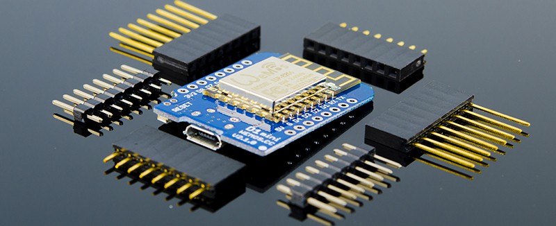
The SoC comes in a variety of modules, breakouts, and development boards. For this project, we evaluated a few options and settled WeMos D1 Mini for its compactness and availability of an OLED Shield that we could connect without the need of doing any wiring.
The software
Running on the microcontroller, we need software that's able to query weather data from dedicated servers, as well as to control the OLED screen to display the queried data.
Weather data API
As of this writing, the best site that provides a free API to query the current weather data around the world is:
Although accessing the API is free, we do need an API Key, and we're only allowed to send a certain number of requests for data per day. Luckily, weather conditions change on a relatively slow timescale.
Firmware
To perform the two tasks mentioned above, namely, query/parse data and control the OLED screen, we use a piece of code running on the ESP8266.
The firmware performs 4 major tasks:
1. Connecting to the Internet
Using the built-in Arduino library for the ESP8266 and entering our WiFi network credentials (ssid/password) we connect to the internet.
2. Querying the data
Using the built-in Arduino library for the ESP8266 , we create a WebClient object that allows us to send a GET request to the servers' APIs and retrieve the weather data.
3. Parsing the data
Using Benoît Blanchon's fantastic Arduino JSON library (available in the Library Manager), we can easily get the parts of the JSON-formatted data that interest us.
4. Displaying the data
Using a couple of OLED Arduino libraries, it's straight forward to display the weather data on the screen as well as our custom graphics. Most of the work, however, goes into making the UI both intuitive and aesthetically pleasing.
Once the project is completed, the final resting place of the firmware shall be:
- https://github.com/acrobotic/Ai_ESPecter (coming soon!)
Thanks for stopping by!
First prototype
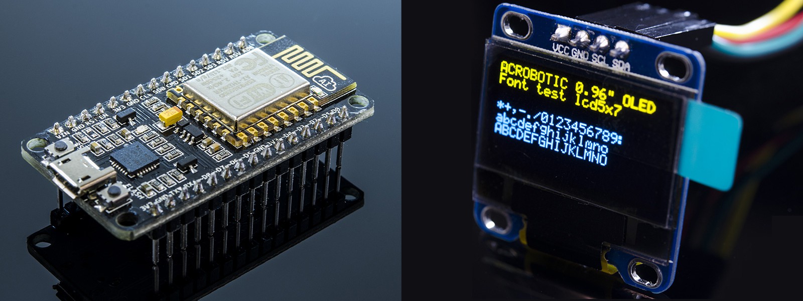
We started building the proof-of-concept prototype for the ESPecter using our preferred parts for the job. The main reason is that we had code snippets from previous projects and tutorials that we could re-use. Namely, the venerable DevKit ESP8266 development board and a standard SSD1306-powered, 0.96", 128×64 OLED screen.
Wiring
Wiring the two is straight-forward, keeping in mind that we need 2 4.7KΩ resistors to pull up the I2C lines. The I2C pins on the DevKit board are GPIO4 for SDA (labeled D2) and GPIO5 for SCL (labeled D1), this we wire them to the corresponding pins on the OLED screen PCB as shown in the diagram below:

Using the default I2C pins for the ESP8266 allows us to simply use the built-in Wire library for I2C communication. With everything wired up, it's time to test some code.
Fetching weather data
The very first thing we do is forget about the OLED screen and simply figure out how to get the data that we'll eventually display on it. We use the Serial Monitor for printing out the data, and worry about the OLED later.
To get the data we need to register with the Weather Underground service. The registration is what allow us to query the service and fetch the weather data. In the video below we explain, step-by-step, how to do this:
Once we've obtained the API key, we can proceed to write a barebones version of the code. Here's a breakdown of how the aforementioned tasks are accomplished in the firmware:
1. Connecting to the internet
Using the built-in ESP8266WiFi.h library, we use the begin method of the WiFi object with a couple of character arrays as arguments, which contain the credential to the network.
const char* ssid = "YOUR_SSID";
const char* password = "YOUR_PASSWORD";

WiFi.begin(ssid, password);

while (WiFi.status() != WL_CONNECTED)
{
  delay(500);   Serial.print(".");
}
As is typical, we do this inside the setup() function. Also, we use a while() loop to monitor the state of the connection. The loop runs until the connection is successful, though this blindly assumes that the network is available–a way to make the code more robust would be to handle cases where the connection isn't successful.
2. Using a web client
Using the built-in ESP8266WiFi.h library, we create an instance of the WiFiClient class, set up the request we're going to send to the Weather Underground server, and declare the buffer where we'll store the server's response.
We also construct the request we're going to send to the server, specifying a minimum set of header fields that are needed.
#define WU_API_KEY "YOUR_API_KEY"
#define WU_LOCATION "YOUR_LOCATION"
#define WU_URL "api.wunderground.com"

WiFiClient client;
static char respBuffer[4096];

const char request[] =
  "GET /api/" WU_API_KEY "/conditions/q/" WU_LOCATION ".json HTTP/1.1\r\n"
  "User-Agent: ESP8266/0.1\r\n"
  "Accept: */*\r\n"
  "Host: " WU_URL "\r\n"
  "Connection: close\r\n"
  "\r\n";
Next, we attempt to connect to the host site using the connect() method of the WiFiClient object. We do some basic error handling if the connection isn't successful, but once again we assume it will be successful.
Using the print() method of the WiFiClient object (not to be confused with its counterpart from the Serial class), we send the request. We then close and flush the connection, and we also wait an arbitrary-but-reasonable amount of time (1 second) for the server to respond.
Once the server responds, we use a while() loop to load the response into our character buffer. To do this, we use the read() method of the WiFiClient object.
client.print(request);
client.flush();
delay(1000);

uint16_t index = 0;
while(client.connected())
{
  if(client.available())
  {
    respBuffer[index++] = client.read();
    delay(1);
  }
}
By the design of the API to which we send the request, we know that the response from the server will be formatted in JSON.
Parsing JSON-formatted data
Although we know that the data is formatted in JSON, is we print out the character buffer we notice that there's some extra characters in the server's response. For this reason we use the strchr() method to trim the buffer (creating a new one) all the way to the first opening curly brace '{' where we know, by inspection, that the JSON-formatted data begins.
char * json = strchr(respBuffer,'{');

DynamicJsonBuffer jBuffer;
JsonObject& root = jBuffer.parseObject(json);
JsonObject& current = root["current_observation"];
String temp_c = current["temp_c"];
String weather = current["weather"];
data = "Temp(C): "+temp_c;
Serial.println(data);
Using the fantastic ArduinoJson library we can now parse the data. We can do so by creating either a Static or Dynamic JsonBuffer object (we chose the later), and calling its respective parseData() method. The JsonBuffer object(s) then allow us to pick the data we want by using the familiar keyed array notation.
For now, we can visualize the data in the Serial Monitor using the print() method of the Serial object (remember to initialize it in the setup() function!). But, the next step is to send it over to the OLED screen.
Displaying the data
Although several libraries exist (including our own!) for working with OLED screens, we chose to follow our quick-n-dirty standalone OLED demo:
As such, we created a helper file util.h containing a few constants including the font data. Please note that the file should be located in the same folder as the .ino sketch.
Then, it was a matter of creating a few low-level helper functions for setting up the OLED screen, and communicating with it. And one high-level function to print the data we wanted:
setTextXY(0,0);     // Set cursor 0th page (row), 0th column
displayString("DATA:");

void printData(String data)
{
  setTextXY(2,0);
  char __data[sizeof(data)];
  data.toCharArray(__data, sizeof(__data));
  displayString(__data);
}
We also encapsulated the data capture and parsing inside a getData() function, and the data displaying on the OLED screen inside the prinData() function. These two functions are called from within the standard loop() function every 10 seconds.
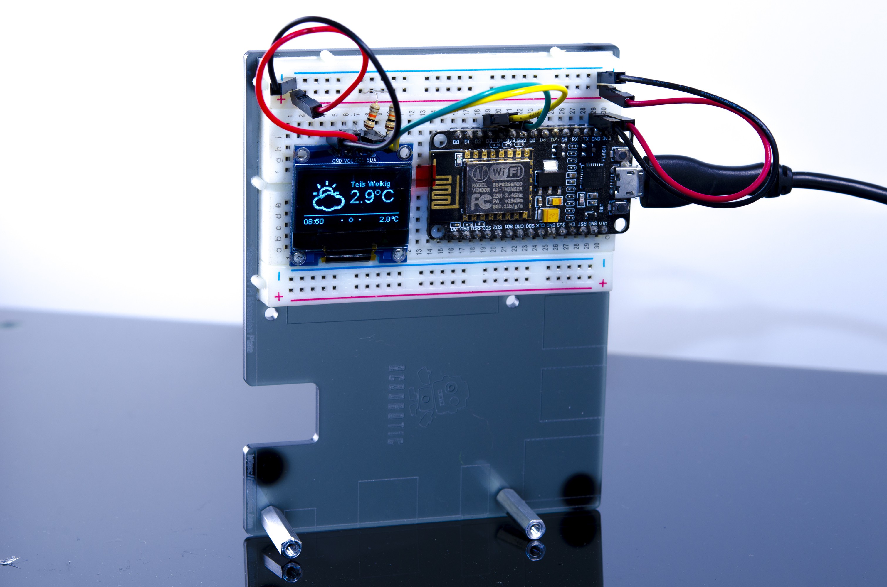
The prototype's firmware files are available at:
The ESPecter
With a solid functional prototype in hand we now move on to making it nicer, and turning it into something that anyone can use, wether they want to program it themselves or not. To do this we focus on the following improvements:
- Increased portability
- Migration to WeMos D1 Mini [done]
- Additional firmware features
- Configurable through a Web Interface [in progress]
- Weather-based alerts [in progress]
- Display weather for additional locations [in progress]
- Show historical weather data [in progress]
- Additional hardware features
- 3d-printed enclosure [done]
- Battery-powered operation [in progress]
Increased portability
As mentioned earlier, our goal is to have a small-sized, set-and-forget, physical device to display weather data continuously. To such end, and despite the joys of breadboarding, we choose to use the compact WeMos D1 Mini together with a compatible OLED Shield.
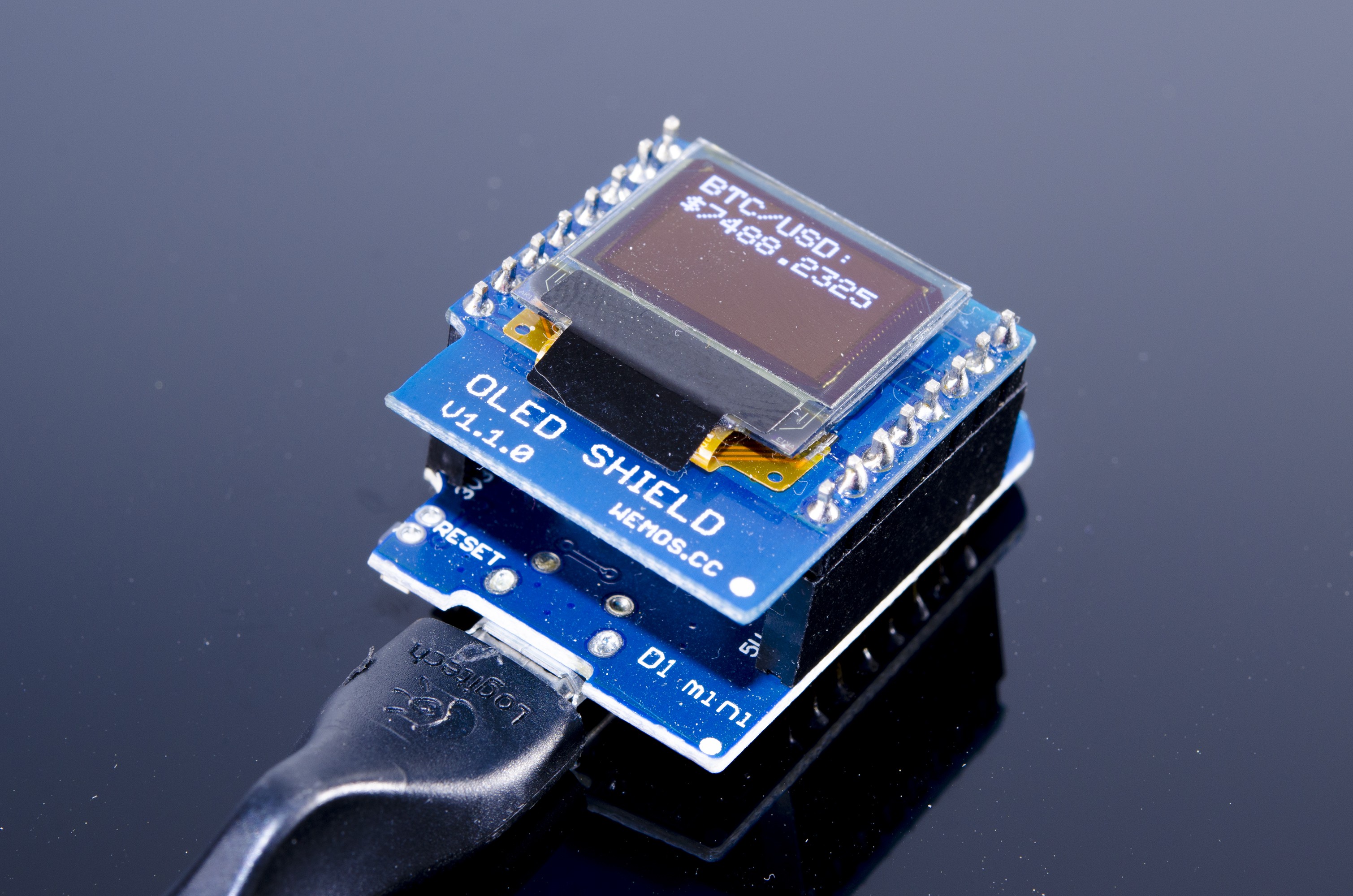
Although the form factor and plug-and-play nature of the WeMos is great, we need to adapt the firmware to use the reduced screen resolution of the WeMos OLED Shield (64×48). Luckily, the SparkFun Micro OLED library works with the shield (uses the same SSD1306 driver), and it is meant for the screen's resolution.
So now, instead of including the "util.h" file, we can simply:
#include <SFE_MicroOLED.h> // Include the SFE_MicroOLED library

#define PIN_RESET 255
#define DC_JUMPER 0 // I2C Addres: 0 - 0x3C, 1 - 0x3D

MicroOLED oled(PIN_RESET, DC_JUMPER); // I2C
This creates the class instance oled, which we can use in the setup() function to configure the hardware:
// Before you can start using the OLED, call begin() to init
// all of the pins and configure the OLED.
oled.begin();
// clear(ALL) will clear out the OLED's graphic memory.
// clear(PAGE) will clear the Arduino's display buffer.
oled.clear(ALL);  // Clear the display's memory (gets rid of artifacts)
// To actually draw anything on the display, you must call the
// display() function.
oled.display();
Lastly, we can modify our printData() function to use the available methods:
void printData(String weather, int font)
{
  oled.clear(PAGE);
  oled.setFontType(font);
  oled.setCursor(0,0);
  oled.print("DATA:");
  oled.setCursor(0,10);
  oled.print(weather);
  oled.display();
  delay(1500);
  oled.clear(PAGE);
}
If we upload the modified firmware, we see the basic data from our prototype, but now in the smaller screen:
Additional software features
Now that we have a functional device, we can focus on improving the UI. Stay tuned for details!
Configurable through a Web Interface [in progress]
[coming soon!]
Weather-based alerts [in progress]
[coming soon!]
Display weather for additional locations [in progress]
[coming soon!]
Show historical weather data [in progress]
[coming soon!]
Additional hardware features
To improve the usability and durability of the ESPecter, a couple of must-haves are battery-powered operation, and a protective case.
3d-printed enclosure [done]
Given our goal of having the ESPicker sit on our desks, we wanted a way to tilt the angle of the display. Thus, we decided to add a cradle to the enclosure so that we could rotate it up and down. The design also includes a clip mechanism for the back cover, which makes it easy to secure and remove it.

Battery-powered operation [in progress]
[coming soon!]
 ACROBOTIC Industries