 Alpha Charlie
-
1Step 1
Front Surface Mirrors
Normal household mirrors use the back surface of the mirror to reflect. For this project we need our mirrors to reflect from their front surface. (Otherwise our projector will have 2 dots instead of 1 as about 10% of the light will reflect off of the surface of the glass.)
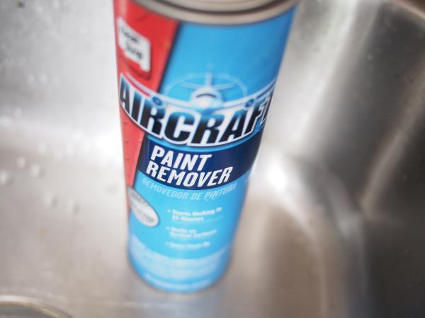
So the first step is to remove the (usually grey or green) backing paint from the 1" circular hobby mirrors. This is done with Aircraft Paint Stripper*.
![]()
* There's a bunch of different stripping products out there. Not all of them will work on mirror backing.
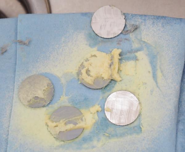
Using glovesand eye protection, spray the back of at least 3 of the 1" hobby mirrors and let them sit for a few minutes. Then using a plastic scraper or old credit card/hotel key, scrape off the softened paint. The photo below shows 2 of the mirrors after scraping.
![]()
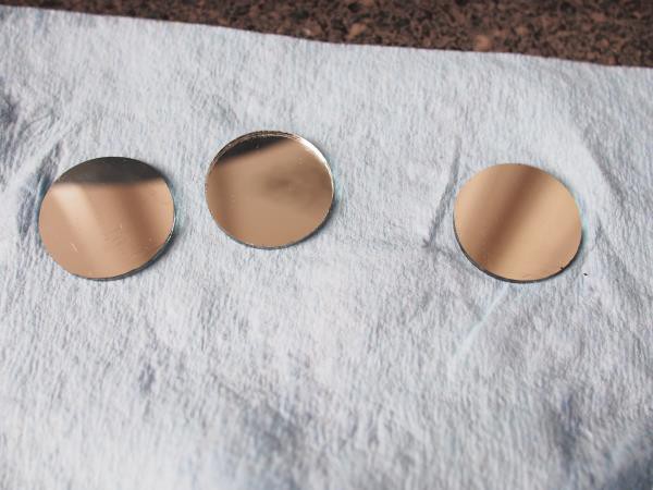
Once the paint has been scraped off, rinse the mirrors with soapy water then dry. There will still be a little 'fog' on the mirror. Using a little bit of acetone (or alternately nail polish remover), gently rub off this remaining fog. After that you can use a bit of glass cleaner or just a little soap and water to finish cleaning up your mirrors.
![]()
Congratulations! You know have some front surface mirrors suitable for projecting LASER beams with!
-
2Step 2
Motors
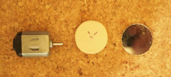
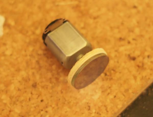
Next we mount our mirrors onto the motors. Since we can't drill holes in the glass we need to use some small 1" wood circlesas backing. First drill out a 2mm hole in the center of each wood circle. Then use 5 minute epoxy to glue the wood discs to the motor shafts and the mirrors to the wood discs.
![]()
Make sure that-
- Do not get any epoxy into the motor where the housing meets the shaft or you'll seize the motor
- Do not use superglue/CA. Use epoxy. Cyano-acrylate will fog the glass.
- Do try to get the mirrors as straight and centered as you can. Even though we are relying on them wobbling to make our pattern, if you try to make them wobble, it'll be too much. Plus if the weight is too far off the unit will vibrate. Just get them on there mostly straight and don't sweat it.
![]()
The finished motor/mirror assembly.
-
3Step 3
Motor Mounts
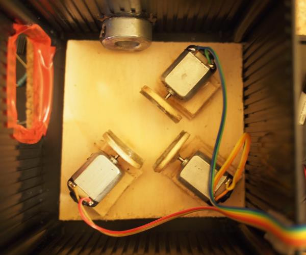
Next we want to make the platform that the motors mount to. To do that, first take your 1/8" plywood (or plexiglass) and cut 9 x 1" squares and one 3 1/2" x 3 1/2" square. Glue the 1" squares into stacks of 3, then arrange each stack of 3 so that the mirrors form a 'U' shape with just enough space to spin without the mirrors touching. (see picture).
Below you can see the inner workings. Light enters from the top, then reflects around counter-clockwise 270 degrees until it exits through the large aperature on the left.
![]()
Glue the 1" squares to the base, but do NOT glue the motor/mirrors on yet. Let it all dry.
-
4Step 4
Install Motor Mounts and Align Mirrors
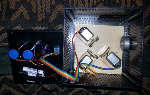
Next we install the motor mounts into the case. I just used 2 sided tape so I can re-align it or repair it if necessary. (You can glue your in if you want though.)
Once the motor assembly is installed in the case, the next step is to drill the hole for the LASER pointer. The hole should be 12-13mm depending on your laser pointer. It should line up with the first motor mount (the bottom left one in the photo) both horizontally and vertically. The center of the hole should be about 7/8" from the bottom of the box. THe collet shown in the picture is optionl but will help align the LASER.
Now the motors can be installed and aligned. Pointers -
- insert the LASER pointer in it's mounting hole and turn it on.
- With the LASER pointer on hot glue or epoxy each motor in place starting at the bottom left and moving counter-clockwise. Each mirror should deflect the light 90 degrees.
- The mirrors should form a 'U' shape when looked at from above. Use the photo as a guide. When done the LASER should be projecting on the left inside wall of the case where we'll cut our hole for the beam to exit.
- You want to align each mirror so that the beam hits at it's center at approximately a 45 degree angle and reflects to the center of the next mirror
- You want the mirrors as close together as possible. But make sure they do not touch when spinning
- Avoid touching the mirrored surface of the glass as it's no longer protected by paint. It's easy to scratch or fog
- The biggest thing to make sure of is that the beam NEVER runs off the edge of the mirrors. The path gets wider and wider, so in practice you only have to worry about the last mirror
-
5Step 5
Mounting and Wiring Components
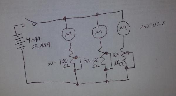
Next you'll want to drill holes for the 3 potentiometers and the switch. Positioning is not critical as long as they don't interfere with the mirrors. Once that's done you can wire the motors, pots switch and battery holder as follows -
![]()
The schematic is very simple with each pot controlling the speed of one motor. Be careful that the wiring does not interfere with the path of the beam.
![]()
-
6Step 6
Exit Aperture
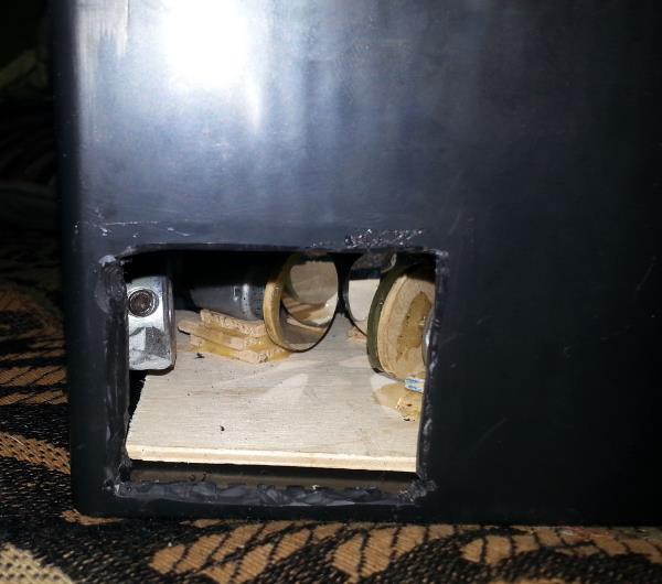
Now that it's wired you can install some batteries and turn it on with the lid off and it should project the light show onto the inside of the case. Note where it projects and mark where you'll cut the exit aperture. You'll want to cut an extra couple mm so that the edge doesn't cut off the LASER pattern.
![]()
The photo above shows the rough-cut exit aperture.
LASER Pointer Light Show
A simple 'Spirograph' style LASER light show using mirrors and motors and potentiometers.
Discussions
Become a Hackaday.io Member
Create an account to leave a comment. Already have an account? Log In.