pj
pj-
Raining on my parade!!
09/22/2016 at 20:52 • 0 comments![]()
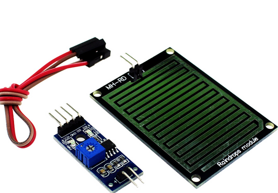
I have just purchased a Rain sensor for 50 pence (UK money) - nothing right!
I have this idea about having a rain sensor outside and my HoCo system telling me (buzzers, strobes maybe even a voice command mmmm that is an idea) that it is raining after I have gone and put my washing out to dry!
This introduces a new type of sensor, namely, a non-fail-device. You see, all my sensors are in my system to tell me if something has happened (water too high, water too hot etc). Well this type of sensor (above) does not have a fail state. It only comes into play if another sensor and itself is in a certain state. For example if i have my washing out to dry AND if it is raining. So how can I achieve this. Well, simple really, as I have designed such a nice modular system. I will attach to a new project box a rain sensor and a couple of buttons and a couple of led lights.
This is how the sequence will work.
- I take the washing outside and put it on the line. I will press button A on the node.
- The node will send a msg to the server saying "button A on node09 has been pressed"
- The server will record the status of button a in the devices file. All is well!
- It starts to rain and the rain sensor sends a value to the node and the node sends a msg to the server ".. it is raining"!
- The server puts two and two together and if button a has been pressed it will send messages to buzzers etc
QED! (or have I missed something? - I always think this if something has worked out rather too easily!)
![]()
-
How can I tell my curtains are closed?
09/19/2016 at 19:02 • 0 commentsI was thinking.....
I would like to know that an actuator has actually done what it is to have supposed to have done, like switch on a light or closed the curtains or switched on a pump etc etc. It would be good to know that it has done what it should have and to that end I am wondering how I could do it.
It seems that the test is going to be different for each actuator.
To check to see if a light has been switched on a light sensitive sensor would be the thing to use.
To check a pump is working a flow-sensor is the thing to use.
But how can I (cheaply and simply) actually litteraly check to see if my curtains have been closed or opened? (I have actuator driven curtains in my Lounge which close and open by switch)
Idea 1 ) May be a light source and a light sensor and when the material has broken the beam (permanently) then they are closed, and if the beam is not broken then they are open.
Idea 2) Have a switch mounted at the top of the curtain rail so that when the clip (that attached to the start of the curtain run) touches the switch it switches on (sprung) and when the curtains draw away from the switch then it switches off. So Off means Curtains are open and On means Curtains are closed.
Idea 3) may be a light sensor close to the curtain rail so when it goes dark the curtains are closed. (mmm this could have problems in a dark room unless the light sensor is extremely sensitive)
Idea 4)..... over to you guys... have you any ideas? please write them below - thanks :¬)
-
"Device?" are you ok?
09/18/2016 at 21:22 • 0 commentsWhy is it that I get these ideas in the bath? LOL.
As part of the software I have a database for each sub system, (Aqua, Home and Burg) (Aquariums, Home, Burglar alarm)
In the database I have a table called Devices
(I use SQLite3 for speed, safety and ease of use. Python works well with this integrated library)
The records are (similar to) this
devid = tnk1flt1
live = 0
srvr = Server01
node = Ardu01
minv = 0
maxv = 0
wait = 0
desc = tank1 float1
cont = 9
next =
type = S
stat =
They identify each device on the network of devices on my system.
(These records are for sensors and actuators. I can record the status of each of the actuators as well because I want this system to be able to work 100% if I have a computer crash; I want the system and the computer to start as if nothing has happened - I don't want anything held or left in memory!)
The above entry, for instance, is for Float sensor-1 in Aquarium-1.
devid = unique name
The live is 0 (0=inactive, 1=active. so I can stop a device from being processed by the system. )
srvr is the mqtt broker server is called Server01
node is the Node where the device lies (*1) is called Ardu01 (each node is a project box with an arduino or nodemcu that has any number of devices attached to it. The devices can be sensors or actuators. Float sensors, flow sensors, temperature sensors, etc and pumps, heaters, lights etc)
minv and maxv are the minimum value it can be is 0 and the maximum value it can be is 0.
The wait time that it must be checked (Every 0 minutes) (0=don't wait to recheck) (*2)
desc is a small description
cont. The checking program must continue with a flag of 9 (I will tell you more about that another day dear reader)
next means when it is allowed to check this device again. (another sneaky field of data I will explain another time)
type is for what type of device it is (A for an actuator and S for a sensor) ($ is for a non-fail device, see note (3*) for this one)
the stat field is for actuators. (1=on, 0=off) (i.e. curtains; closed=0, open=1) etc
Anyway... as I get a msg from the Node (arduino or nodemcu or whatever) saying that the device has given a reading, the program resident on that node checks if the reading is within the min and max levels. If it isn't then it send a mqtt message to the broker saying so. The python program resident on the main computer (it's called "sentinel" - coz it sounds flash!) picks up this message and then acts upon it.
SO
I was thinking! (in the bath) what if one of my devices is sick/has broken/been eaten by the dog etc etc?
My sentinel program would not know as it is a passive program that just waits for mqtt messages advising of certain conditions.
SO
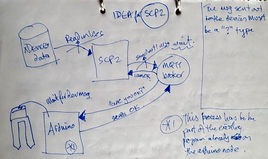
I am designing another program (haven't thought of a cool name for it) (answers on a postcard please) (all answers considered LOL)
This new program will use the devices list as explained above. It will go through each record and send out a special type of mqtt message (with an action code of $) (have i explained to you dear reader about the format of my mqtt messages yet? No? Really? OK I will do that some day soon) When these devices pick up a "?" type of mqtt message it will then send back an information mqtt msg with an action code of "!" (>=Action, !=Information, ?=Query, $=Status etc) So this new program will pick up that msg and "all will be good"..... unless of course the device does not return a msg and then all is NOT WELL, so the program will go into meltdown mode, and start buzzing buzzers, flashing lights, sending emails and all sorts of overkill stuff!
Another addition to this program could be using the sensors to see if the actuators are actually working. Let me explain... Let's say that the daylight-sensor says it is now going dark then the logical conclusion to this would be to send a msg to the curtain-actuator to close, and update the devices record. That part we have got - yes?, ok. Now, if we attached another sensor to the curtain machine to actually check that the curtain closer has actually closed... now... that would be very cool. We perhaps could have a status display on our main screen showing the statuses (statii?) of all the devices and underneath each device text we could display the sensor's text to see if the device is working. Something like this...
+----------+----------+
|*tnk1pmp1*|*tnk1led1*|
|status=on |status=off|
|*tnk1flw1*|*tnk1lsn1*|
|status=on |status=on |
| ALL OK   |***FAIL***|
+----------+----------+
as you can see in the first display box there are two device's information. the left box on the top there is *tnk1pmp1* (tank1 pump1) and the status says it is on (this piece of data was updated when the pump was told to switch on). Underneath that is another device called *tnk1flw1* (tank1 flow-meter 1) and that is reporting that it is on so, all is ok. However, let us look at the box on the right, the device is *tnk1led1* (tank1 led lights1) last time it was switched off the device file was updated with OFF... but... the device underneath that is *tnk1lsn1* (tank1 light sensor1) and that sensor is reporting that it is ON so this is a FAIL STATE!. Perhaps we could buzz and flash and email etc. Sometimes I think that this is a bit overboard but considering the fact that I am not actually next to me automatic fish tank system all the time and there is possibilities of a water malfunction for instance it would be very good if i could get to know about it for not that much effort on my part. What do you reckon dear reader?![]()
(*1)
I will explain a little of my terminology here just in case I have forgot elsewhere and to give you a little reminder.
the server. There is only one on my home automation system and it is, at the moment, a SBC (Single Board Computer) called an Odroid. The O.S. I run on it is linux mint. I have my IoT MQTT Broker on this server. It is named SERVER01. It is a small fanless circuit board with a load of stuff on it and it cost me £50 as at September 2016. This will live in my cupboard under the stairs with the rest of my other network and comms equipment.
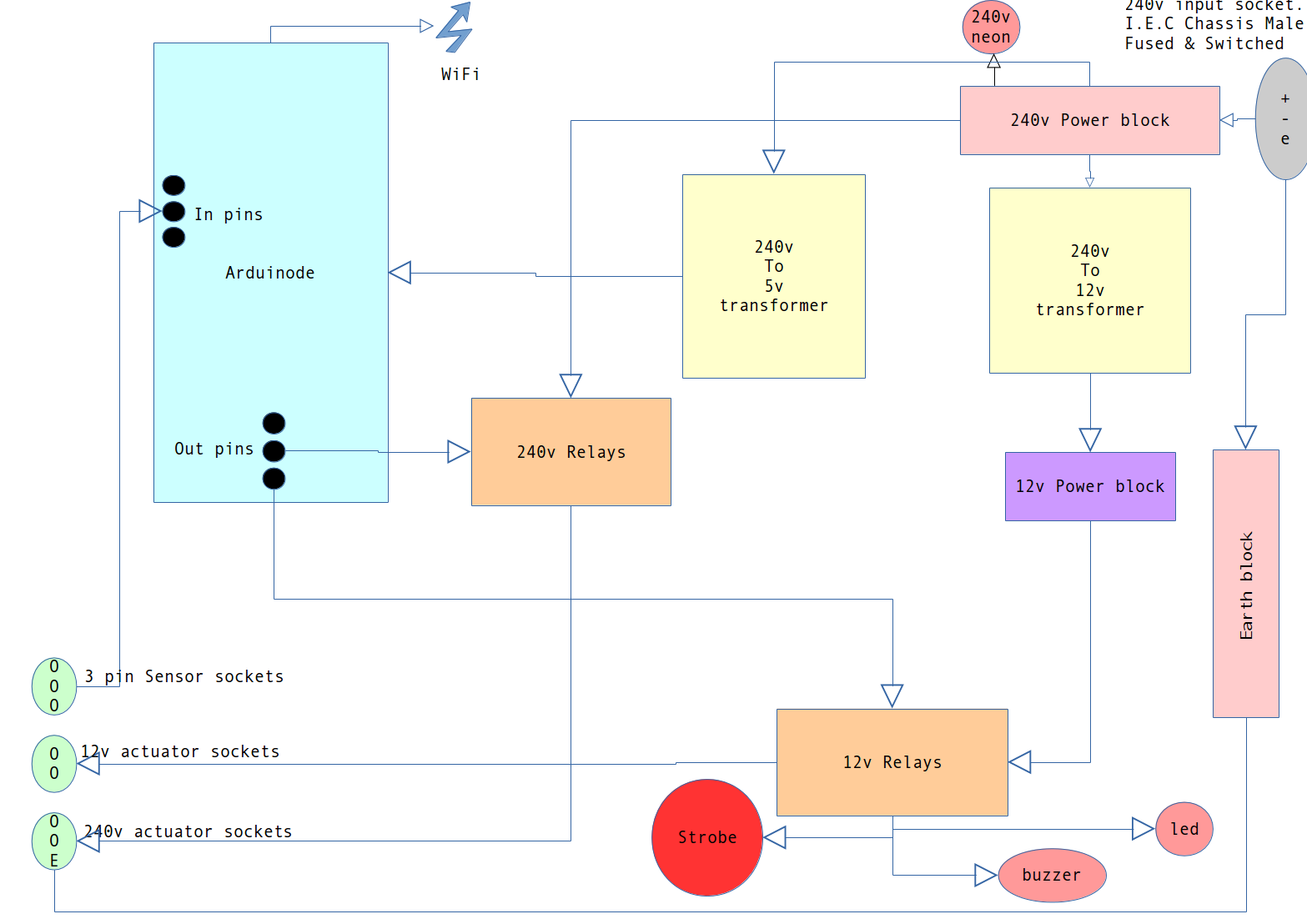
the node. There will be many nodes on my home automation system, (which by the way has been titled as HoCo) (Home Computer System). Each node will be a largeish project pox with an Arduino or Nodemcu in it. There will be a couple of power supplies, a few relays, a couple of LEDs and a few sockets ready for any sensor or actuator that will plug into it. I have different sockets for for different devices for safety. It will be mains driven. Each node is named aaann where aaaa is either ardu (for an arduino) or nmcu (for a NodeMCU) and n is a number in sequence.
![]()
the device. A device is an Actuator (pump, light, strobe. bell. switch, heater, curtain closer etc) or a Sensor (light-sensor, humidity-sensor, temperature-sensor etc). A node can have more than one device. Each device is named aaanbbbn where aaa is the general descriptive collection abbreviation (e.g. TNK for Tank, LNG for Lounge, RES for water-resevoir etc), n is a number in a sequence . bbb is the descriptive name of the sensor/actuator (e.g. PMP for pump, FLT for a float-sensor etc) and, again, n is a number in a sequence. So, for example, tnk1pmp1 is pump number 1 in thank number 1, another example would be LNG2DOR3 Lounge number 2 and door number 3.
(*2)
There is going to be time where I dont want the system to keep on re-checking a device after the code inside the node says that a particular device's value is unacceptable (e.g. the moisture-sensor says that a flower pot's soil is too dry). The reason that I dont want to keep on re-checking the device is that after I have switched on a pump, say, for a few seconds to water the said flower pot, it will take a few seconds/minutes for the water to seap through the soil. And, if not ignored, the pump will keep on watering the soil and cause a problem. The same reasoning, for instance, could be if the temperature of the tank water is too cold. (Forget for the minute i have thermostat controlled heaters). If the system got the message the water is too cold then the system would switch the heater on. This process would repeat switching on the heater.
SO
I have built in a design for a wait scenario. Once the device has flagged up that there is a problem I update the INI devices file with the next time that checking can continue.
The wait entry in each record is the number of minutes to add to the current time.
The next entry in each record is the time when checking can be resumed.
Phew - I hope you got all that!
(*3)
I have now invented a 3rd type of device. I call it a non-fail-device, that is, it is a device that does not fail like normal sensor-type devices could. Examples of non-fail-devices are light sensors and outside-rain-sensors. These just simply record the status of something. But, as my logic for arduinodes are to send messages of their status and values etc then these NFD's (non-fail-devices... keep up!) are to send message of their status too. So, if I need to find out their value I will read the devices file as this will be updated when the sentinel program receives their message - get it? No! what do you mean no! it is as clear as, erm, mud. :-(
-
Dropbox
09/18/2016 at 20:58 • 0 commentsWhat a great idea I have just had! (I don't get that many folks!)
I am going to run my project software within Dropbox. As it is a syncing service and the files are resident on my computer(s) it is a fab idea to run it from with Dropbox directory (we (older folk) always used to call a collection of data files in a computer a directory. Windows (yak!) renamed it just to be hip and called it a folder. I still call it a directory as it should be. (Stamps foot on ground!). Sorry I digress. Where was I ? oh yes Dropbox.
These are the good points for running the software within the Dropbox folder - erm - sorry - directory!
- Backing up data and code
- Viewing current status files remotely
- Remote fixing and maintaining code
- Editing s/w anywhere on any of my computers ( I work away from home in two locations ) ( That's why I am doing this project - so my fish get fed and plants watered).
Bad points for running the software within Dropbox
- haven't thought of any yet (as @ 18 sep 2016)
![]()
-
Sorry this is log out of date-order. It should be July 2015.
09/14/2016 at 11:09 • 0 commentsJuly 2015. I started this project in the summer of 2014 and stated to my
flat mate that it will take a year to build. Well here I am a year
later and not of lot of building has been done. I have bought most of
the kit and sorted out where everything is to go but as I am not a
project person and has never successfully actually finished a project
the whole thing is overwhelming me. I want it to work perfectly and look
great so I dont want it to be a cobbled up mess as my poor fish deserve
better :)
-
Code written and more designs. 14 Sep 2016.
09/14/2016 at 11:06 • 0 commentsHere I am on Tuesday September 13th 2016 and not much has been physically built but I have written something like 1000 lines of code. Written in three different computer languages namely, Python, Bash and Arduino-Sketch.
I have had some success attaching a water temperature sensor up to a nodemcu so I know I can do it (well... just!).
As I am an analyst/programmer I set too and tried to design something to see if i could get a Node mcu and an Arduino to send MQTT messages back to a central p.c. (Will replace P.C. with a raspberry pi or an ordoid at a later stage to shrink things down.)
Success!. I have been able to get the arduinode (as I am now calling them) to send (publish) mqtt messages to the mqtt broker on the p.c. and I have a python program resident on the p.c. subscribing to these messages - doing some calculation on the message (like temp too hot etc) and then sending new messages down the line for the arduinode to pick up, to, say, switch on a pump or a fan etc. Sorry, I am not explaining myself very well. Anyway that is the protocol I am going to use so that all my devices communicate over the same way. Sending message to and from each other. It is the way I am going to do my IOT (Internet of things) project. I hope it will expand so i can maintain the system over the internet at some stage. My first internet connection will be for the p.c. to send me an email if there is a problem (like tank overflowing! or similar - eeek!)
I have written a lot of the infrastructure now as I know I can get msgs going to and fro' and the devices that need to listen are listening and the devices that I need to talk are talking. I have written and re-written programs to try and standardise as much as possible and use industry standard formats like using JSON styled data structures and reading and writing of INI type files. I am using LInux as an operating system on the P.C. - it is easier for me as I know this system well and it is better than Windows. (in my opinion) (No flames please).
The design of the hardware has come on a notch too. Each Node (!) (see below) will have a project box with an arduino or a nodemcu in. Each box will also have a few relays, a power transformer from 240v to (approx) 5v, a connector block, a few leds (for information purposes) and a few sockets.
The overall system design is to have a passive server and an active node... I will explain...
I have thought about the number of messages going to and fro through the system and what it could do to my Intranet in my house (I share the network with 3 mobile phones, 1 internet TV and 4 computers). To this end I have now decided upon a passive server and an active node system. The server's code will be .... wait and wait some more until a msg comes in from a node.
The server will then decide if the message is for it and then decode the message (e.g. in plain English I mean.... I am the temperature sensor in the tank1 and the temp is to low). Once the server has decoded the msg it will then act upon it. E.g. Send message to Node2 to switch on pin3 which will then trigger a relay which will then switch on tank1-heater2. The Active Node system means that it reads the values of all its attached sensor devices. (Sometimes there will be only 1 sensor and sometimes more). Each node will have a small amount of intelligence in as much it will know if the value returned to it from the sensor is not within acceptable limits (E.G. Temperature high is > 25 or < 20) If it is not within limits the node then sends a msg over the network. (This is hard to explain sorry). This device will keep on sending msgs until the sensor value is within limits.
Now, sometimes a situation will arise when the sensor value will not change immediately (E.G. The water is not warm enough - switch on the heater - this will take quite a few minutes) So, with this is mind, when the first occurrence of the msg arrives at the server - code will be updated to when the next time that the server will read a message from this sensor.
I have designed this system this way so I can integrate another two systems into this with very little work, namely... my household (lights, curtains, garage doors, emails etc) and a Burglar Alarm system (door sensors, bells, strobes emails etc) and they could all work hand-in-hand if I wanted them to (E.g. Fish tank overflowing - sound off the alarm system ! )
All that would be required is a project box like the one below (or smaller/larger whatever) a small piece of code in the arduinode to define the acceptable sensor limits (E.G. On/off or door open/closed or Daylight-level low so draw the curtains etc etc etc) and some extra code in the server to act upon the msg. (E.G. Close the curtains, switch on the light, sound the alarm, switch on the strobe etc etc)
((I feel this project will last for ever and that worries me as I am a bit of a protagonist))
(((I am moving house aswell sometime in the future so this lot has to be uber-portable)))
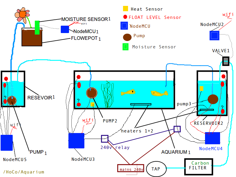
Overall design of the Aquarium and water system. You will notice (below) that the end result of the tank water is to water a few flower pots. (Which is really why I am doing this whole thing!) (Just to see if I could!)
![]()
![]()
-
Have I had my head in the ground? {NODEMCU}. Watering my plants from aquarium water via signals from this chip.
12/10/2015 at 10:06 • 0 commentsWhere have I been? Why have I not heard of this product before?
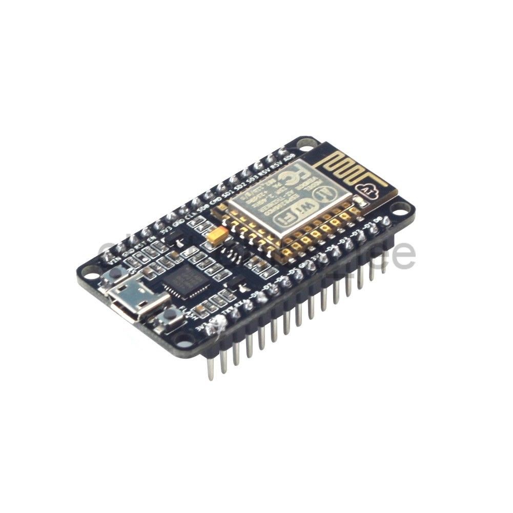
It is called a NODEMCU (pic below) and it incorporates the ESP8266 wifi chip. (I paid about £10 for it with carriage from eBay)
![]()
It has a small micro-processor chip on a board with a Wifi chip. (plus voltage regulator and mounting board etc) I have just received it today (2015-12-10)
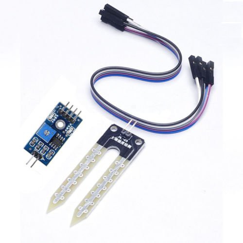
It, apparently, will alleviate me having to buy an arduino with wifi shield for my "Soil moisture check project" {As of Dec2015 I have not yet published this on my home automation project log}. I can now fix a moisture sensor (pic below) (also from eBay) to this little beauty and (with 3.3v of power) I can send the result straight to my IoT (Internet of Things) server running on a raspberry pi via WiFi !!!
![]()
So, all (!) I have to do is:
- write a little prog (with assistance from the web)
- upload it to the NODEMCU
- power it up
- attach the sensor
and I will receive {on my raspberry pi} little messages on the IoT server saying something like... "Sensor=1, 80.00" or "Sensor=2, 05.00" meaning, of course, sensor 1 = 80% humidity or sensor 2 = 5% humidity.
You may be wondering, dear reader, why am I interested in this being part of my Auto-Aquarium, well, the waste water from an Aquarium (during auto-water changes) is full of nutrients and I use it to water my plants with. They LOVE it. So as part of my auto water changes I will keep an amount of this waste water. When my Raspberry pi realizes that my plant pots are dry (via the above NodeMCU sub-project sending in IoT messages) it will pump some of this nutrient-rich water to the plant pots, probably about 10 seconds worth of water via a mini pump (a timed amount in order to stop problems of overflow problems).
-
Fish feeder idea
12/10/2015 at 08:21 • 2 commentsHi people.
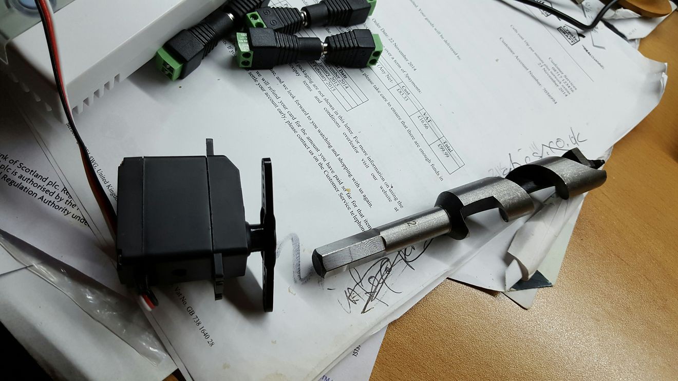
I have come up with this (half) idea for the fish feeder (cribbed from other people).
![]()
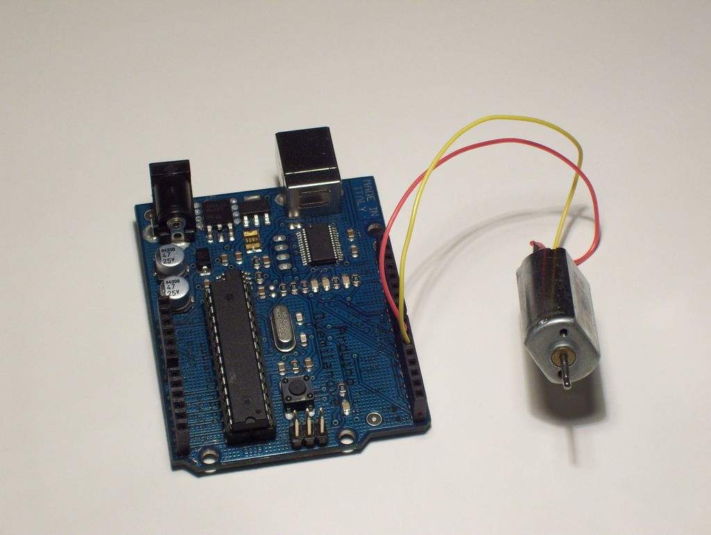
I need to come up with some way of attaching the drill bit to the motor blade.
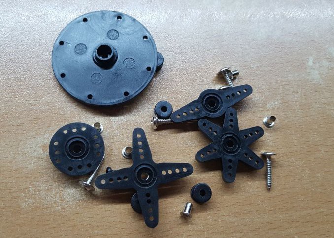
I got these bits and pieces with the motor...
![]()
... so I am hoping that I can attach one of these bits to the drill bit.
ANYBODY GOT ANY IDEA PLEASE? I think an idea may be to put the drill bit through the width of a plastic cereal box.
![]()
It is a bit of a rubbish idea as, an electronics-guy I am but, DIY-guy I am not.
Maybe I should use the spring and plastic tube idea instead. I am totally lost. :¬(
-
Fish feeder. (Help required please)
08/01/2015 at 20:32 • 2 commentsI am still thinking how I am going to build a fish feeder. I have looked at as many as I can and they wont do for me. I am not a builder so this part is not going to be easy (unless one of you guys fancy helping me in this bit).
What my spec is:
- It has to hold enough food for at least 4 weeks for at least two, possibly three, tanks full of fish.
- It has to be guaranteed to work.
- It has to receive a signal from an arduino (probably via the PWM method) that will pass a number which will equate to an amount of food. I.E. If the design is an auger and a motor it would be sent, say, "4.5" which would equate to 4.5 seconds for the auger to turn.
- It has to pass the fish food into a water tank, via gravity or perhaps another (?) method.
Ideas would be very welcome, thanks.
![]()
![]()
-
Most of the electronics bought
07/20/2015 at 07:24 • 0 comments- Most of all the electronic components are now purchased.
- I have written code for most of the monitors and actuators.
- I am going to use IoT (Internet of Things) ethos so I am going to use an MQTT server on my raspberry pi as well. To this end I am now finishing off the python and arduino (C+) code to speak and listen to the server.
Aquarium controller / home automation
I am building an automated aquarium controller to fit into my home automation system.