-
1Step 1
Gather your parts / Tools
You will need:
- All the parts listed in the components section above
- Small phillips head screwdriver
- USB cable with Mini-B connector
- A computer to program your Arduino
- (optional) USB 5V Charger to power SAB3T when not connected to PC. -
2Step 2
Coil Your Wires!
![]()
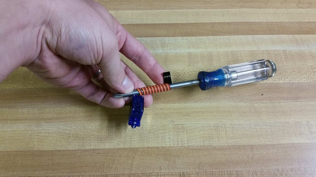
Grab your 2 servos and the touch screen wires. Wrap them tightly around a cylinder, such as a screw driver.
![]()
When you let go the wires will relax a little bit and should slide right off the end of the screwdriver. The wires hold the coiled shape which makes routing them later look much cleaner.
-
3Step 3
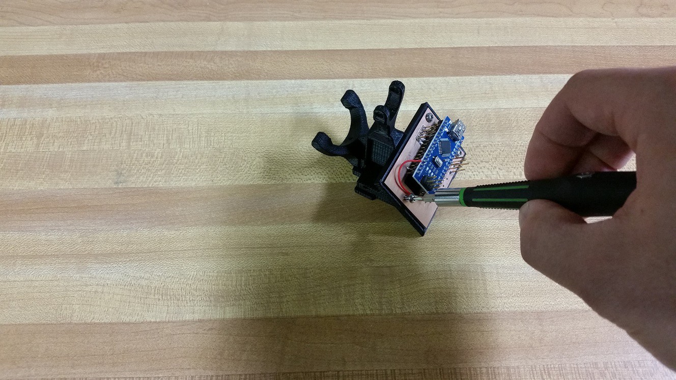
Install the Arduino
![]()
You need:
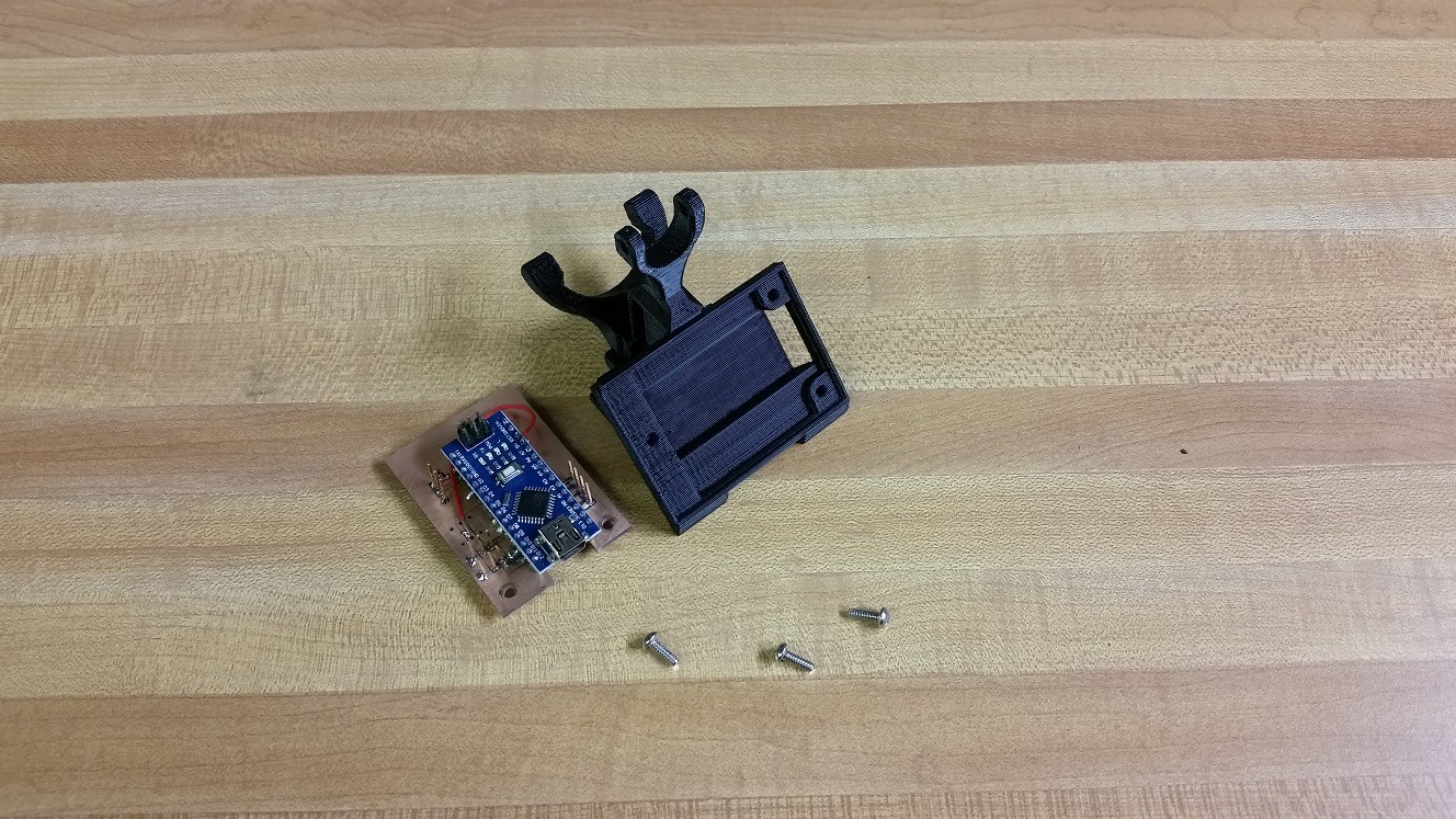
- Arduino (soldered to interface board)
- 3 screws
- 3D Printed Central Tower![]()
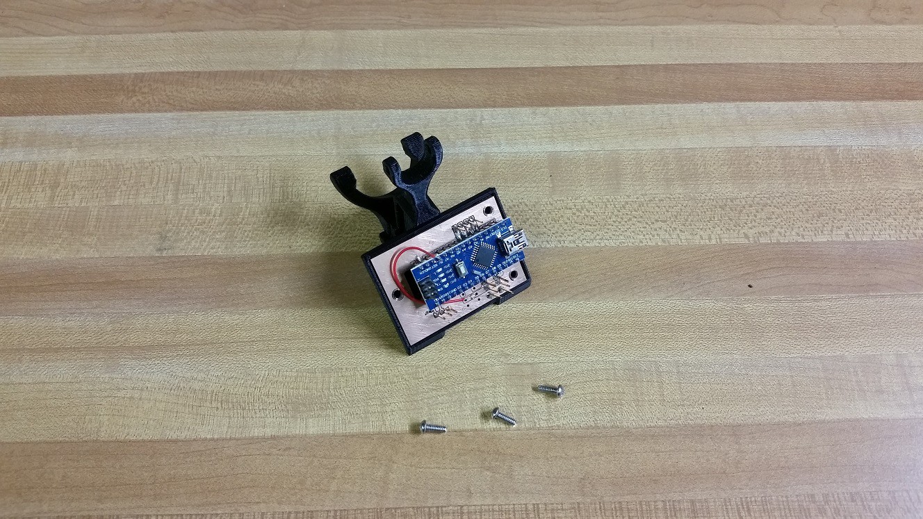
Install the Arduino oriented as shown. There are only 3 screw holes so it will only go in one way.
![]()
Screw it in! The holes in the 3D print are sized so that the screws will self thread, so the screws should go in with a little bit of resistence.
-
4Step 4
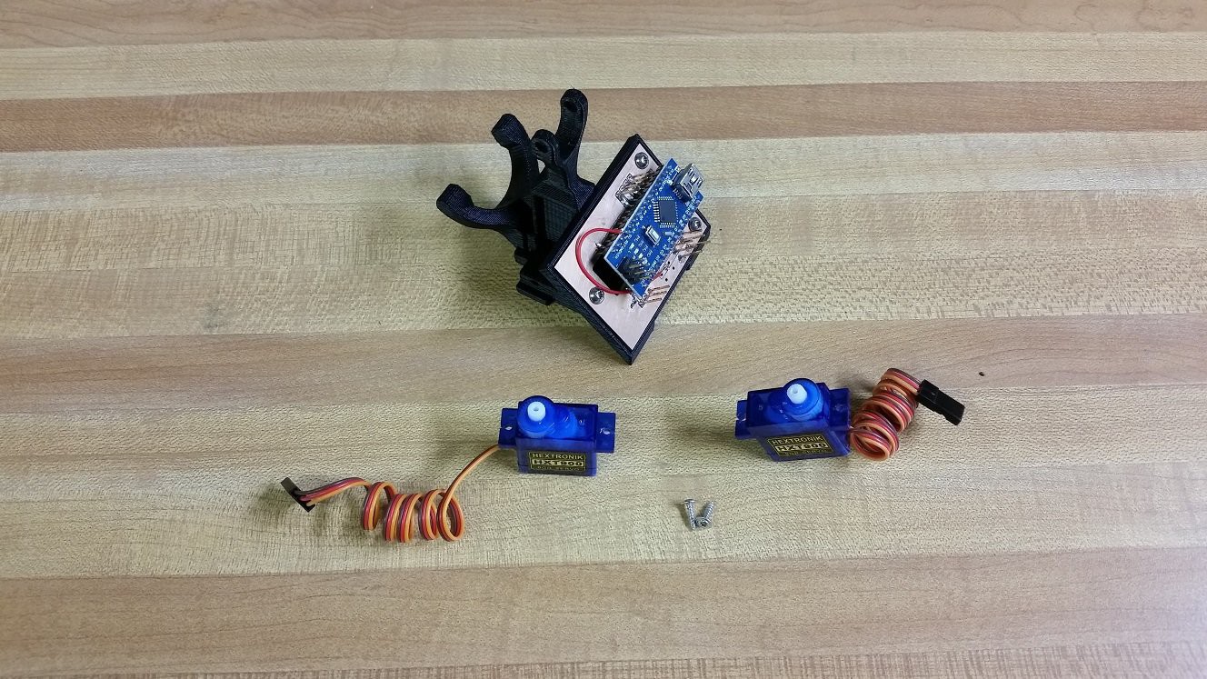
Install Servos
![]()
You Need:
- Assembled pieces from the last step
- 2 Servos
- Two of the long mounting screws that came with the servos![]()
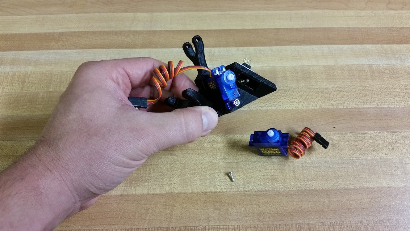
Orient the servo so that the wires exit on the top. Slide the servo into the recess in the Center Tower. Use one of the screws to secure the servo as shown.
![]()
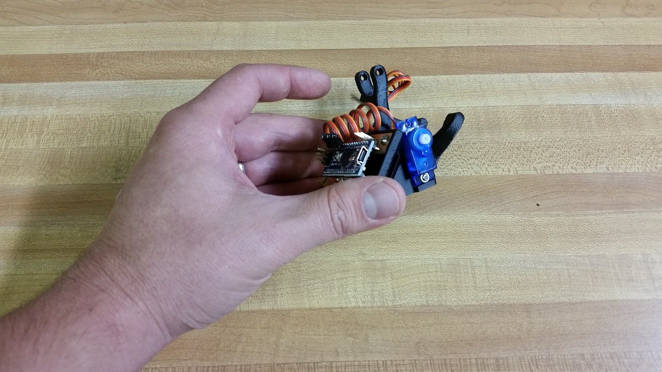
Repeat for the other servo on the opposite side of the Central Tower
![]()
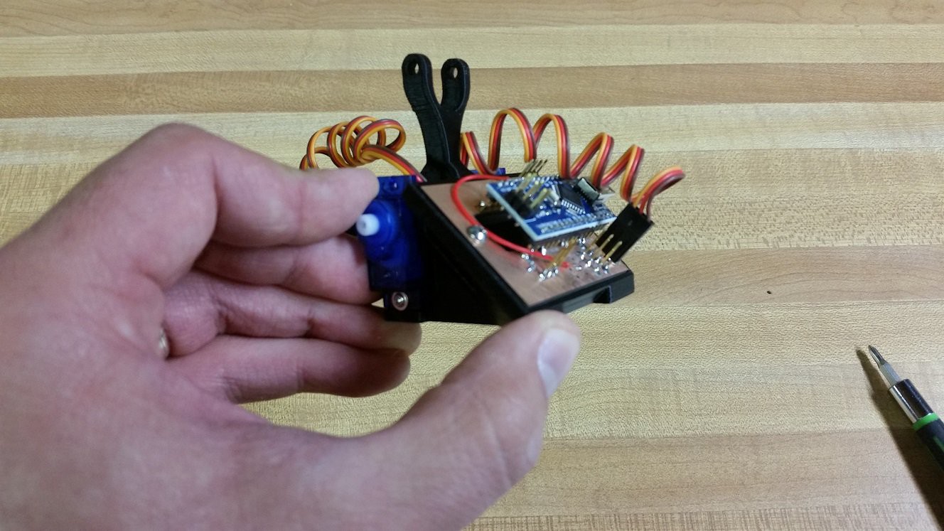
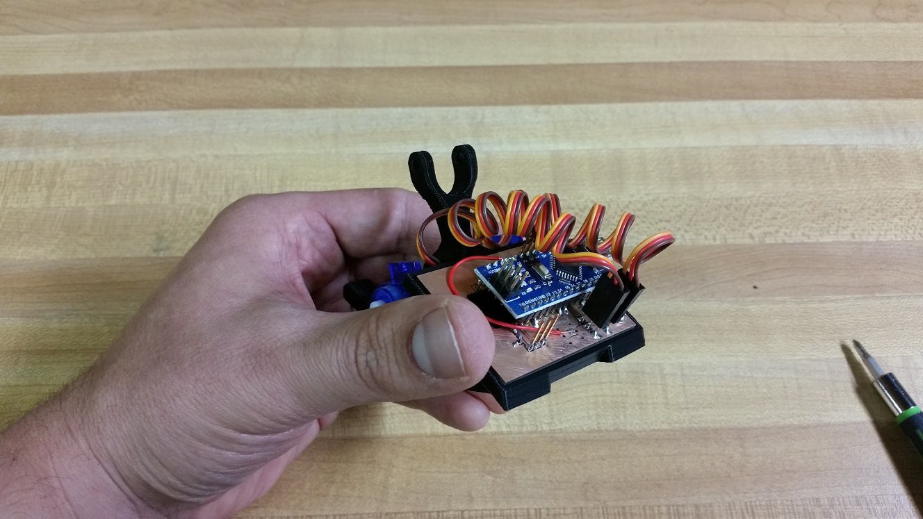
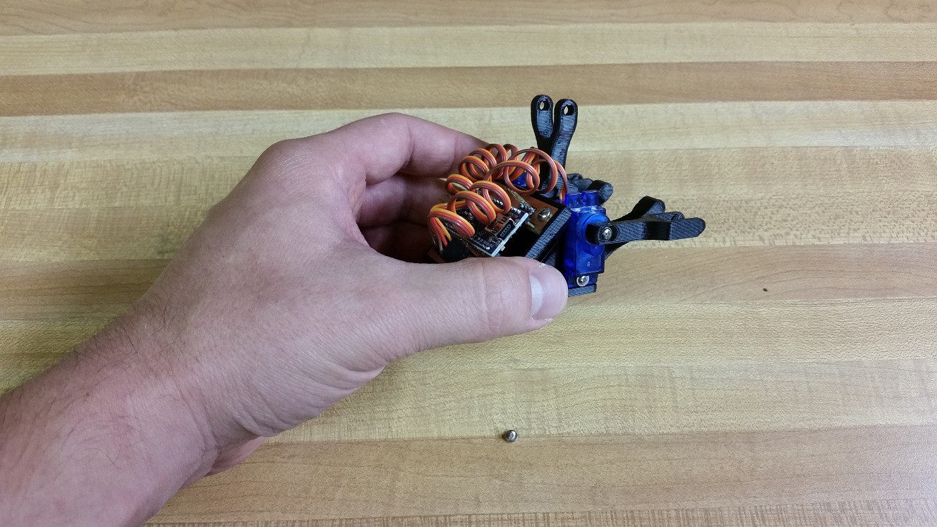
Next connect the servo lead to the Arduino Interface Board. There are 2, 3 pin headers below the Arduino near the USB port. Connect the Left side servo to the left side header, connect the Right side servo to the right side header. Orient the connector so that the brown wire is farthest from the Arduino; orange wire closest.
![]()
-
5Step 5
Program the Arduino
Head over to the Github for SAB3T (linked to above in the project) and grab the arduino code.
Use the Arduino IDE to load the code. I'm having you do this now becuase the arduino will move both of the servos to thier center position as soon as it starts to run. You should hear them move a few seconds after programming.
Note: The Arduino Nanos that I shipped in my "Best Product" prototypes use the CH341SER chip. If your OS doesn't detect and install the correct driver you can find it here: http://wch.cn/download/CH341SER_ZIP.html
-
6Step 6
Install Servo Arms
![]()
You Need:
- Central Tower with all the stuff you already put on it
- 2 Servo Arms
- 2 Servo Arm screws. They are the small screws that came in the bag with the servos![]()
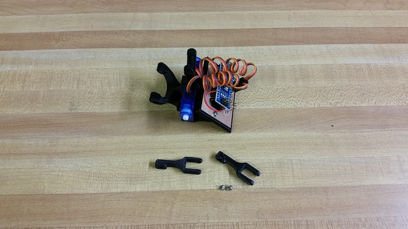
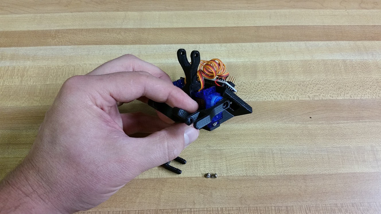
Install bother servo arms so that they are horizontal. Don't worry if you don't get them perfect. Later on we will calibrate out any imperfections.
![]()
Install a small servo arm screw in each of the servos to secure the servo arm.
-
7Step 7
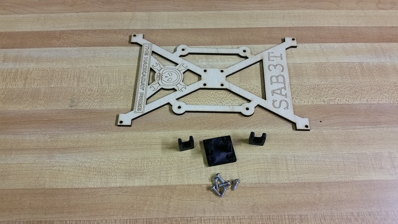
Touchscreen Bracket Hardware
![]()
You Need:
- 2 ball link ends
- 1 universal joint mounting plate
- 1 touchscreen bracket
- 6 screws![]()
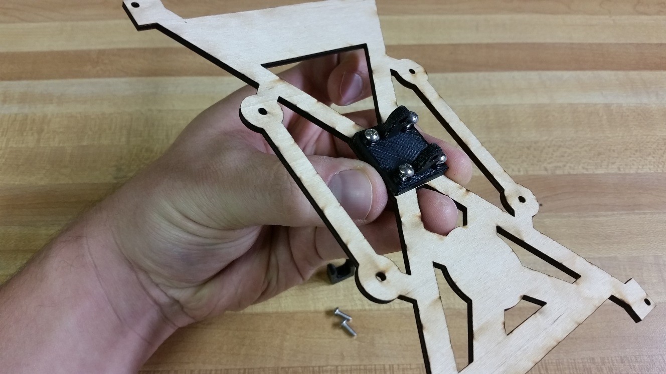
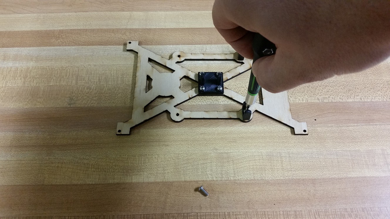
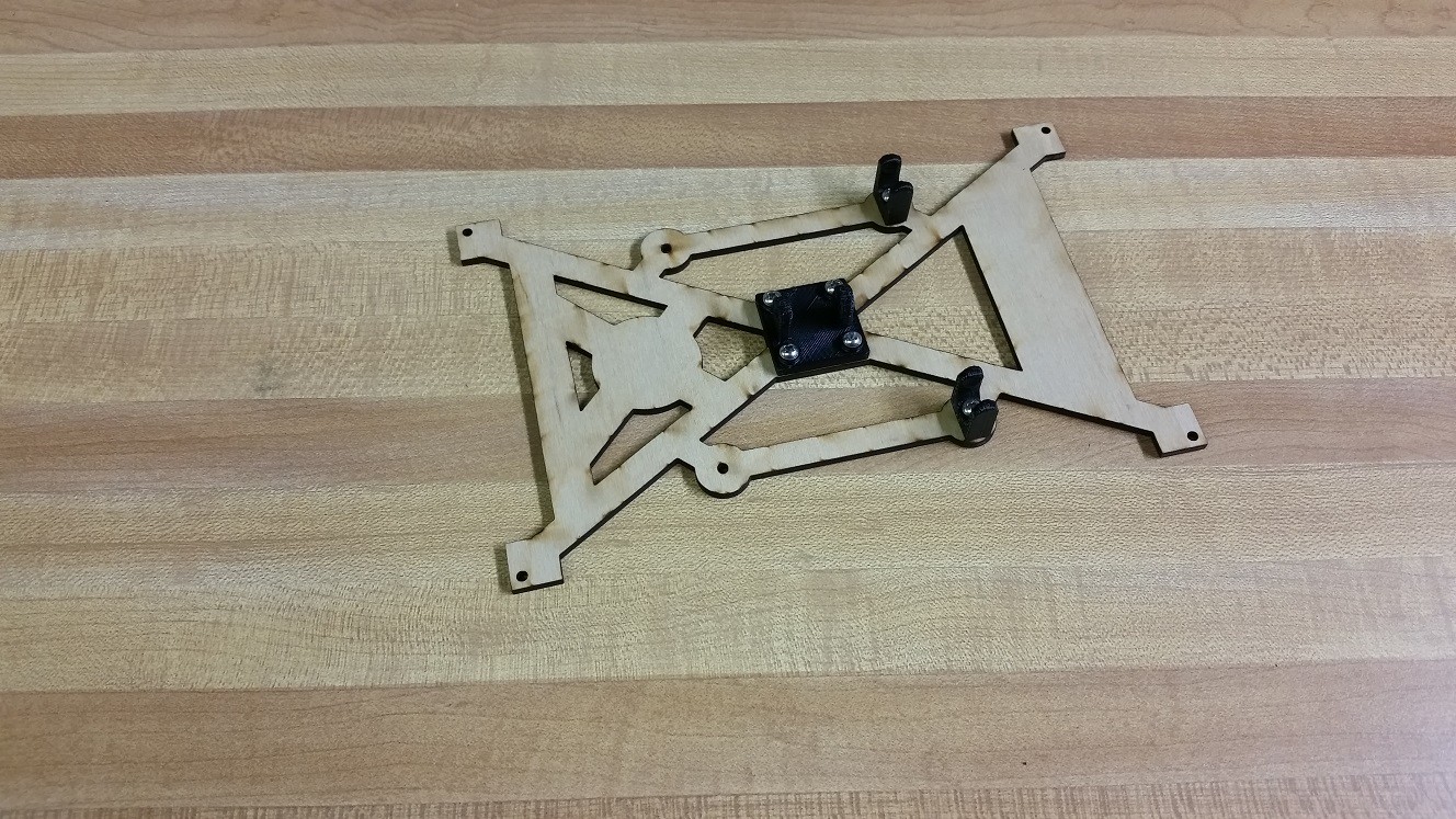
Start with the universal mounting plate. Make sure to orient it as shown in the picture above. Screw in all 4 screws. The holes in the wood are sized so that the screws will self thread into it.
![]()
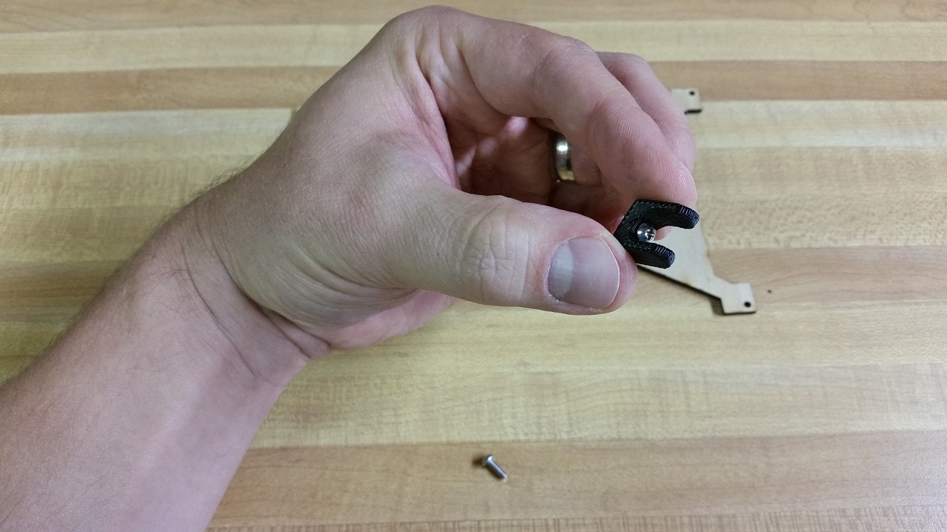
Next up is the ball link ends. I find it is easiest to put a screw in it first, then line it up with the appropriate hole in the touchscreen bracket. Otherwise the screw is hard to insert.
![]()
You will want to put ball link end mounts on the same side of the touchscreen bracket. Above I'm putting them both by the "SAB3T" label. There are holes on the "HaD Prize" logo side to that will work just fine.
![]()
-
8Step 8
Universal Joint 4 Way
![]()
You Need:
- everything from the previous step
- universal joint 4 way
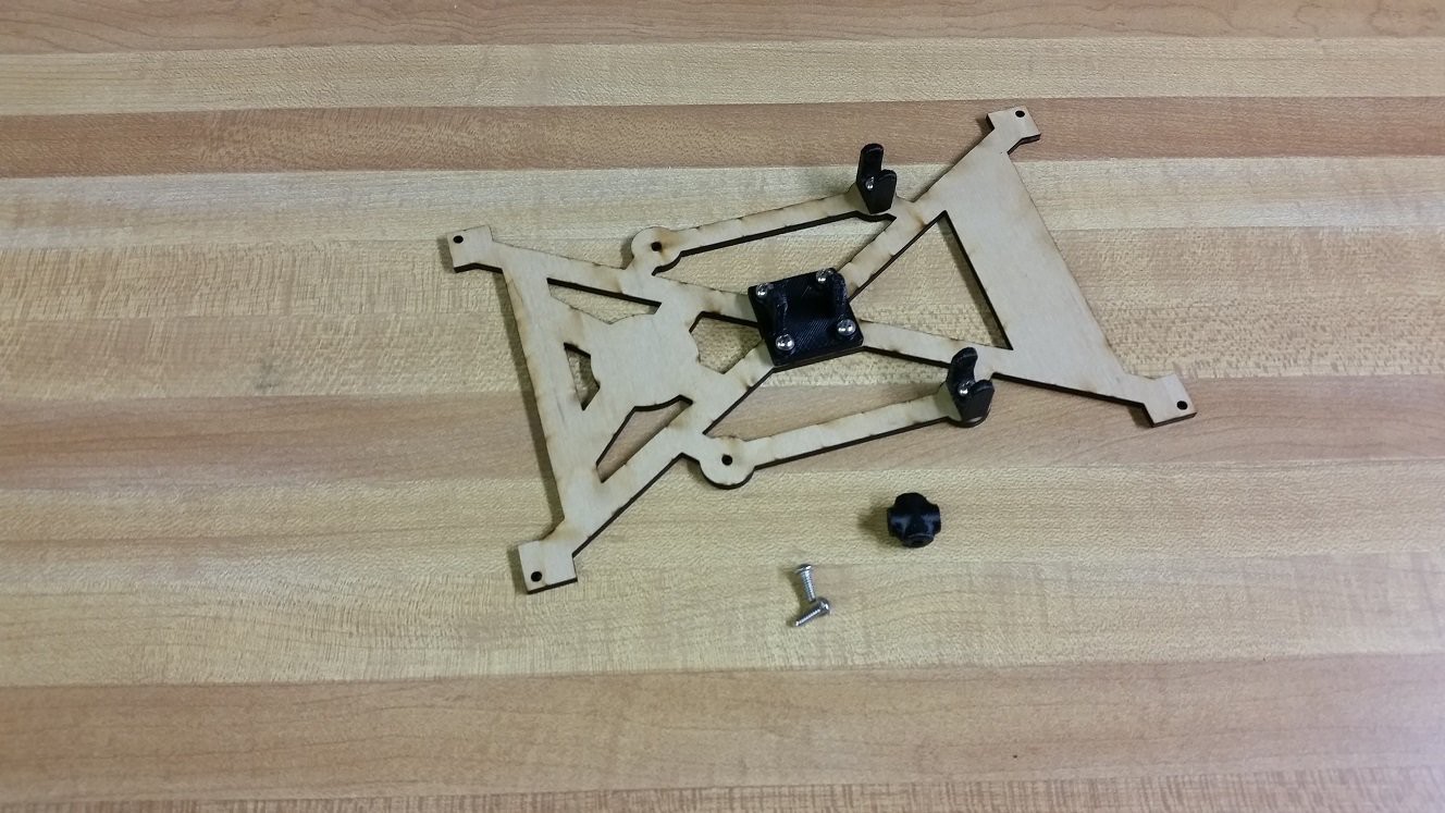
- 2 screws![]()
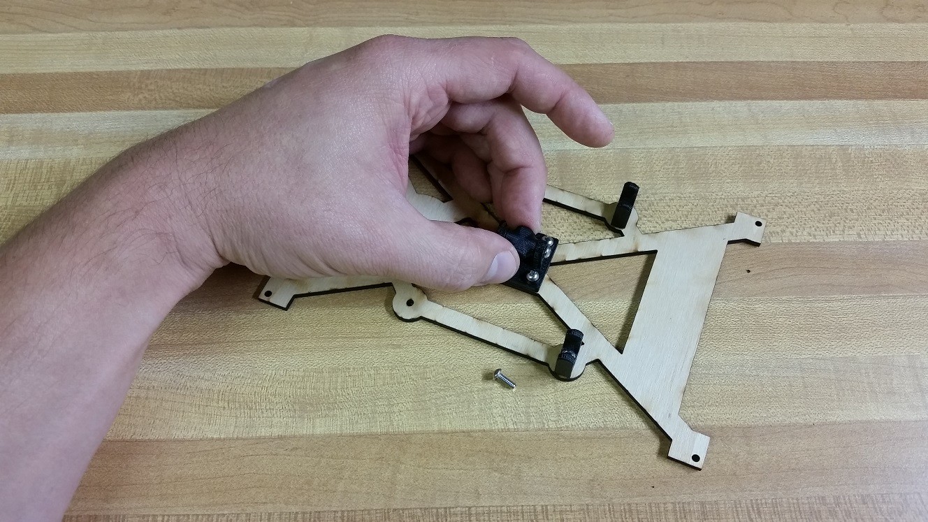
The holes in the universal joint mounting plate are slightly larger than the holes in the 4 way. This will allow the screw to spin freely in the mounting plate but be threaded into the 4 way.
Install both screws so that they are still a little loose. You want to 4 way to still be able to turn freely.
-
9Step 9
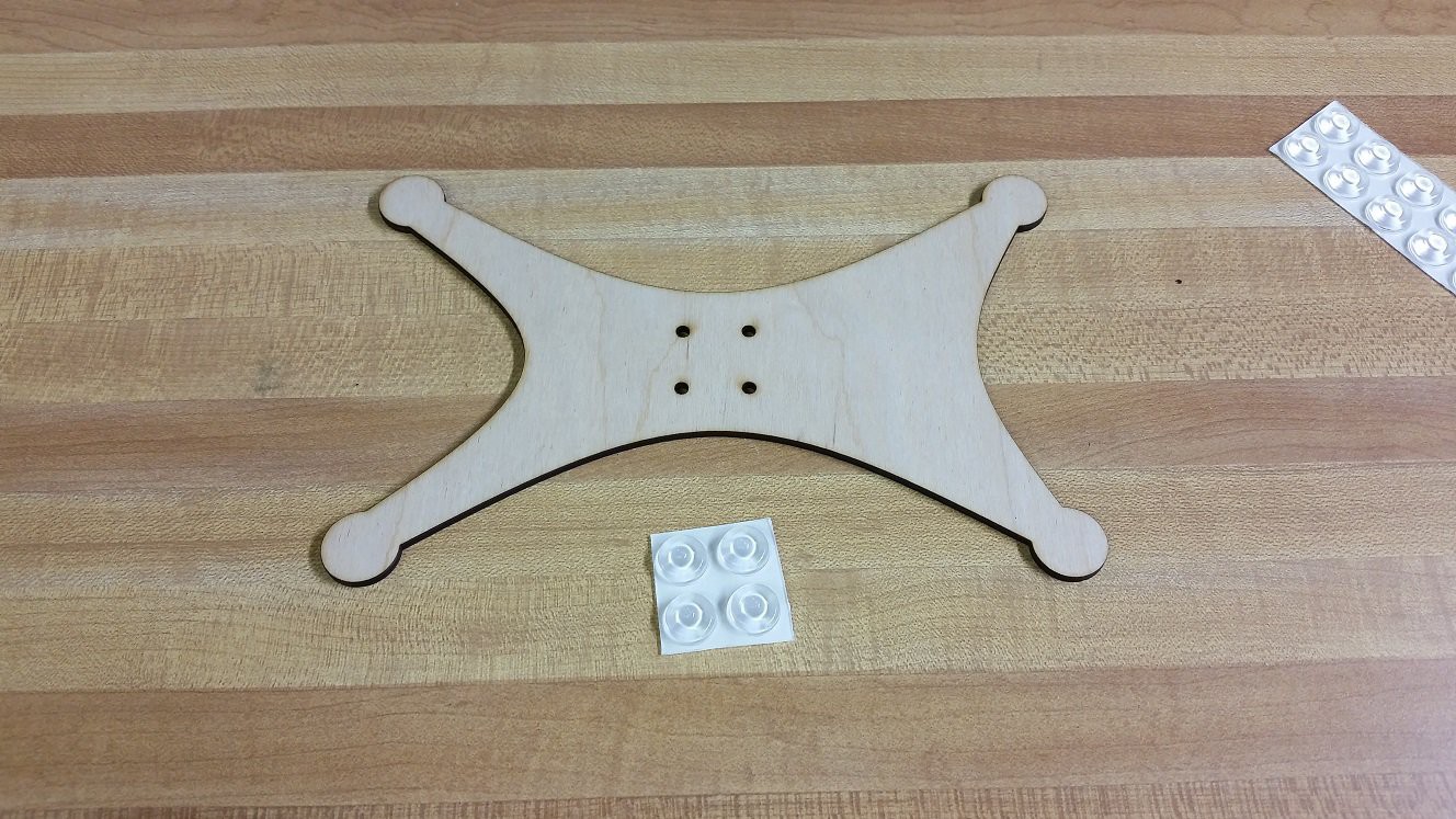
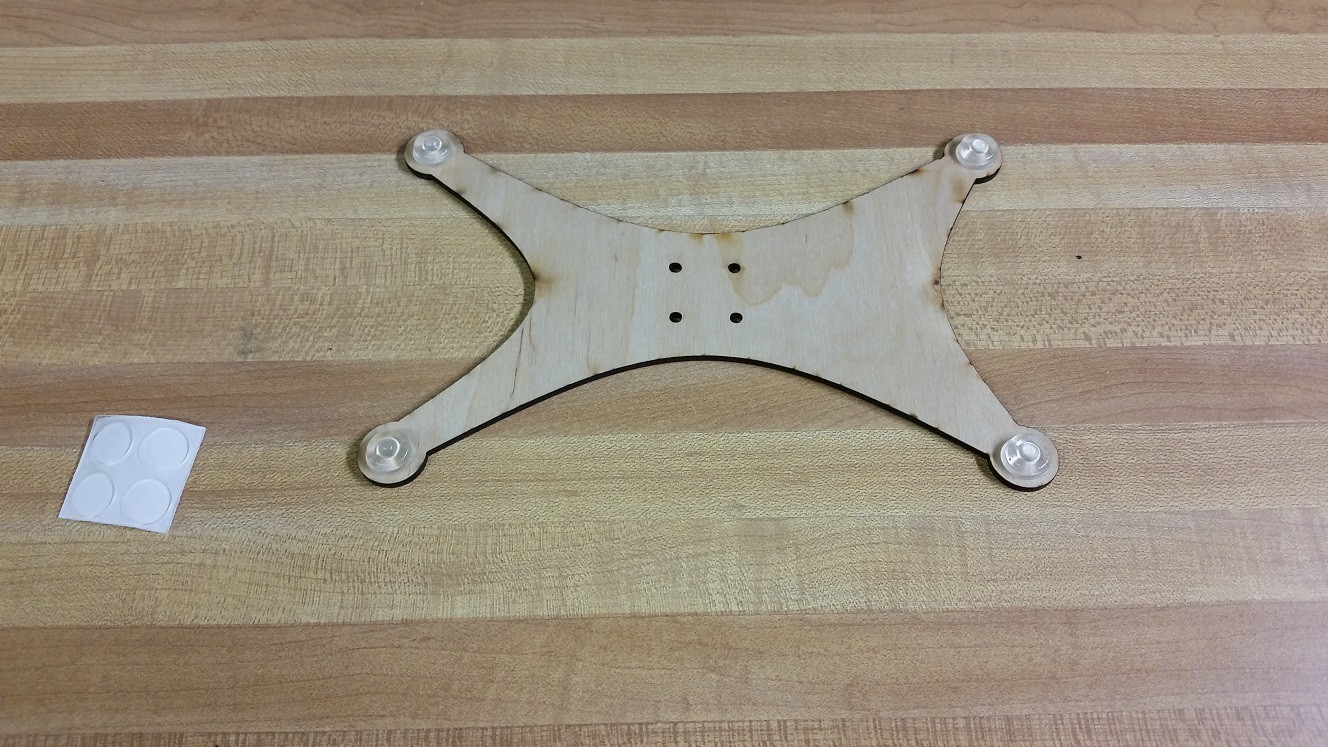
Bumpers and Central Tower
![]()
You Need:
- bottom plate
- adhesive bumpers![]()
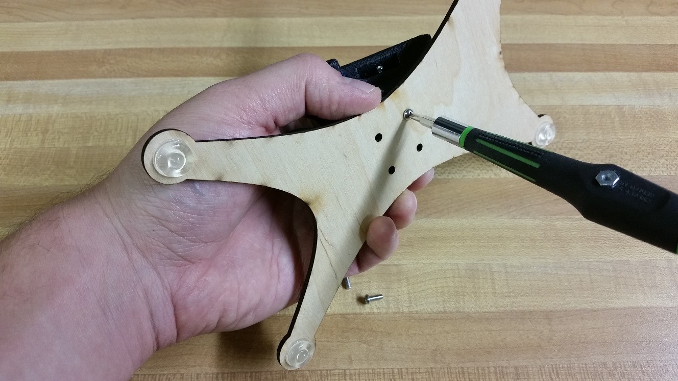
It doesn't matter which side of the bottom plate you stick the bumpers on, but I prefer to do it on the side that had a little bit of discoloration on the edges from the laser cutter. Peel each bumper and stick it to each of the corners as show above.
-
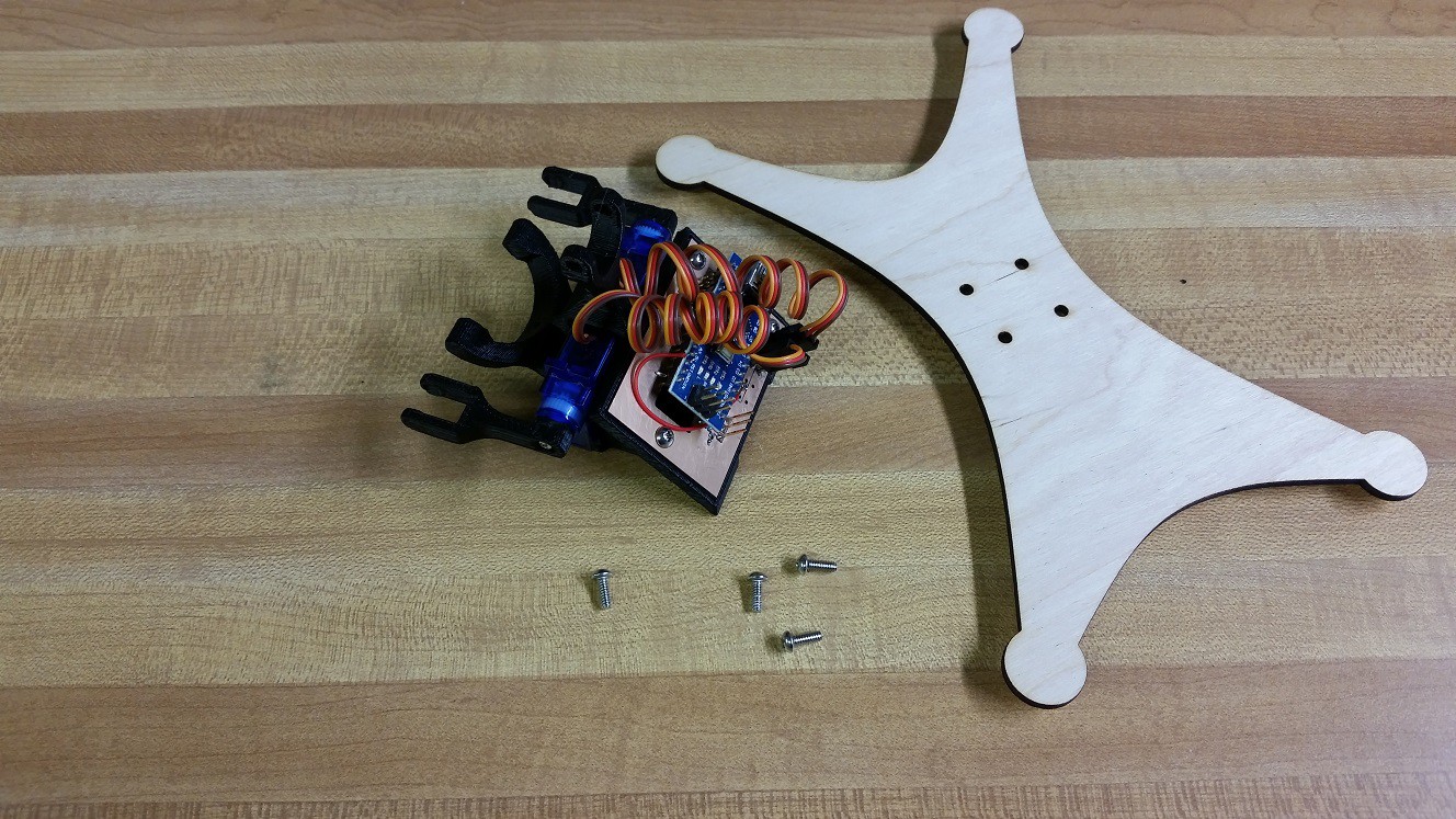
10Step 10
Central Tower
![]()
You Need:
- bottom plate with bumpers installed
- central tower with servos and arduino installed
- 4 screws![]()
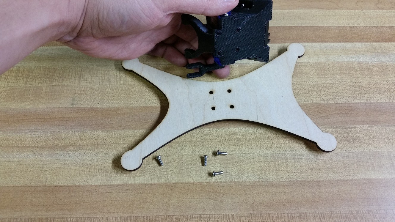
If you look at the bottom of the central tower you will see that there are 4 holes which match up with the holes in the bottom plate.
![]()
The holes in the bottom plate are slightly larger than the holes in the central tower. This allows the screws to self thread into the central tower. Attach all 4 screws.
Note: Current the bottom plate is not symmetrical. In the pictures above you can see that the right side is wider than the left side. This is an artifact of the earlier designs of SAB3T and doesn't currently serve a purpose. Originally there was a separate plastic holder for the arduino that was screwed into the wider section of the bottom plate. The latest revision of SAB3T integrated the arduino mount into the central tower, but I didn't change the bottom plate. It will work fine with wide section of the bottom plate facing either direction.
SAB3T - PID Loop Educational Tool
Learn how to use PID loops for fun: SAB3T - Servo Actuated Ball Bearing Balancing Touchscreen.
 Tim
Tim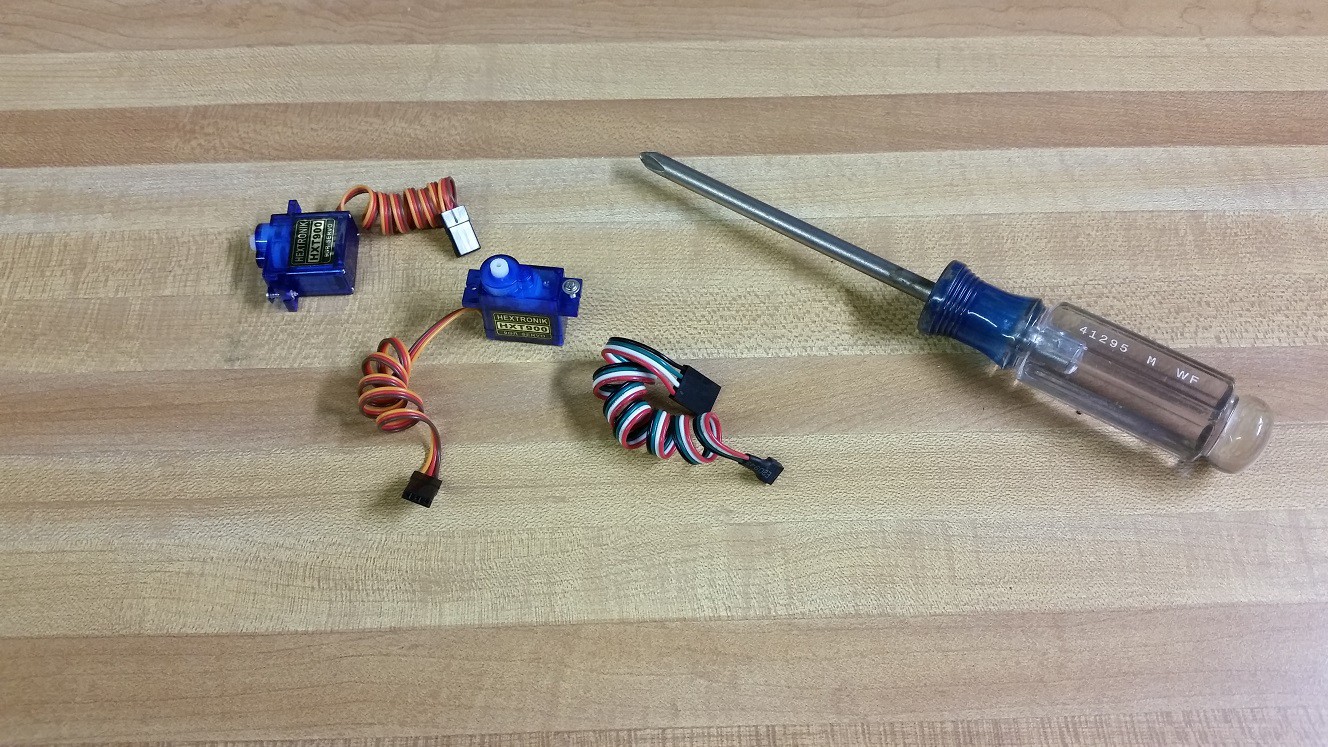
Discussions
Become a Hackaday.io Member
Create an account to leave a comment. Already have an account? Log In.