-
1Step 1
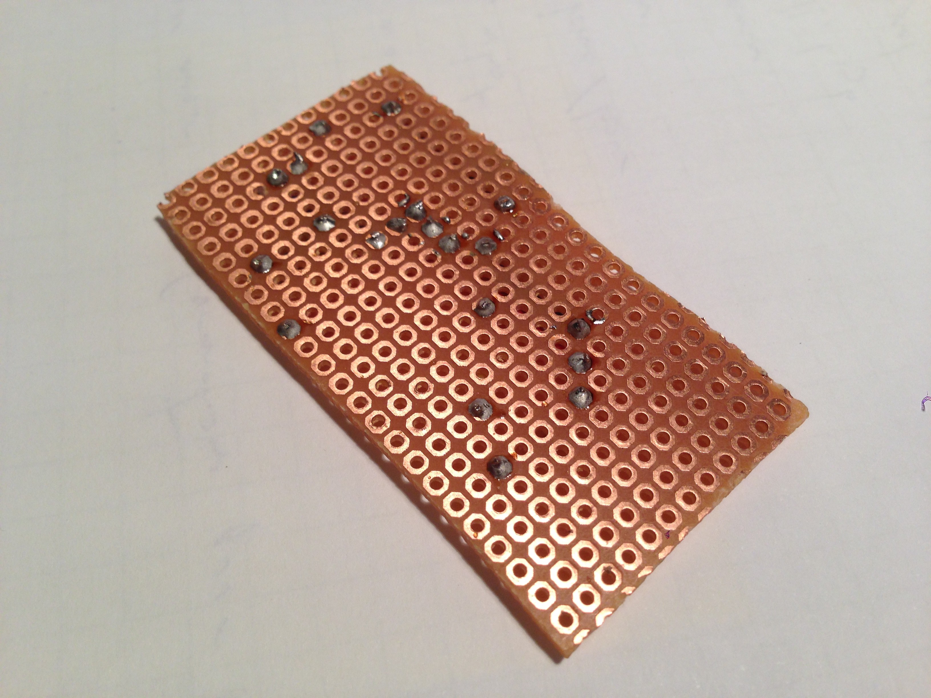
The first step is to prepare the perfboard, it should have a size of 23 by 12 holes.
![]()
-
2Step 2
Prepare the wires and place them on the perfboard like so. The color code here is:
- Red: VCC (3.3V)
- Black: GND
- White: signal (SCL)
- Blue: signal (SDA)
- Green: signal (MOSI)
- Yellow: signal (button)
- Resistor: 10kOhm
![]()
-
3Step 3
Solder everything and cut the excess.
![]()
-
4Step 4
Solder all the traces. It may be easier to refer to the PCB file than look at this picture. Note that all the holes where the electronics go are left free for now.
I realised later that it might've been easier to solder the electronics first and then the traces... do whichever way you think is best.
![]()
-
5Step 5
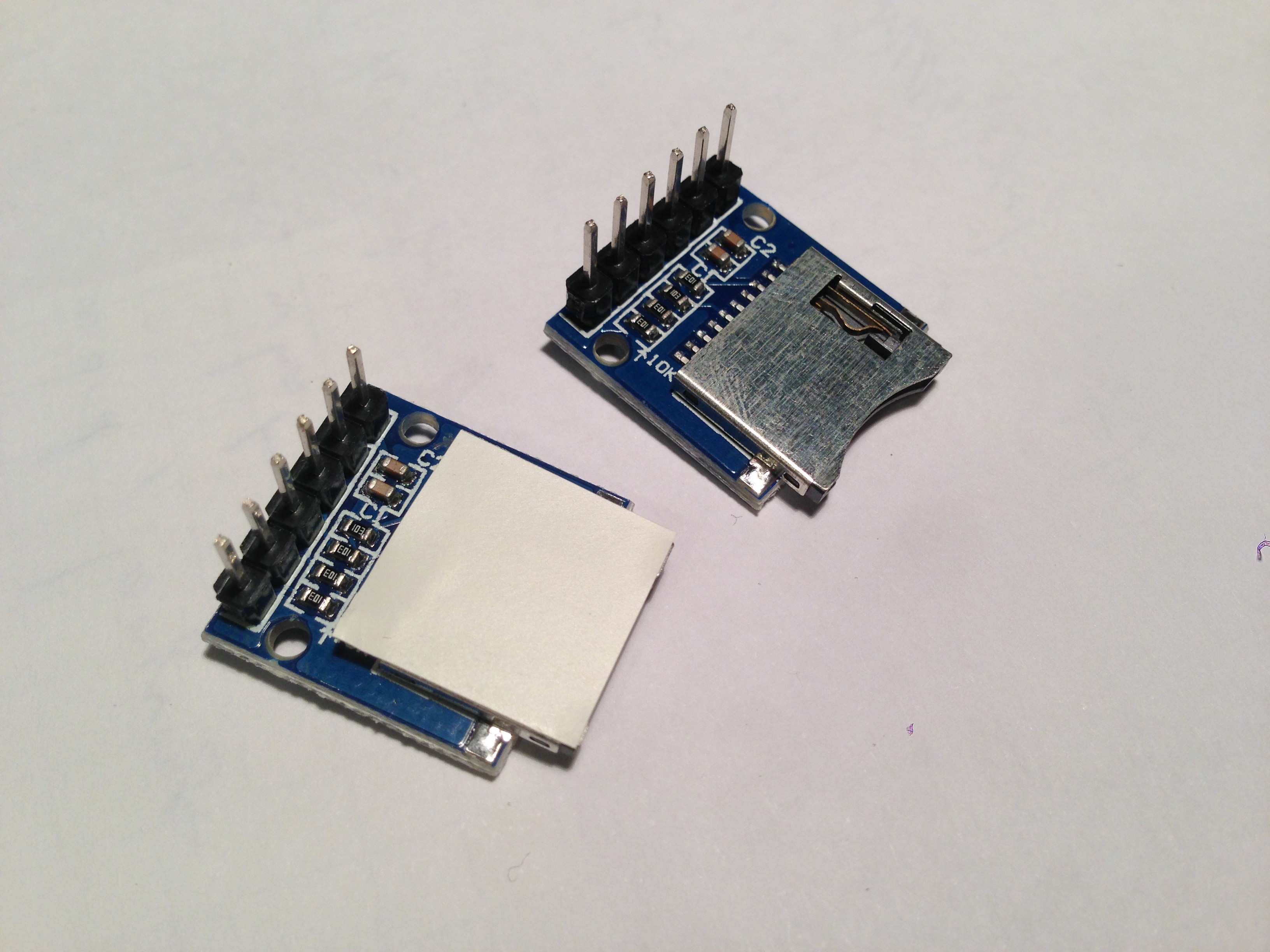
Attach some electrical tape on the SD card reader, the metal part is close to the I2C lines going to the OLED screen and it might short them otherwise.
![]()
-
6Step 6
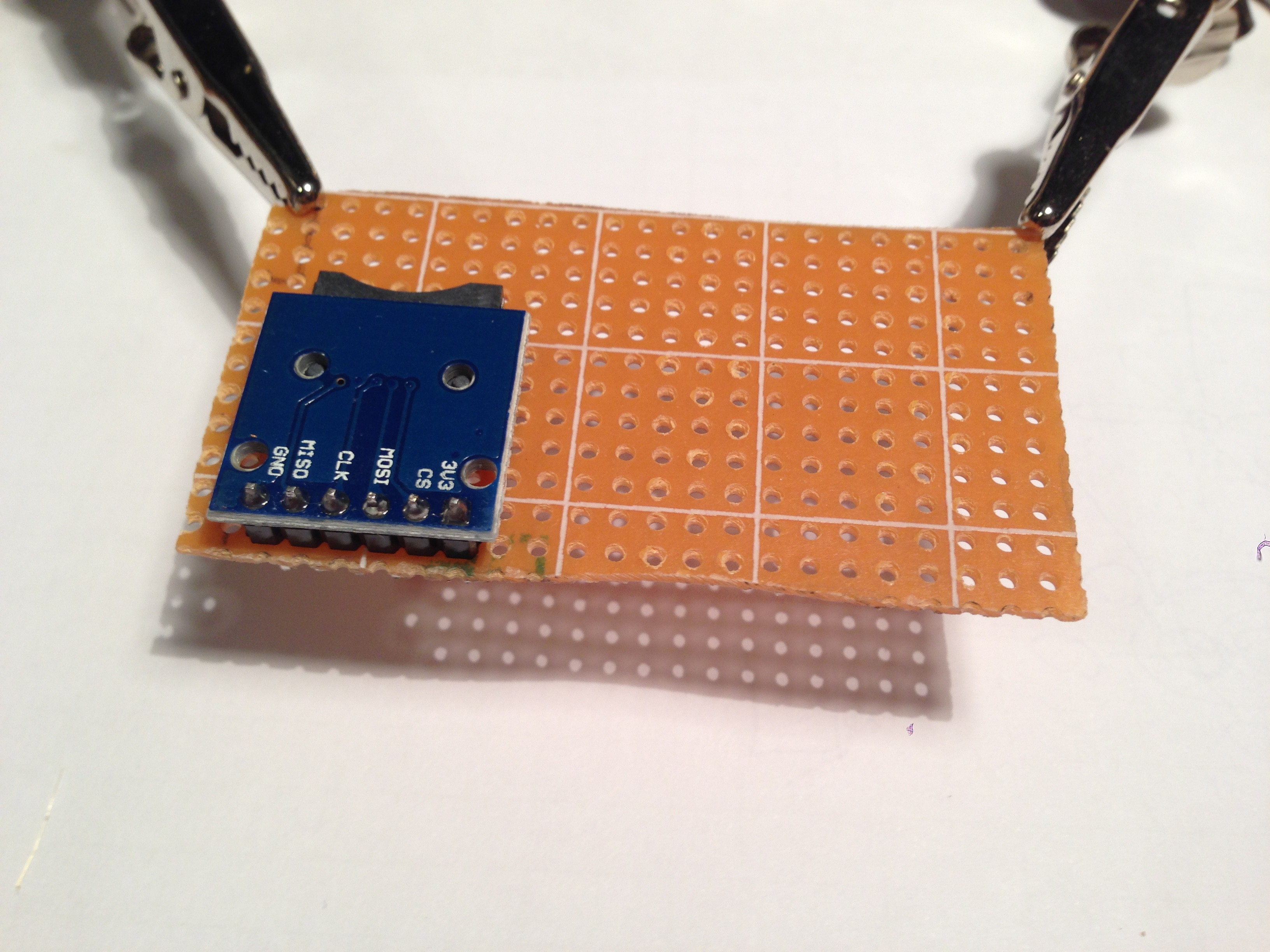
Solder the SD card reader, the wires are not on the board on the picture yet.
![]()
-
7Step 7
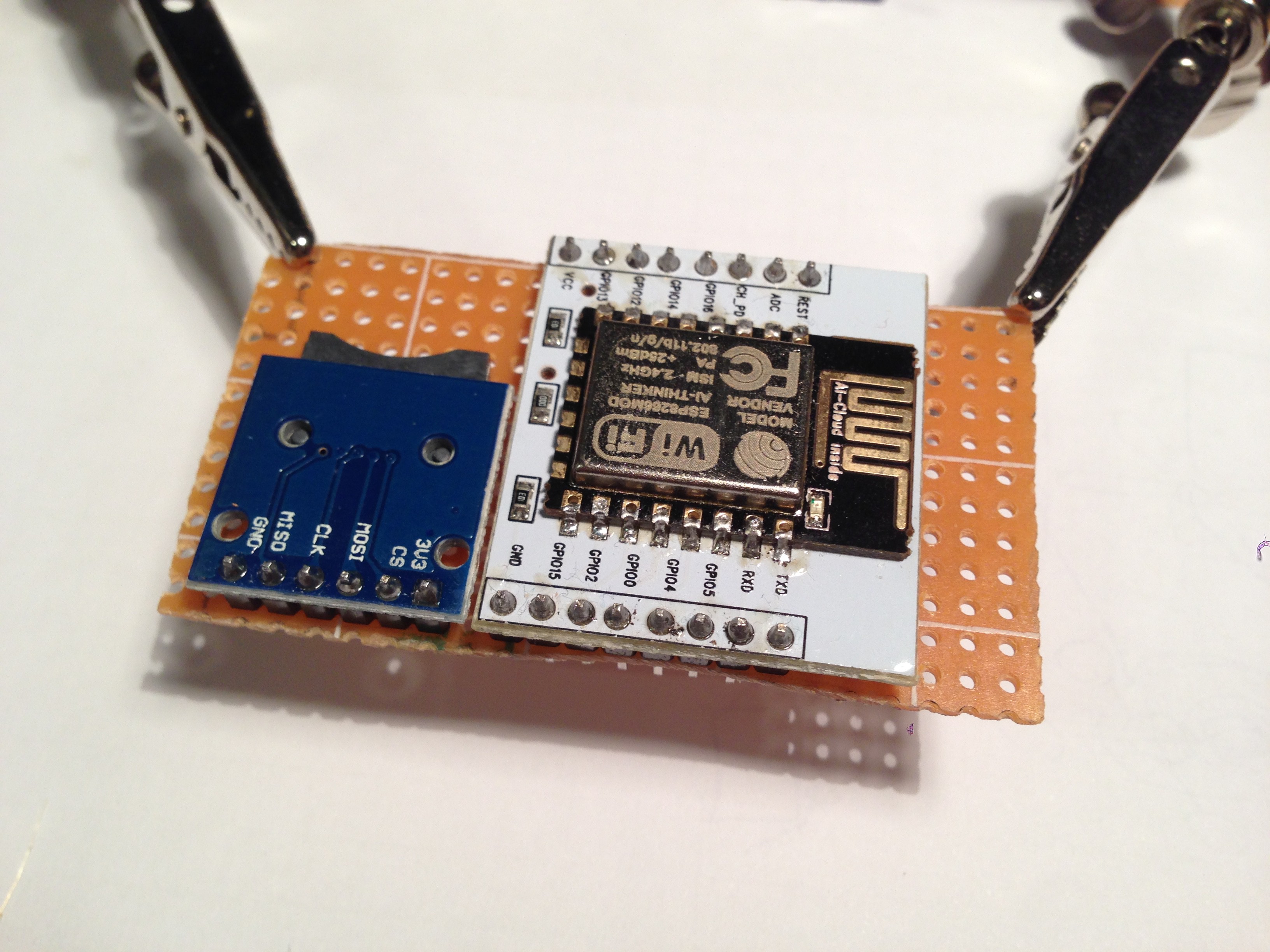
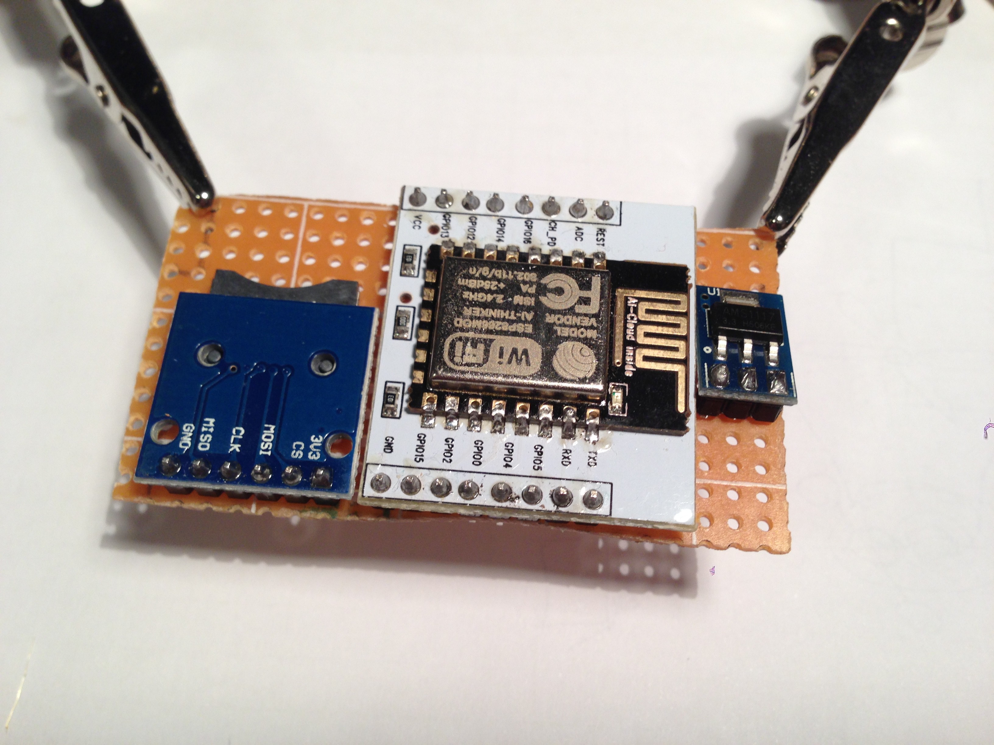
Solder the ESP on its breakout board.
![]()
-
8Step 8
Solder the USB cable.
![]()
-
9Step 9
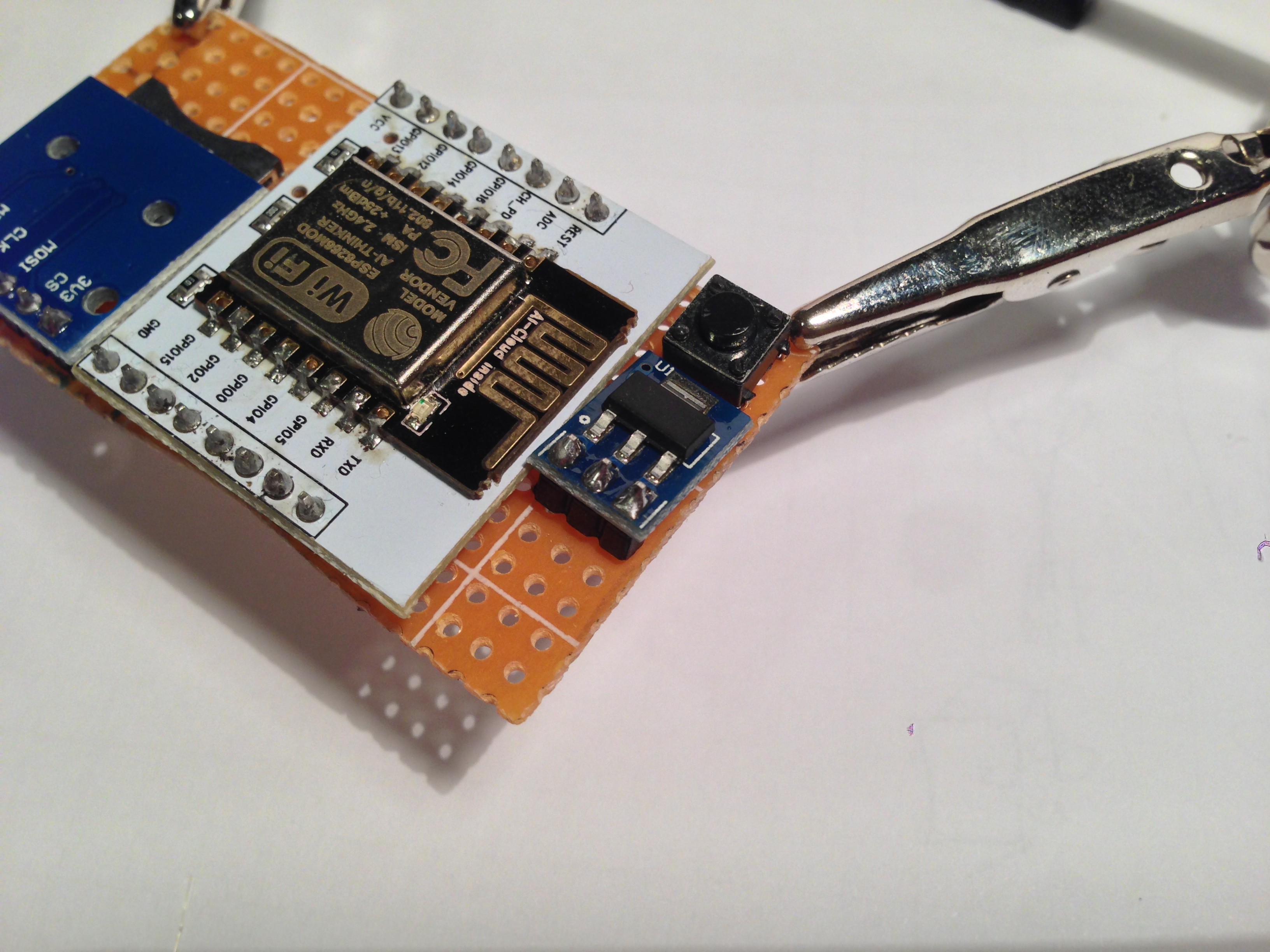
Solder the voltage regulator.
![]()
-
10Step 10
Solder the button.
![]()
Internet-of-Things Power Meter
Simple, cheap, easy to build and deploy, the IoT Power Meter provides accurate statistics on household power consumption.




Discussions
Become a Hackaday.io Member
Create an account to leave a comment. Already have an account? Log In.