-
1Step 1
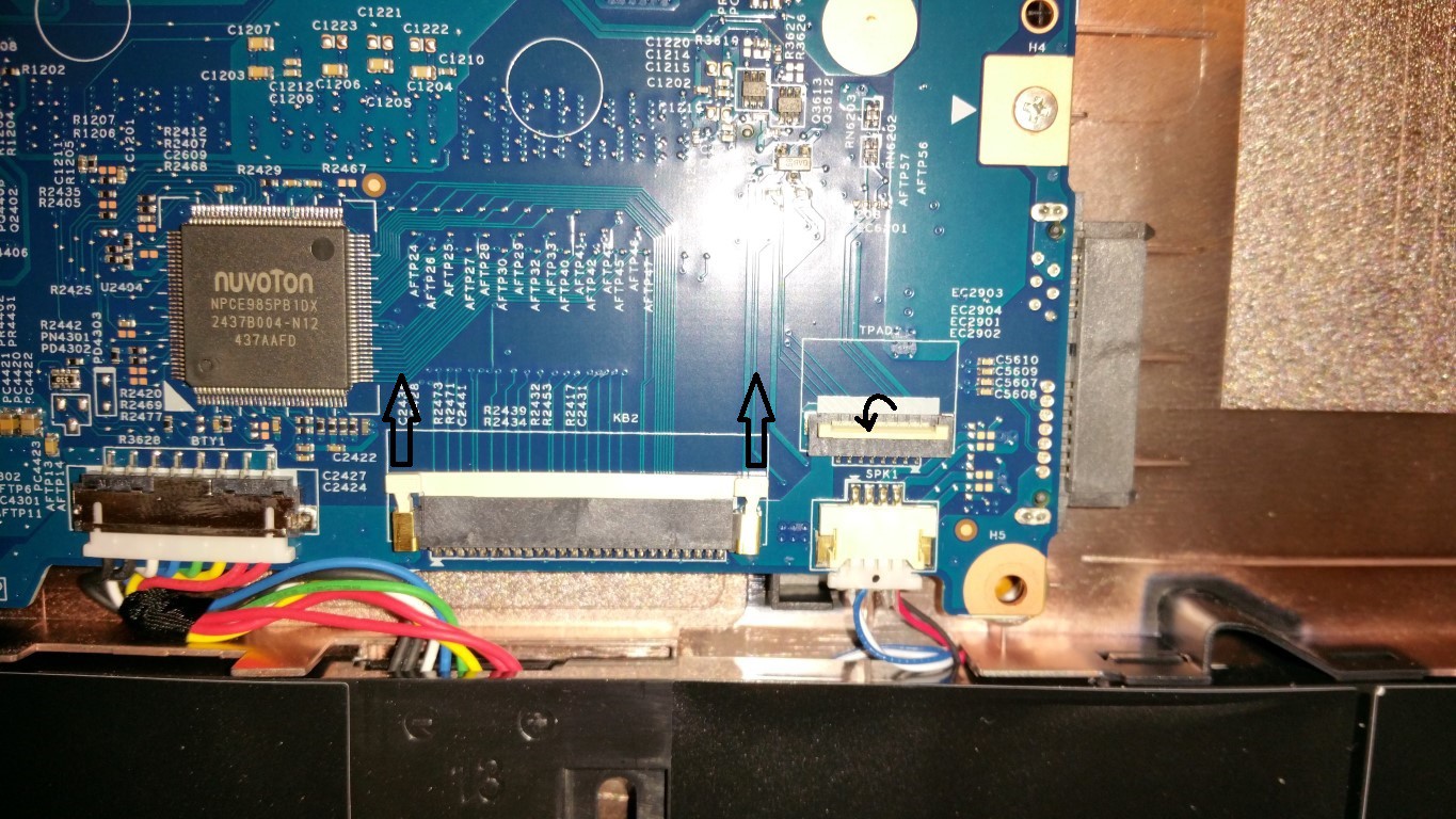
This video sort of shows some basics on opening up this laptop. Essentially you'll remove all screws from the bottom, then gently pop open the snap-clips around the perimeter of the top. Careful, the clips are delicate, screws are small, and 2 ribbon cables are still attached. Gently lift up just enough to get to the two ribbon cables connected to the motherboard. Detach them by opening each connector as shown with arrows below (small one flips up):
![]()
-
2Step 2
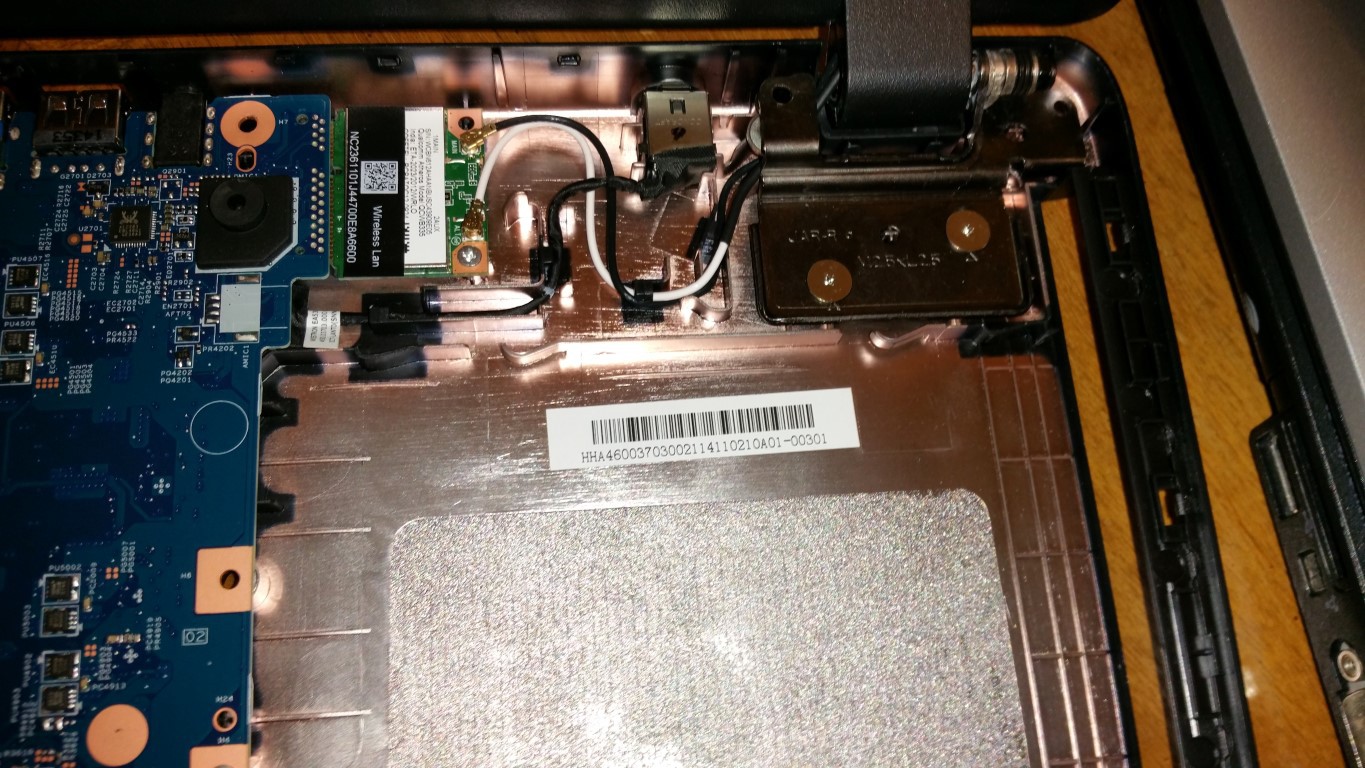
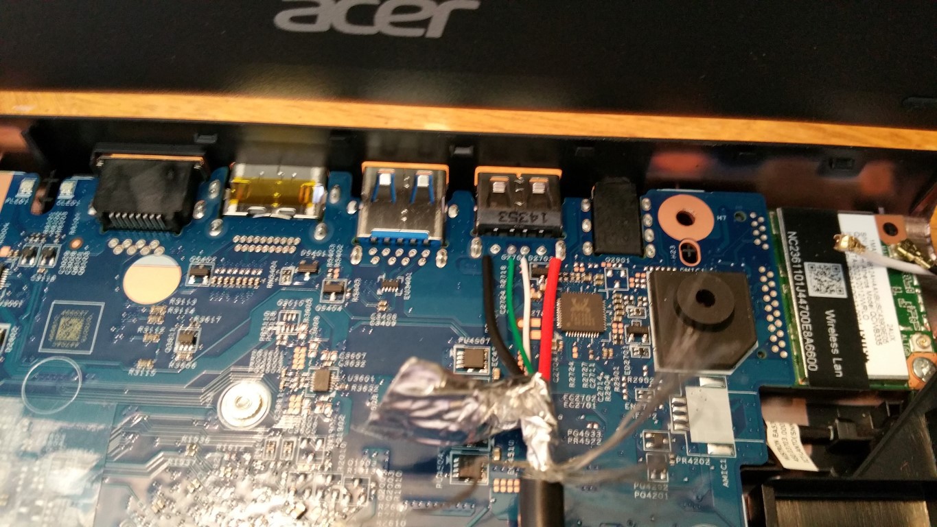
The ACER Aspire ES1-512-C12D Laptop has is a good amount of open space between the WiFi card and the charger port and the area where the optical drive blank goes is right inline with it. BONUS!
![]()
-
3Step 3
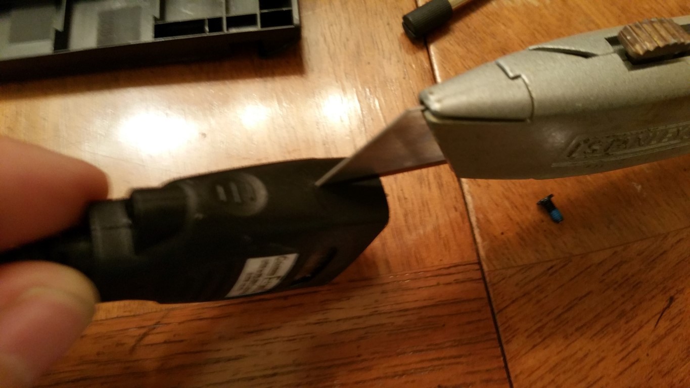
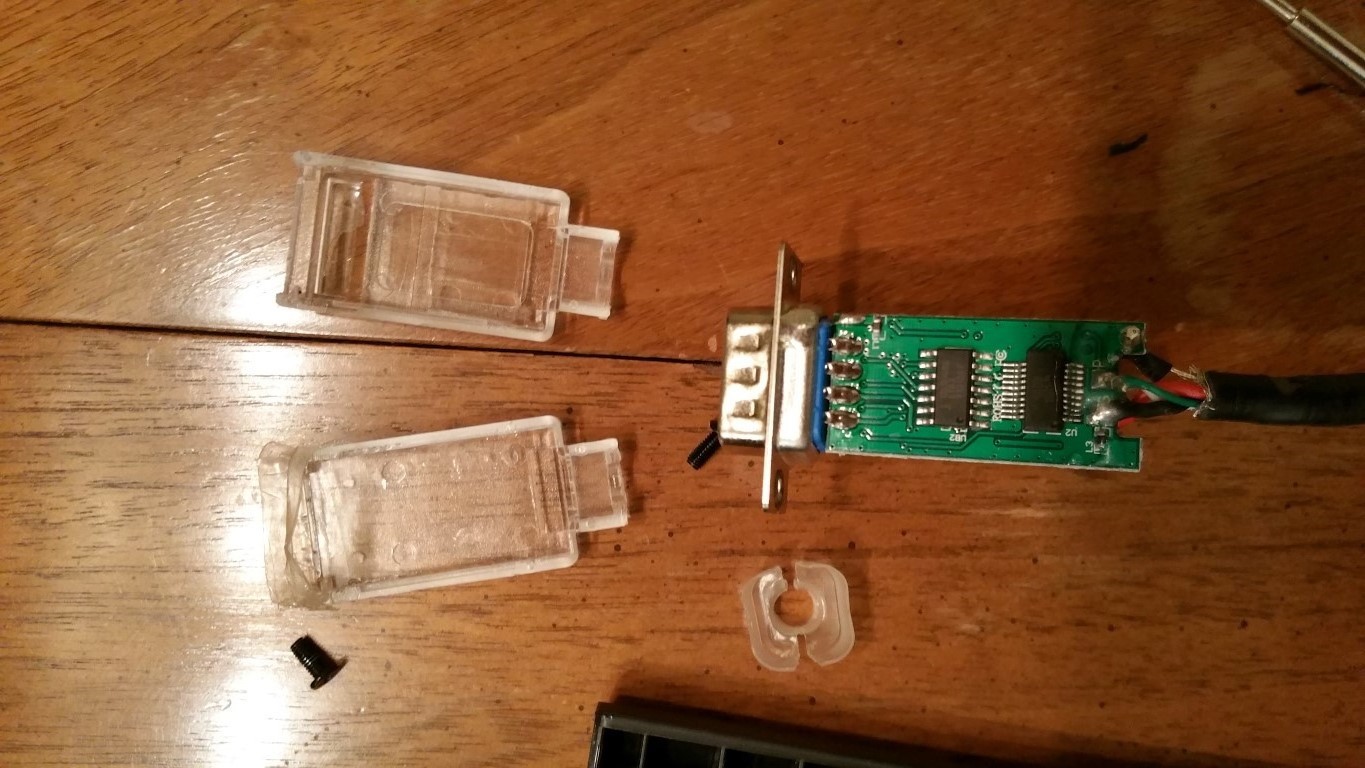
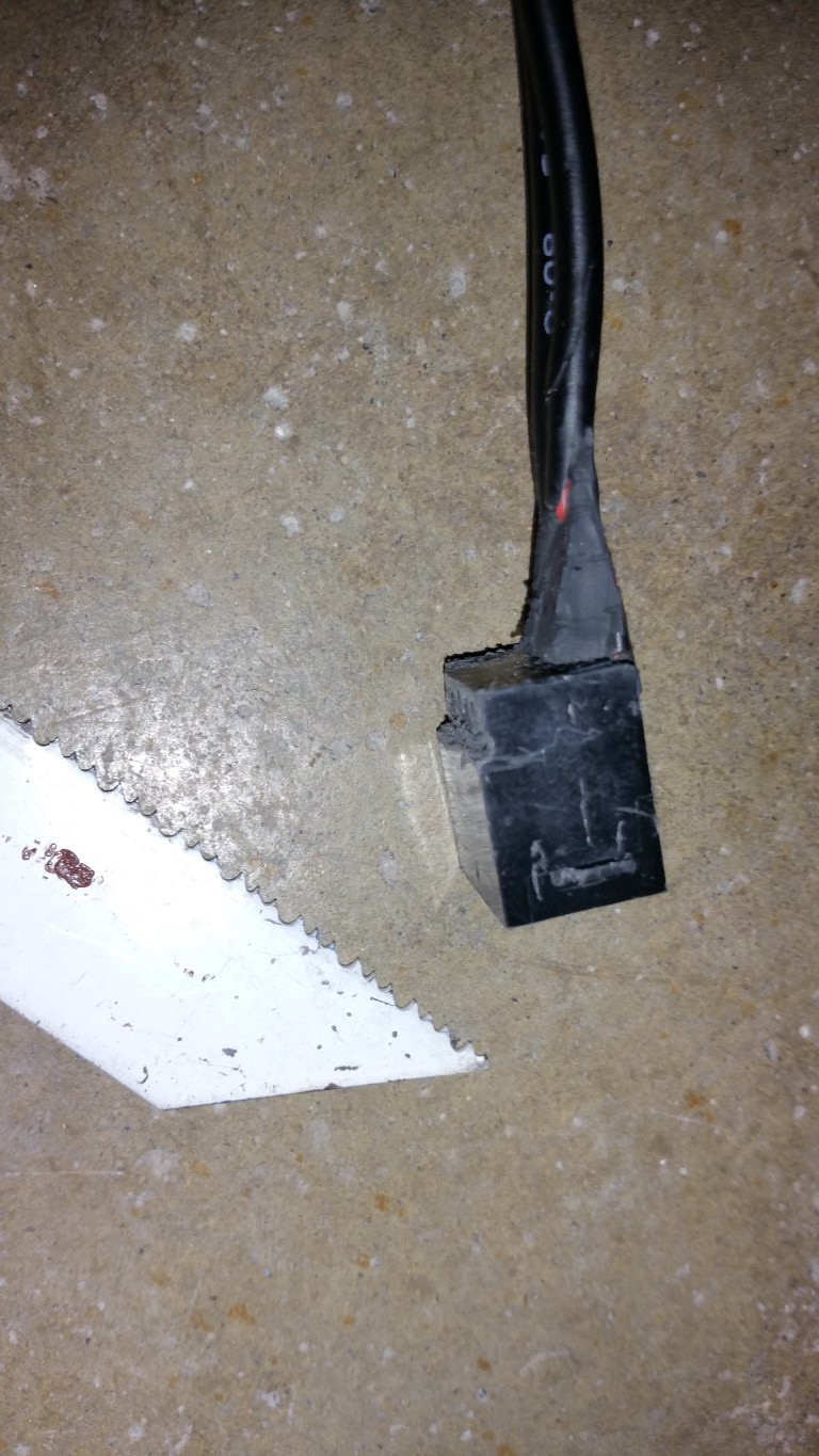
Begin by removing the RS485 adapter's over-mold. They typically some off relatively easy if you can start the cut right on the seam. There isn't any glue used on the inside and there is clear plastic clam-shell hood protecting the circuit board, but still you should be careful. Of course you can start with a different, bare RS485 converter board, but I used this $35 USB one from CommFront.
![]()
![]()
-
4Step 4
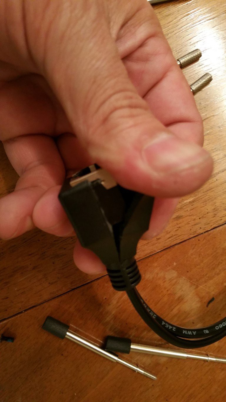
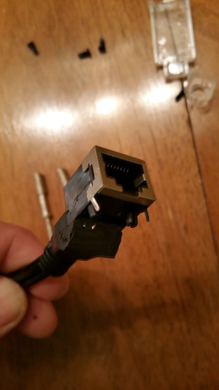
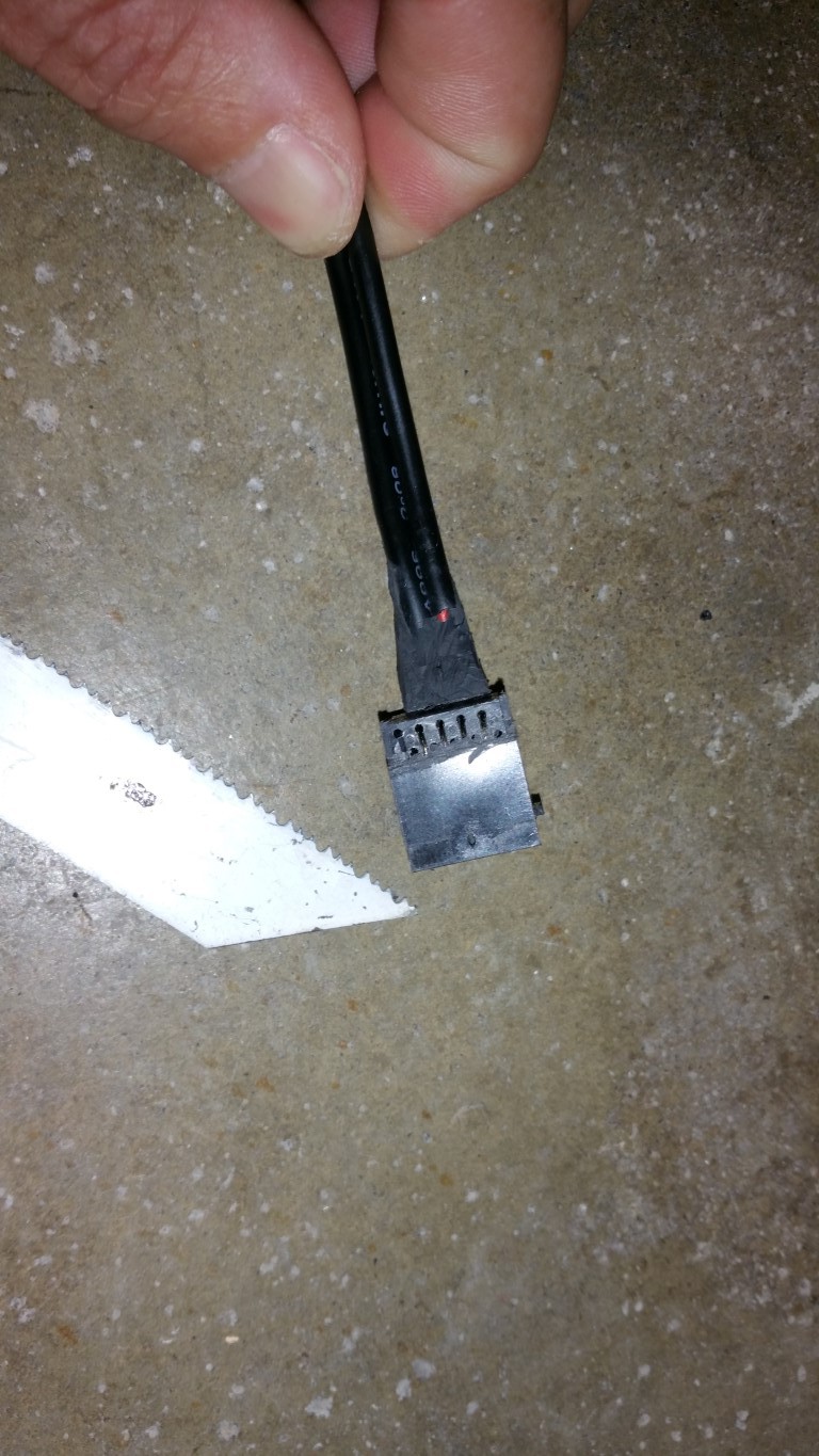
I limited my choice of parts to what I had on-hand since this project began late one night. The RJ45 port of the DB9 to RJ45 adapter I had was too tall to be used, but I found a low profile RJ45 in a set of POE Injector cables used for IP Cams and it had handy wires attached! I just removed the over-mold, which was adhered to where the wires solder to the pins, so I was careful to not damage the contacts and to nibble away at the remaining plastic.
![]()
![]()
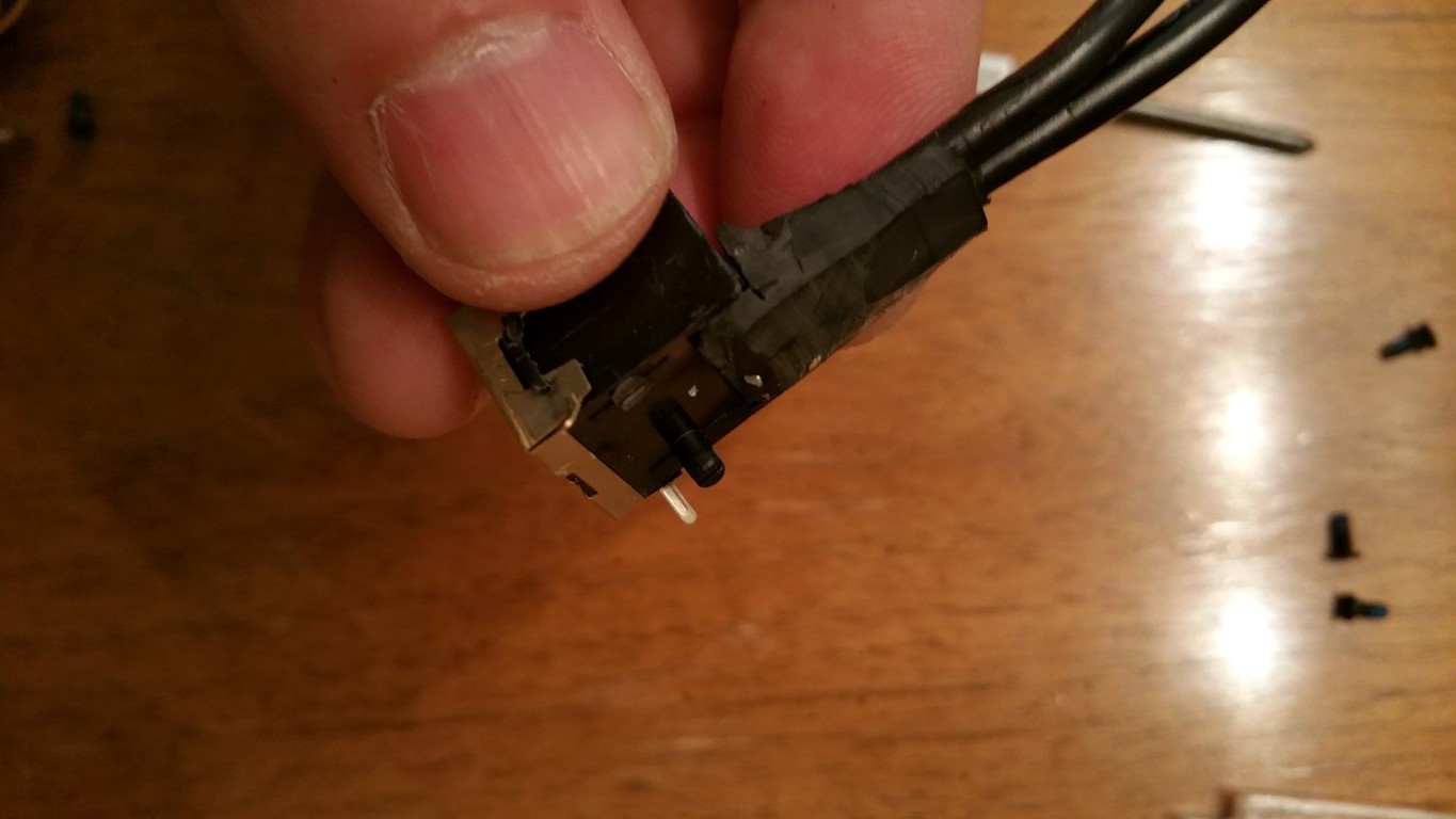
You can see the plastic hump in the picture above, this has to be removed as shown below, but there were wires molded into that plastic. So with careful shaving, I whittled it down, and also removed any mounting pins and then the metal reinforcement trim just fell off.
![]()
I figured the total height of the low-profile RJ45 socket was still too tall. So allowing the RJ45 socket to drop through the bottom of the laptop case a little bit gave me just enough room in height. I just had to create a notch which would help hold it, keep it from falling out the bottom. it wasn't much of a notch since there are RJ45 pins inside there, so be careful, go slow, but it was enough to lock it in. From the inside, it kind of wedges between the back wall of the laptop case and the notch.
![]()
![]()
-
5Step 5
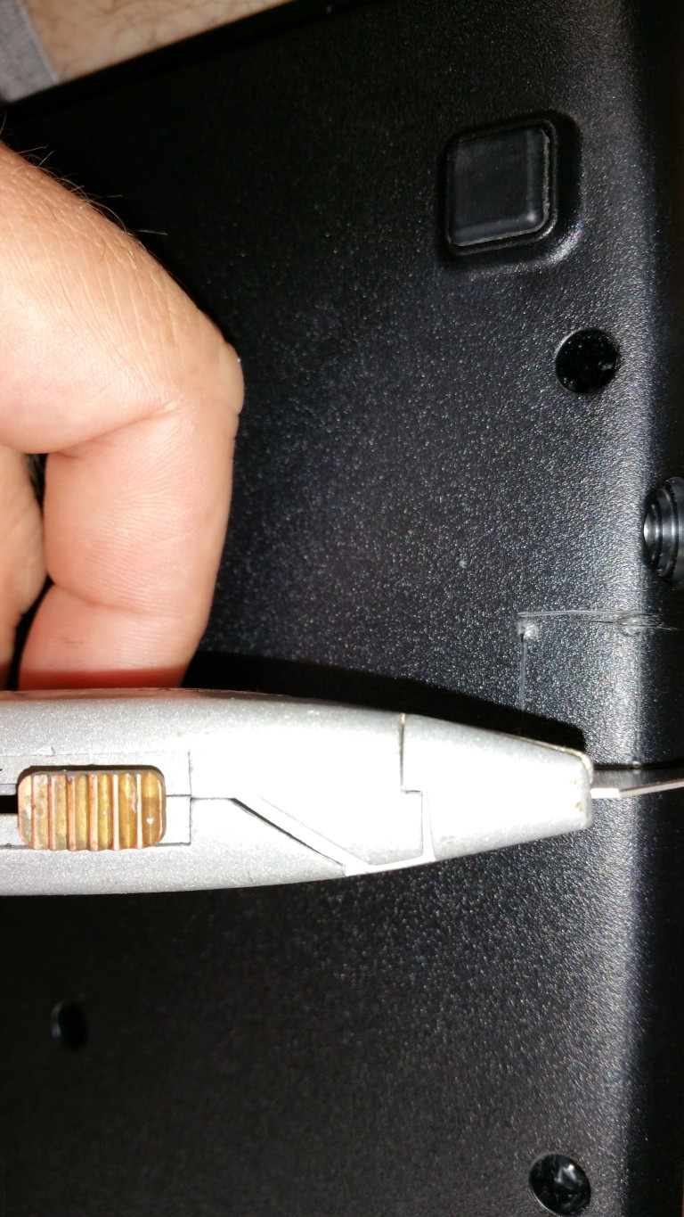
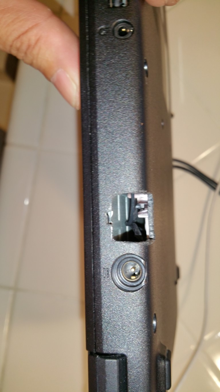
Next, was to cut the hole into the bottom case and back wall of the laptop. I put the RJ45 connector in place and scribed its edges into the Laptop case. Then I used an ice pick (drill would've been better) to push through to mark the outside of the case. Then it was a lot of careful work with the razor knife (Dremel would've been better) to cut out the hole, while being conservative on what is removed and checking along the way.
![]()
![]()
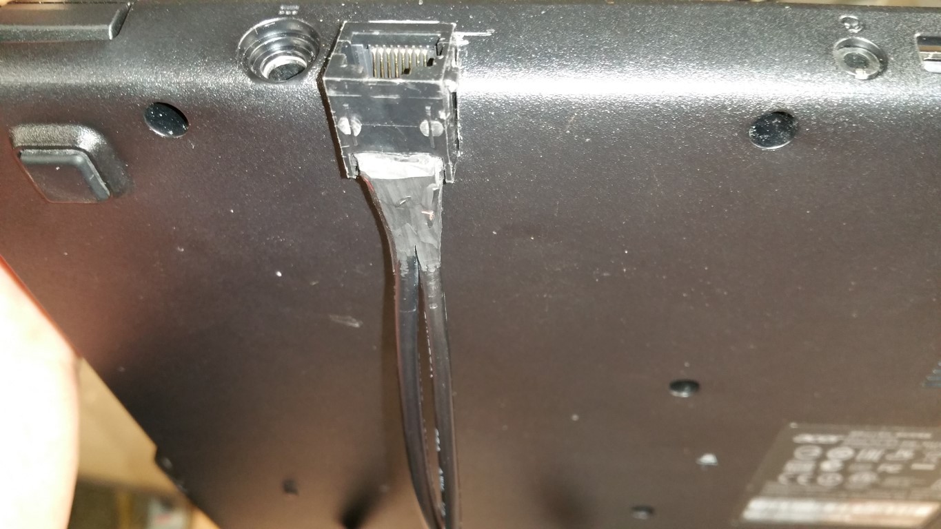
You can see in the picture above that I have the RJ45 port inverted, just to test fit the hole. The RJ45 "tab" slot will face up, as you can see in the picture below. The RJ-45 socket will sit behind the back wall of the Laptop and sit into the thickness of the case bottom, without protruding.
![]()
-
6Step 6
More steps to come, next stages involve Soldering components together and to the mother board. Stay tuned.
![]()
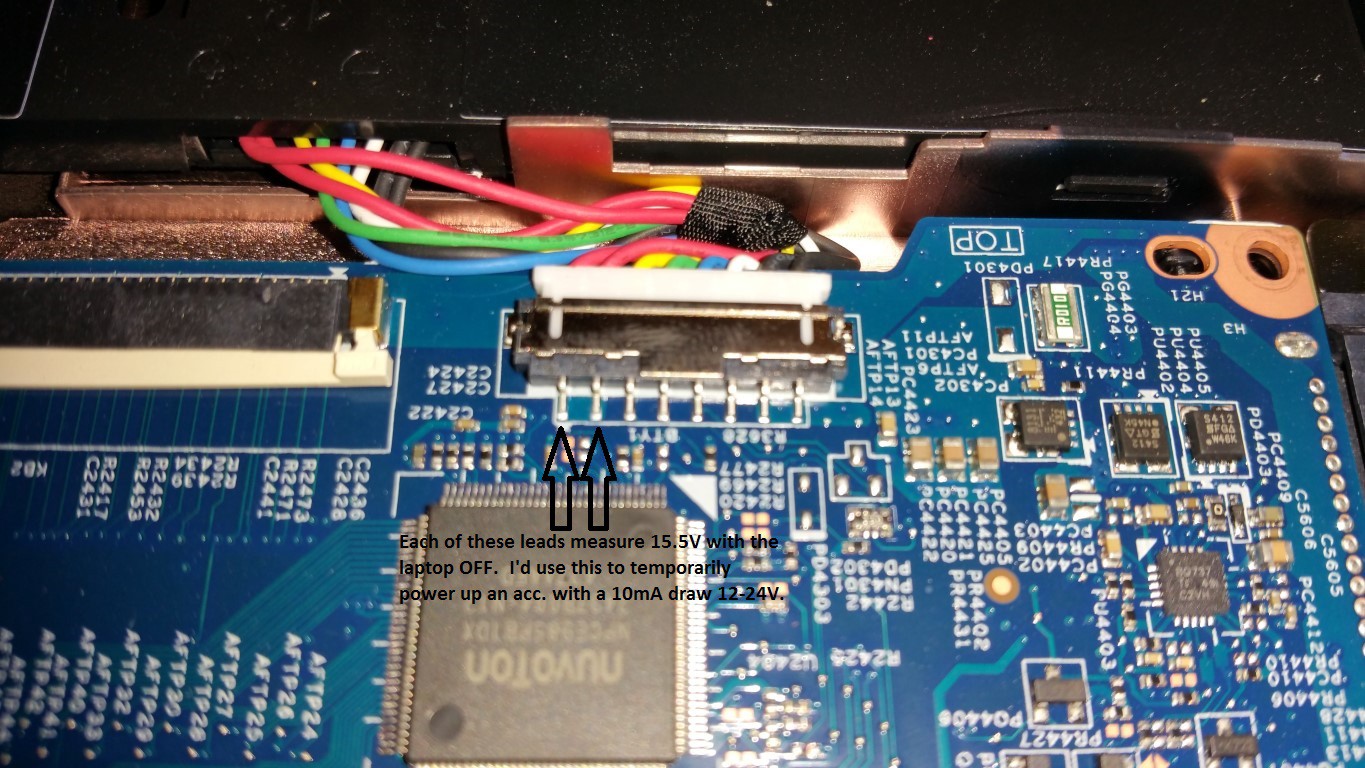
For the POE accessories, I'd need to power a small device that draws 10mA at 12-24V. If anyone has any thoughts or opinions on if it would be OK to tap into one of the 15.5V leads at the battery/charging circuit connection at the motherboard, (shown below) please let me know in comments.
![]()
Laptop with on-board POE RS485
For programming devices used in Home Automation I can plug in RS485 devices into the laptop and have them powered over the CAT5.
 controlmypad
Discussions
Become a Hackaday.io Member
Create an account to leave a comment. Already have an account? Log In.