 Thomas Flayols
This time I used the new design allowing to aligne the tubes. I took a piece of wood found on the beach. I 3D printed a back enclosure to protect the electronic.
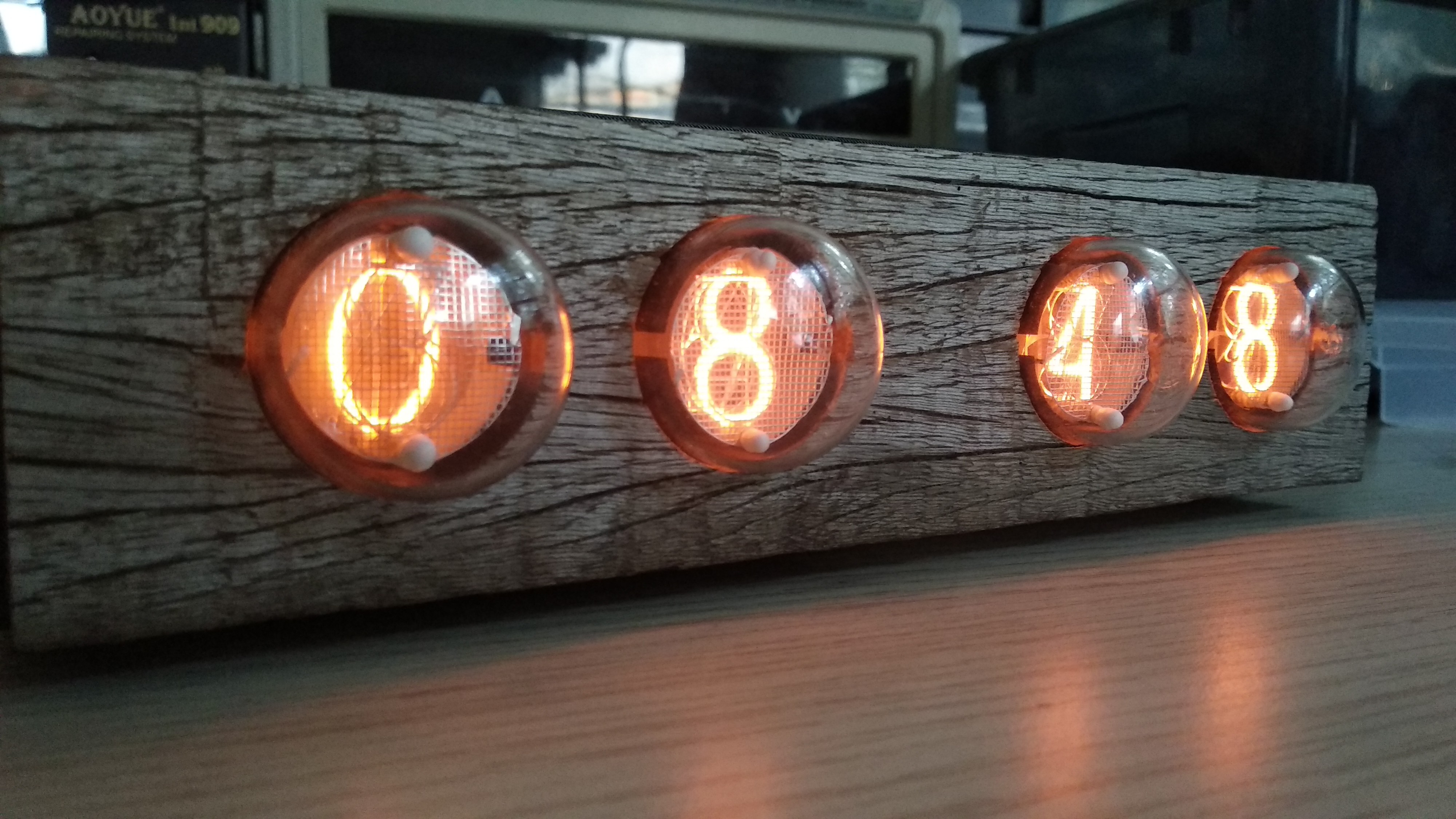
I like the mix of gray wood and warm red tubes !
While testing this clock I found some problem with the power supply module.
First, now the display module are powered in 3.3v. No problem for the Atmegas.. except that their internal RC oscillators are calibrated at 5V. At 3.3V the incoming uart messages are misread and the whole module is unusable, displaying random numbers.
I manage to recalibrate them, and that problem has been solved. I will go into the details in a next log.
The second problem is with the 170V switching power supply. It is not efficient enough, and the transistor get really hot after some time in the enclosure when powering 4 tubes.
This is more problematic and need some investigation. I took somemeasument and I found out that the gate voltage was oscillating a lot..
To finish this clock in time for a gift, I use the eBay Nixie power module I used in the first clock.
Discussions
Become a Hackaday.io Member
Create an account to leave a comment. Already have an account? Log In.
Beautiful, I have similar nixies and will definitely look into some old looking wood beams for an enclosure.
How did you make the holes for the tubes, and inner space for the electronics ? CNC ?
Thank you for the inspiration.
Are you sure? yes | no
Thanks !
Since I don't have a CNC, I used a 30mm forstner bit to drill the holes from the front side, and on the back I used a manual router to make some room for the bigger part of the tubes. The electronic is outside the wood, that why I 3d printed the rest of the enclosure.
Are you sure? yes | no
Ah thanks, I didn't see the enclosure on the picture I thought it was a square section wood beam.
Are you sure? yes | no
wow!
Are you sure? yes | no
Your right, the wood and tube color gives a very warm effect. Well done :-)
Are you sure? yes | no
Uh ... If you are getting scrambled UART messages due to a different voltage, that's not "calibration". Depending on UART speed you can easily survive a few percentages of tolerance, and the crystals aren't that sensitive.
I'd look at what speed you are running them on, because the ATMega's CPU speed is limited to about ... Five-ish MHz?
The internal oscillator shouldn't be used at that speed any more.
Are you sure? yes | no
In fact, the frequency of the internal oscillator depends on VCC. At 3.3V a factory calibrated oscillator for 5V-8MHz only oscillates at 7.4MHz (Figure 0-39 https://www.mouser.com/datasheet/2/268/Atmel-2486-8-bit-AVR-microcontroller-ATmega8_L_dat-1315266.pdf).
This gives an error of 7.5% and can easely explain the scrambled UART messages.
Note that in this design, I do not use external crystal.
Are you sure? yes | no
my favorite nixies and reclaimed wood, really nice!
Are you sure? yes | no