Thomas Flayols
-
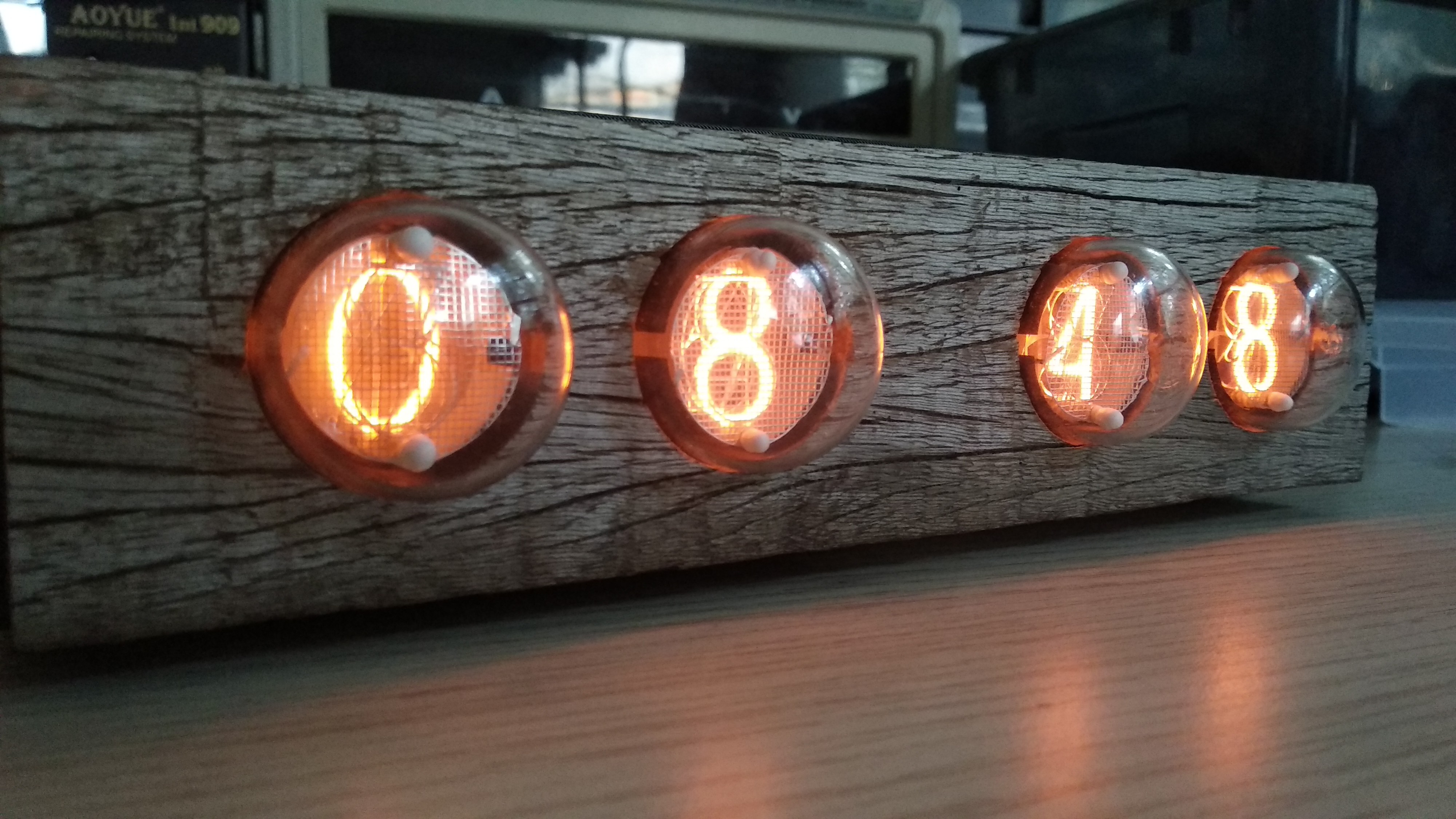
Another clock !
09/20/2018 at 18:54 • 8 comments![]()
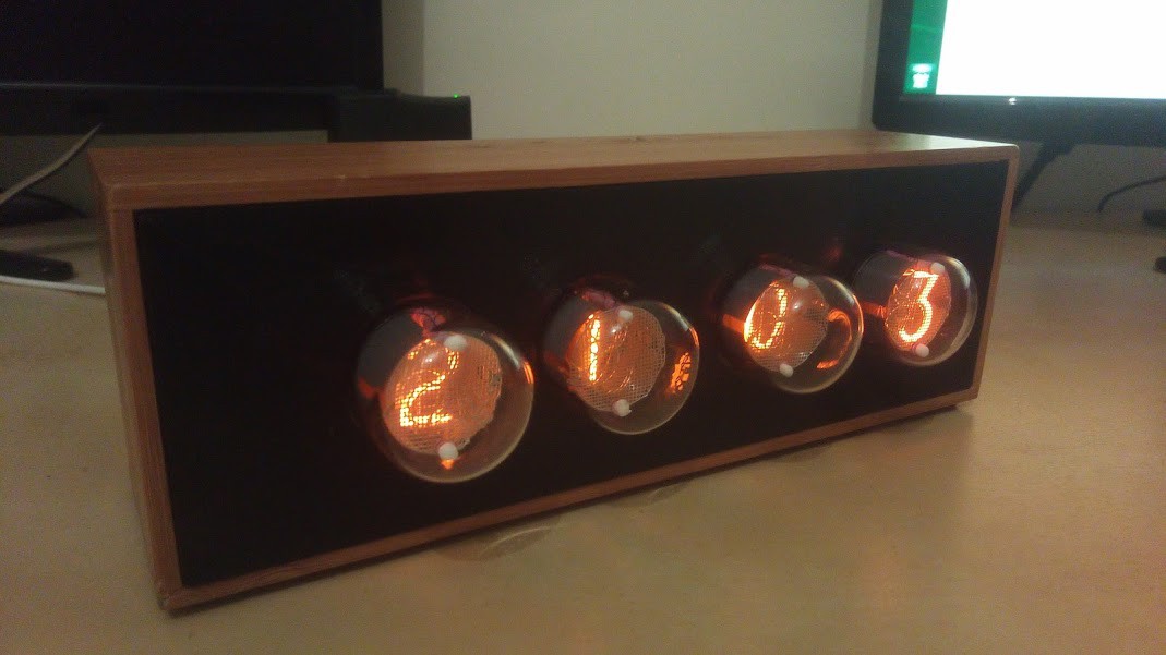
This time I used the new design allowing to aligne the tubes. I took a piece of wood found on the beach. I 3D printed a back enclosure to protect the electronic.
![]()
I like the mix of gray wood and warm red tubes !
While testing this clock I found some problem with the power supply module.
First, now the display module are powered in 3.3v. No problem for the Atmegas.. except that their internal RC oscillators are calibrated at 5V. At 3.3V the incoming uart messages are misread and the whole module is unusable, displaying random numbers.
I manage to recalibrate them, and that problem has been solved. I will go into the details in a next log.
The second problem is with the 170V switching power supply. It is not efficient enough, and the transistor get really hot after some time in the enclosure when powering 4 tubes.
This is more problematic and need some investigation. I took somemeasument and I found out that the gate voltage was oscillating a lot..
To finish this clock in time for a gift, I use the eBay Nixie power module I used in the first clock.
-
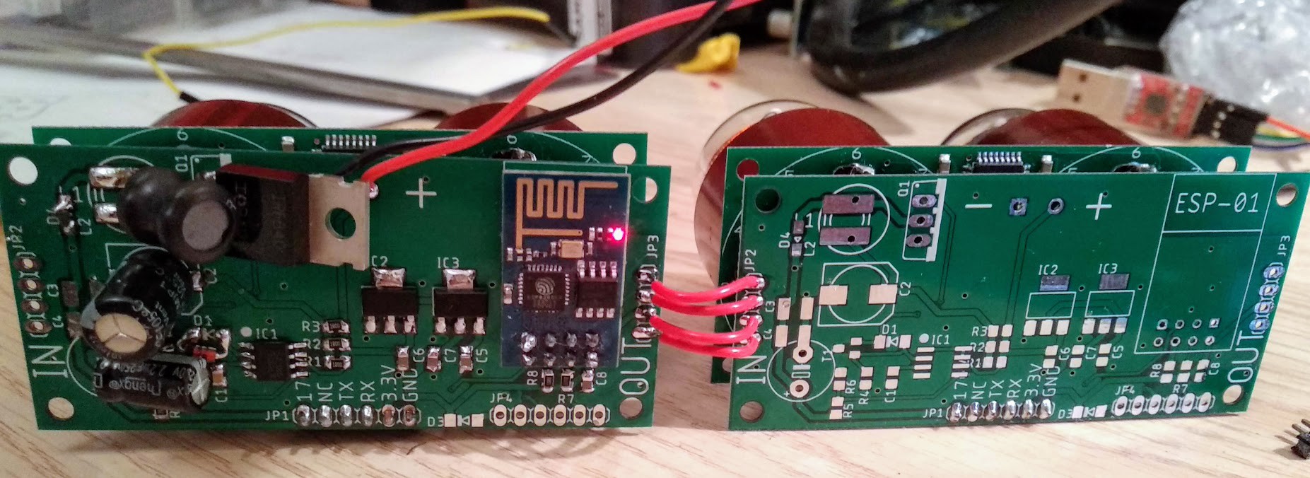
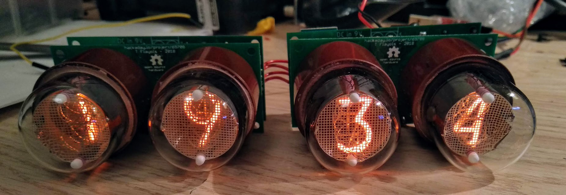
Everything works !
09/02/2018 at 18:01 • 0 commentsThe power supply and esp8266 board works as expected, it makes the wiring a lot easier !
![]()
![]()
I'm now looking for cool enclosures, I might give the concrete case another try.. I also would like to find an old wood box.
Maybe I can also order a machined aluminum front panel to do something like the first clock without the plastic.
-
New PCB received !
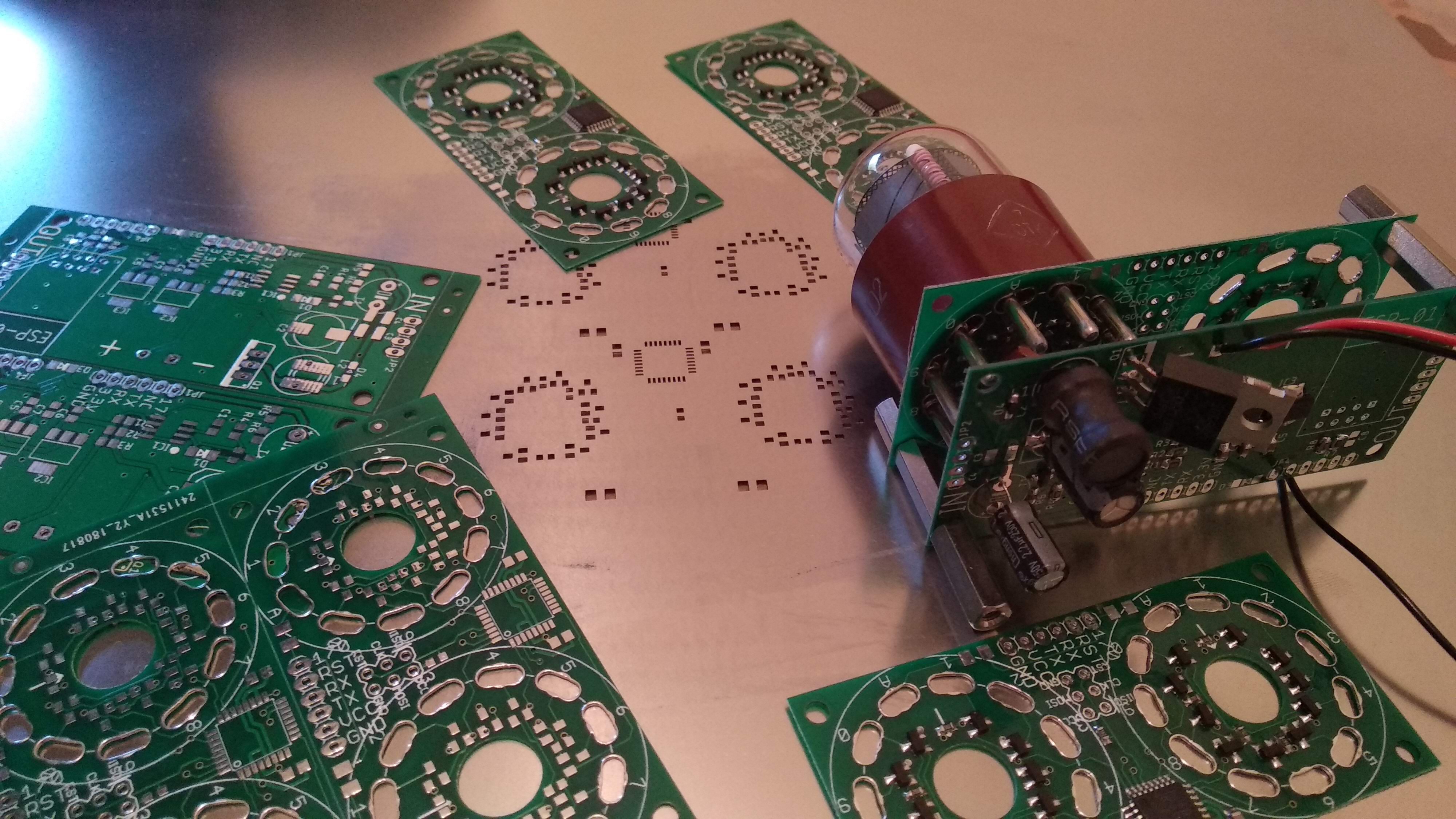
09/01/2018 at 22:19 • 0 commentsI just received my order from JLCPCB, this time I ordered solder paste stencil.
It's the first time I use stencil, and I have to say it's a game changing! So much quicker and cleaner than with the iron!
![]()
I'm missing some component for the ESP+power board, so I still have to wait a bit to validate the design.
Here is a video of my very first hot gun soldering process
-
ESP8266 firmware + PCB ordering
08/17/2018 at 08:43 • 0 commentsAfter a long break, I finally got the time to work on this project again.
So this log is a quick update about the esp8266 firmware used to drive the clock presented in the last couple of posts.
The ESP8266 is programed via the arduino SDK https://github.com/esp8266/Arduino
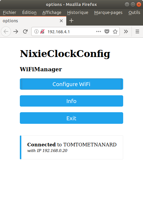
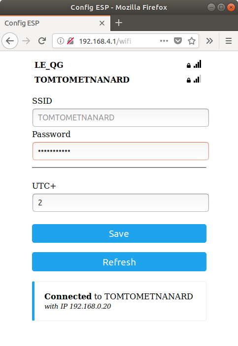
The firmware is really simple; it has to connect to a NTP server to get the time and send it to the daisy chained display modules via a serial port. The main complexity was to find a way for the user to enter his WiFi credentials.
I want the clock to be really minimalist from the outside, so no button used !
To setup the clock, I used the WiFiManager library here https://github.com/tzapu/WiFiManager. At startup an open WiFi access point is created. After connecting with a phone or a laptop, a connection popup ask for your home access point credentials and the UTC timezone used. This parameter are stored in flash and will be recalled at next bootup.
The firmware can be found in the GitHub repository here
![]()
![]()
There is room for additional feature, here are some ideas:
- Automatic summer time changes. I did not take the time to implement that and hopefully we soon get rid of summer time in Europe https://ec.europa.eu/info/consultations/2018-summertime-arrangements_en
- Parameter for a turn off time window to the clock to save tube's lifetime.
- Parameter to set animation style when changing numbers, or a dimming parameter (This needs the protocol and the display module firmware to be update)
- Act as something else than a clock, Facebook or YouTube likes counter ? Chronometer? Score display?
Some of the followers asked me to sell PCB with or without components. I'm still not sure about doing that, I have to see how much time soldering takes with the ordered solder mask, and to check the shipping cost...
Anyway, this project is opensource and openhardware!
I've just order a revision version that I talked about in the last post, and the esp8266+power supply auxiliary board. This design hasn't been tested yet so I would recommend to wait for the validation before ordering a PCB to a fab. I should get the boards in less than a month.
-
A concrete failure
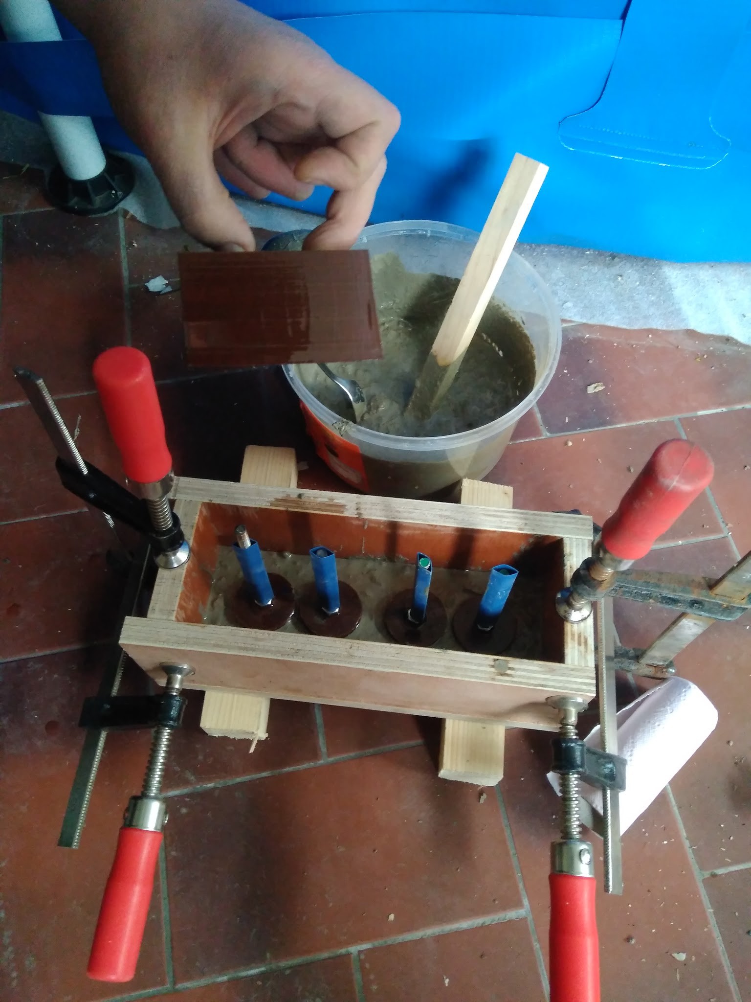
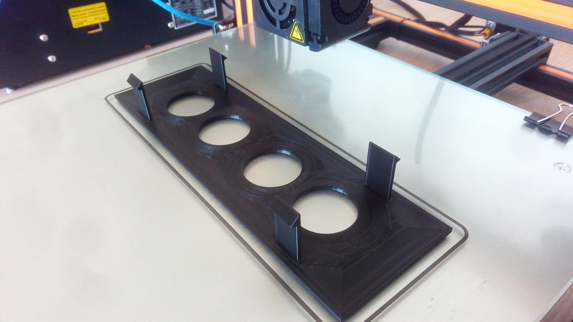
03/29/2018 at 16:35 • 0 commentsI wanted to try making a concrete clock with my modules.
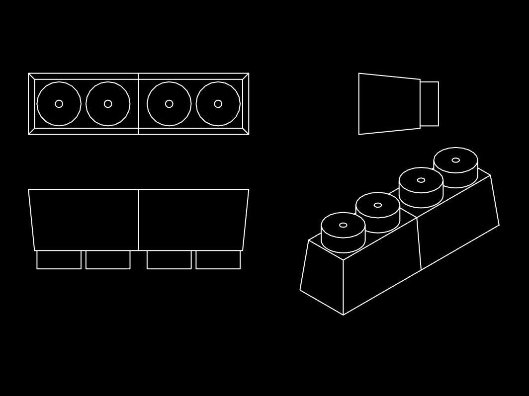
I started by designing an interior mold printed in 3d
![]()
The outside of the mold is made of wood panel.
![]()
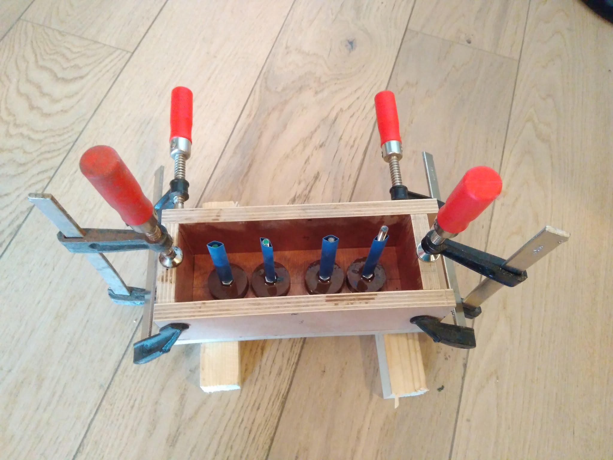
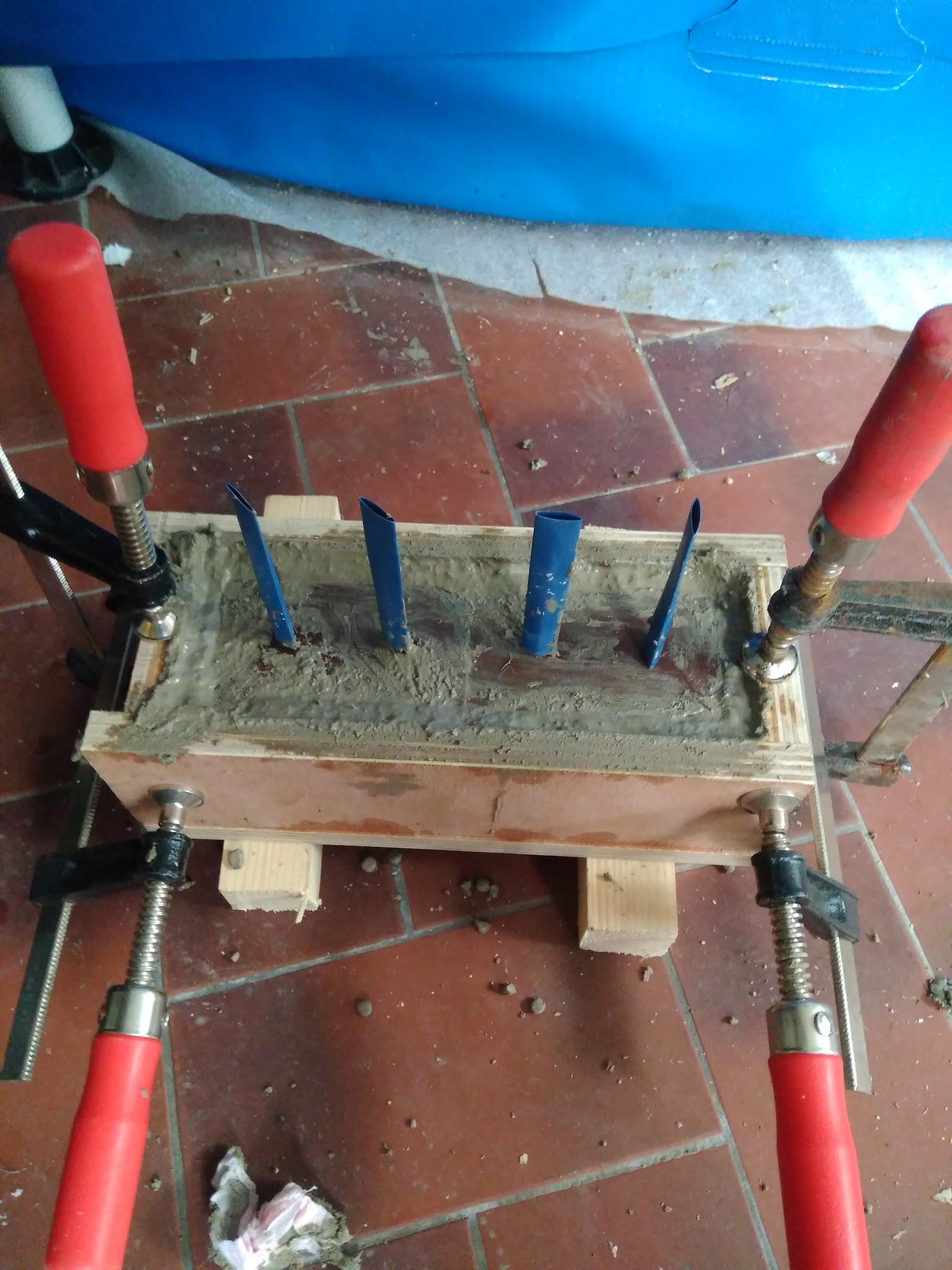
I poured the concrete in two stages.
![]()
![]()
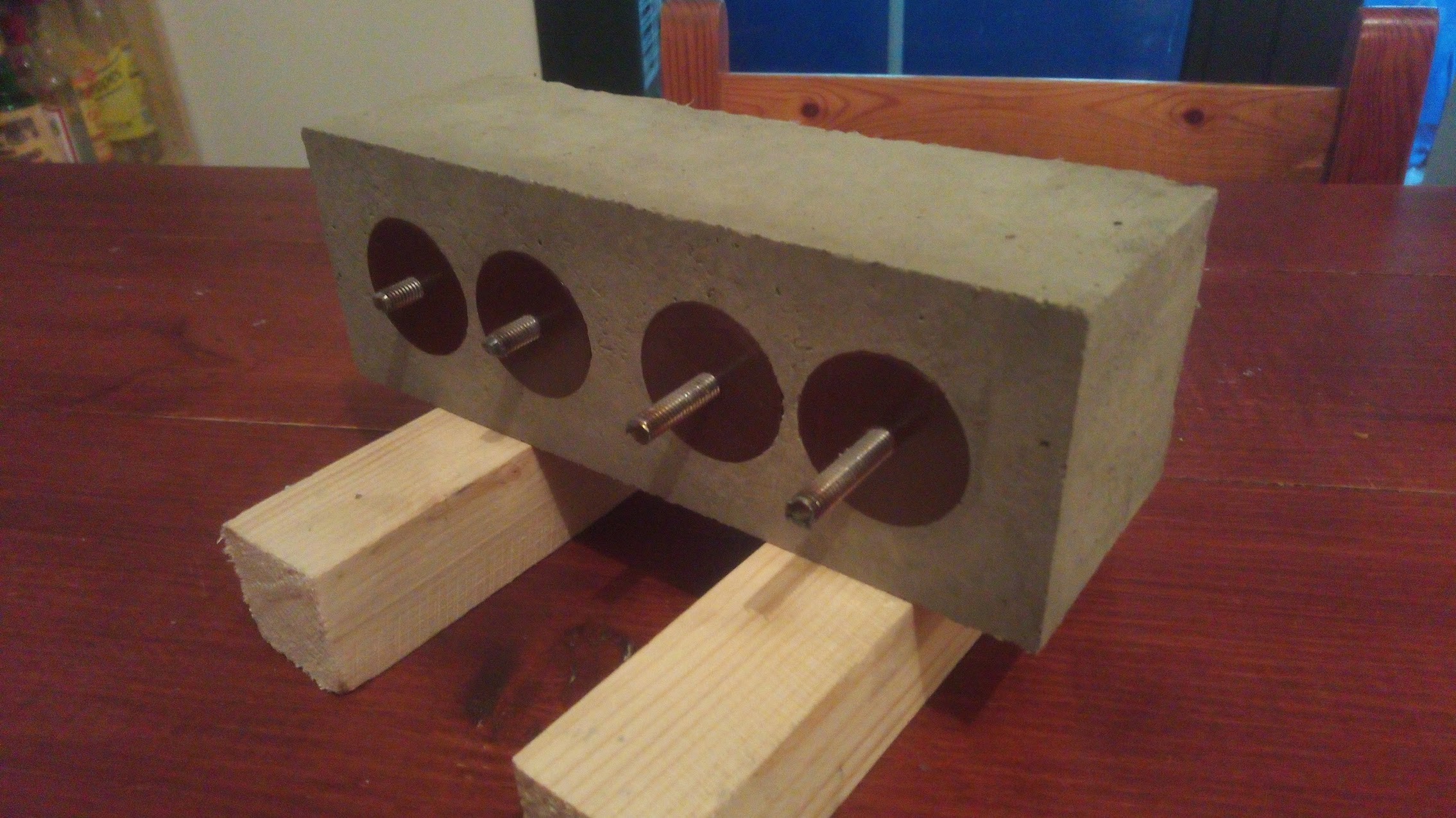
Everything seemed to be going well...
![]()
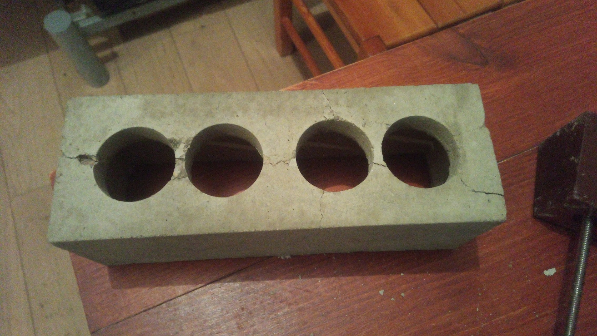
But removing the cylindrical parts was complicated. I had to bump them out. Result: big cracks!
![]()
I'm thinking of redesigning the cylinders to give them a conical shape. Maybe also add more fiber to the concrete...
-
Optional HAT: ESP8266 + Power Supply
03/15/2018 at 21:29 • 0 commentsThis optional board takes the same size and plugs behind the display module.
It makes wiring the daisy chain easier, and it can be populated with an ESP8266 master and/or a 170V and 3.3V power supply from a 9V input.
![]()
There is jumper on the back so that we can isolate the powers if several boards need to be populated with HV supply (in case we use a lot of nixies :-)
If no components are populated, the board simply acts as a wire. It could be considered a waist but making the wire is boring, and PCB manufacturing makes it for almost the price of cables and connectors... It also allows only HV caps to be filled and the power supply to be filtered locally.
![]()
HV DC
For the high voltage power supply, I copied a commonly used design from :
https://threeneurons.wordpress.com/nixie-power-supply/
![]()
It does not have a perfect efficiency but it is simple and cheap.
For 3.3V, the simplest and cheapest solution I have found is two linear regulators in series. A 5v and a 3.3V. This limits the input voltage to 9V.
-
Rev 1
03/10/2018 at 16:34 • 0 comments![]()
So here is a revision of the PCB, It addresses two major problems of the first design.
The anode resistances were 0402 sized, too small to dissipate a power of (P=RI² = 22k*2.5mA² = 0.14 W) They are replaced by 1206 (0.25W).
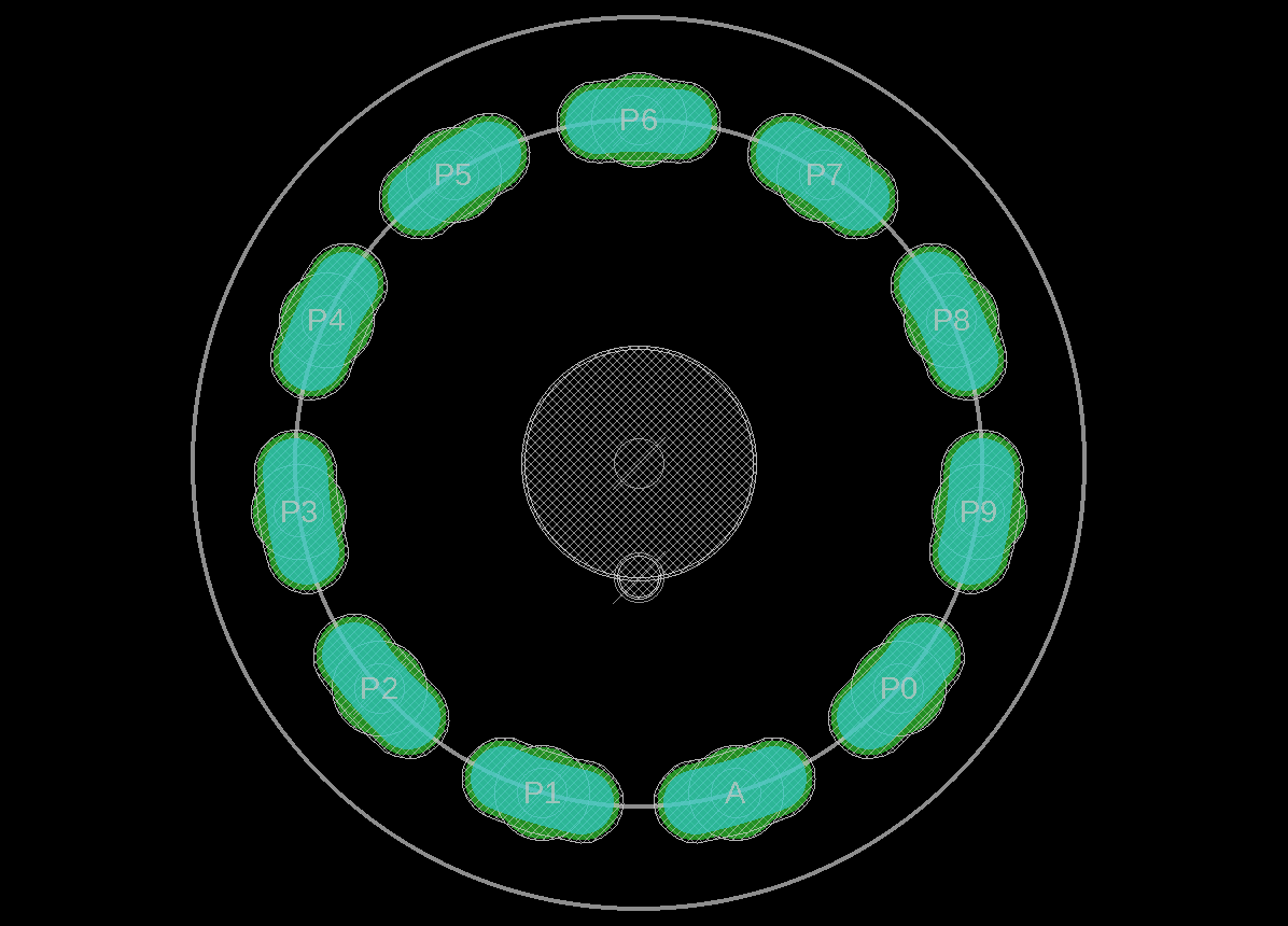
Second issue, some IN1 nixies have very bad alignments between numbers and pins. For example from another project here :
![]()
[bad alignment effect from an other HAD project] In order to compensate, I modified the tube footprint to have a little margin.
![]()
To do this with Eagle, I generated the commands from a python script:
# Script to do circular slots in eagle
from math import cos,sin,pi
arclen = 0.12 #rad
r=13.5 #mm
Nslots = 11
cmds = [";CHANGE LAYER 17 ;CHANGE WIDTH 3.0",
        ";CHANGE LAYER 29 ;CHANGE WIDTH 3.2",
        ";CHANGE LAYER 30 ;CHANGE WIDTH 3.2"]
for cmd in cmds:
    print cmd
    for i in range(Nslots):
        angle = i*2*pi/Nslots
        start_x = r*sin(angle-arclen)
        start_y = r*cos(angle-arclen)
        opp_x   =  -start_x
        opp_y   =  -start_y
        stop_x  = r*sin(angle+arclen)
        stop_y  = r*cos(angle+arclen)
        print ";ARC CW ({} {}) ({} {}) ({} {})".format(start_x,start_y,opp_x,opp_y,stop_x,stop_y)

#milling outline

# A1 ____ B1
#   (____)------
# A2 \  / B2    | r
#     \/ _ _ _ _|
width = 2.5
print " "
Nslots = 11
cmds = [";CHANGE LAYER 46 ;CHANGE WIDTH 0"]
for cmd in cmds:
    print cmd
    for i in range(Nslots):
        angle = i*2*pi/Nslots
        A1_x = (r+width/2.)*sin(angle-arclen)
        A1_y = (r+width/2.)*cos(angle-arclen)
        B1_x = (r+width/2.)*sin(angle+arclen)
        B1_y = (r+width/2.)*cos(angle+arclen)
        A2_x = (r-width/2.)*sin(angle-arclen)
        A2_y = (r-width/2.)*cos(angle-arclen)
        B2_x = (r-width/2.)*sin(angle+arclen)
        B2_y = (r-width/2.)*cos(angle+arclen)
        print ";WIRE ({} {}) @-{} ({} {});".format(A1_x,A1_y,r+width/2.,B1_x,B1_y) #from A1 to B1
        print ";WIRE ({} {}) @-{} ({} {});".format(A2_x,A2_y,r+width/2.,B2_x,B2_y) #from A2 to B2
        print ";WIRE ({} {}) +180 ({} {});".format(A1_x,A1_y,A2_x,A2_y) #from A1 to A2
        print ";WIRE ({} {}) -180 ({} {});".format(B1_x,B1_y,B2_x,B2_y) #from B1 to B2
Finally, a few small changes, I re-centered the ATmega8 to move it away from the tube pins. And all base resistors are changed from 0402 to 0603 for easier welding.
I'll push that to github after a triple check !Done! -
Let's make a clock with this!
03/05/2018 at 23:39 • 0 comments![]()
This is the kind of clock that motivated this module. Twice two digits for hours and minutes, a simple wooden box and a PLA panel.
For power supplies, we need 3.3v and 170v.
From a voltage of 9V, I use an LM317 plugged in to make 3.3v (I could have used a fixed regulator, but I didn't have any on hand)
For the 170V, I bought this.
[Left 3.3V - Right: 170V ] The master is a ESP8266-01. There's no buttons.
At the boot of the clock, a free wifi is created for 30seconds for the first configuration. If a user logs in, he can set the host SSID and password via a web page. He can also choose the timezone.
After 30 seconds, or after setting is done, the time is updated from the internet.
The box is a bamboo box sold for the bathroom!
Supports are 3d printed to hold each module in the box.
The front-panel is also 3d printed.
![]()
Low cost dual Nixie Driver
A simple board, driving 2 nixies from discrete transistors and an Atmega8.