 ben biles
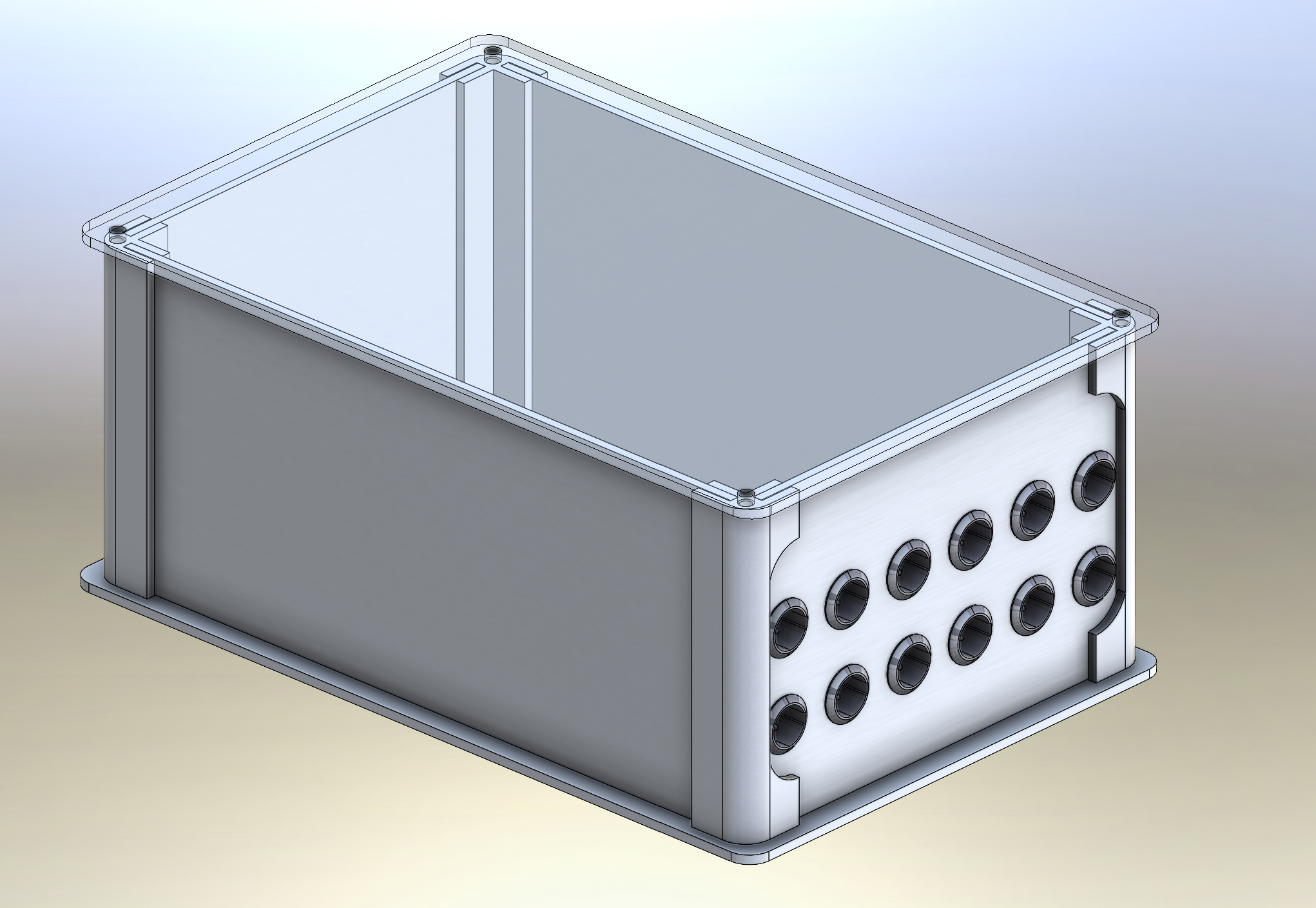
The corners allow the panels to be removed so I can 1st 3d print the panels with the connector holes in place to make sure the boards and connectors etc all fit.
after that I will use the plastic panels as templates and copy it to aluminium , drill cut etc.
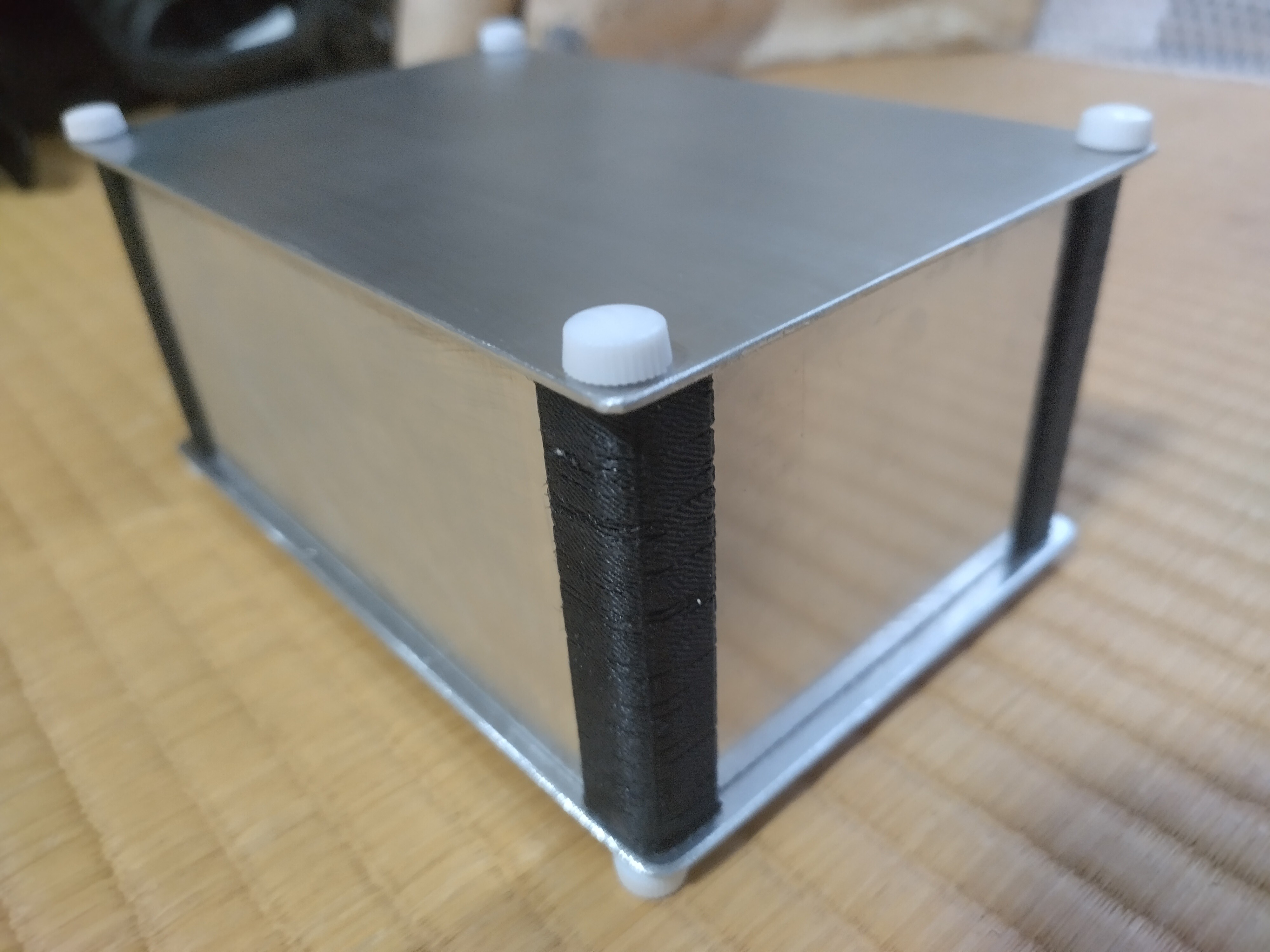
I will get the corner parts 3d printed in metal or CNC'd
The plastic bolt heads are only there for fast access while its still being programmed.
There is some flex in the 2 long side panels so I will need some more support there.
The 2 main digi and analogues pcbs sandwiched together fit exactly and they will have some kind of plastic mounting in between them both with bolts securing them in place through the long side panels. that maybe be enough rigidity to stop any flexing.
I also need to mount the OLED screen in the side panel near the power supply. its going to be tight !
Discussions
Become a Hackaday.io Member
Create an account to leave a comment. Already have an account? Log In.