-
Motor Attachments
08/15/2015 at 02:52 • 0 commentsMotors are generally useless when not attached to other components of a machine. However, unlike other components, motor shafts can't simply be glued or duct taped together. A solid connection is sometimes difficult to make, especially on a round, smooth shaft. While working on this project, we have tried duct tape, electrical tape, epoxy, and many other solutions to attach components to motors. We have found that these methods are unstable and fall apart quickly. We eventually resorted to buying parts online, and these have made the process much easier.
Most connections to stepper motor shafts rely on a metal cylinder surrounding a shaft with a small screw pushed in perpendicular to it. We bought an axle coupler to connect our round shaft to the square VEX drive shafts. We also have a universal mounting hub to connect our stepper with the rotating platform.
Servos usually come with a variety of plastic horns that lock onto the gear head and screw into place. Drilling through the horn allows screws and bolts to be connected to the servo and the component.
-
Code for the Adafruit Motor Shield V2
08/15/2015 at 02:26 • 0 commentsFor this particular project, we chose to use a motor shield to make the code simpler. In this case, we bought an Adafruit Motor Shield V2 for Arduino. Adafruit has created their own library to go with the motor shield. The library contains shortcuts for running servos, DC motors, and steppers. In addition, it is compatible with the AccelStepper library. The AccelStepper library is what we mainly use. It gives the user control of the stepper using position, velocity, and acceleration functions. Using the position function, we are able to write a mathematical equation to express the position we want the stepper at with respect to time. Using some calculus, we can extend this and make use of the velocity and acceleration functions if we wanted to.
More information on the Adafruit Motorshield kit.
More information on the AccelStepper library.
-
Motor Selection
08/15/2015 at 01:40 • 0 commentsWhen designing the SpiroBot, we had to choose which types of motors to use. Some of the more popular motor assemblies include DC motors, servos, and steppers.
DC motors are the most basic, but spin at extremely high speeds. Because of this, they often require complex gearing systems to bring the speed down. Since we didn't want to mess with too many gears, we ruled DC motors out.
Stepper motors are rather difficult to drive. Unlike simple DC motors, steppers require a motor controller to power several magnetic coils in a specific order to move. However, steppers offer extremely high accuracy and substantial torque. Because of this, we chose to use a stepper to drive the pen holding mechanism. In order to make a stepper more straightforward to run, we also chose to use a motor shield as the motor controller to make the code simpler.
Servos are extremely easy to control, especially when you have a motor shield and additional libraries in the Arduino code. Because of this, we are using a 180-degree servo to control the vertical motion of the pen. We also initially chose to use a continuous servo on the bottom of the machine to rotate our platform. However, we found that the accuracy of this motor varied wildly, causing uneven spacing in patterns drawn and making repeating patterns nearly impossible, even with the same code. We are now in the process of changing the bottom platform-rotating motor to a (hopefully) more accurate stepper. The function of moving the pen, however, does not require extremely high accuracy, so we are continuing to use a servo for that.
For more information on motor selection, take a look at Adafruit's Motor Selection Guide.
-
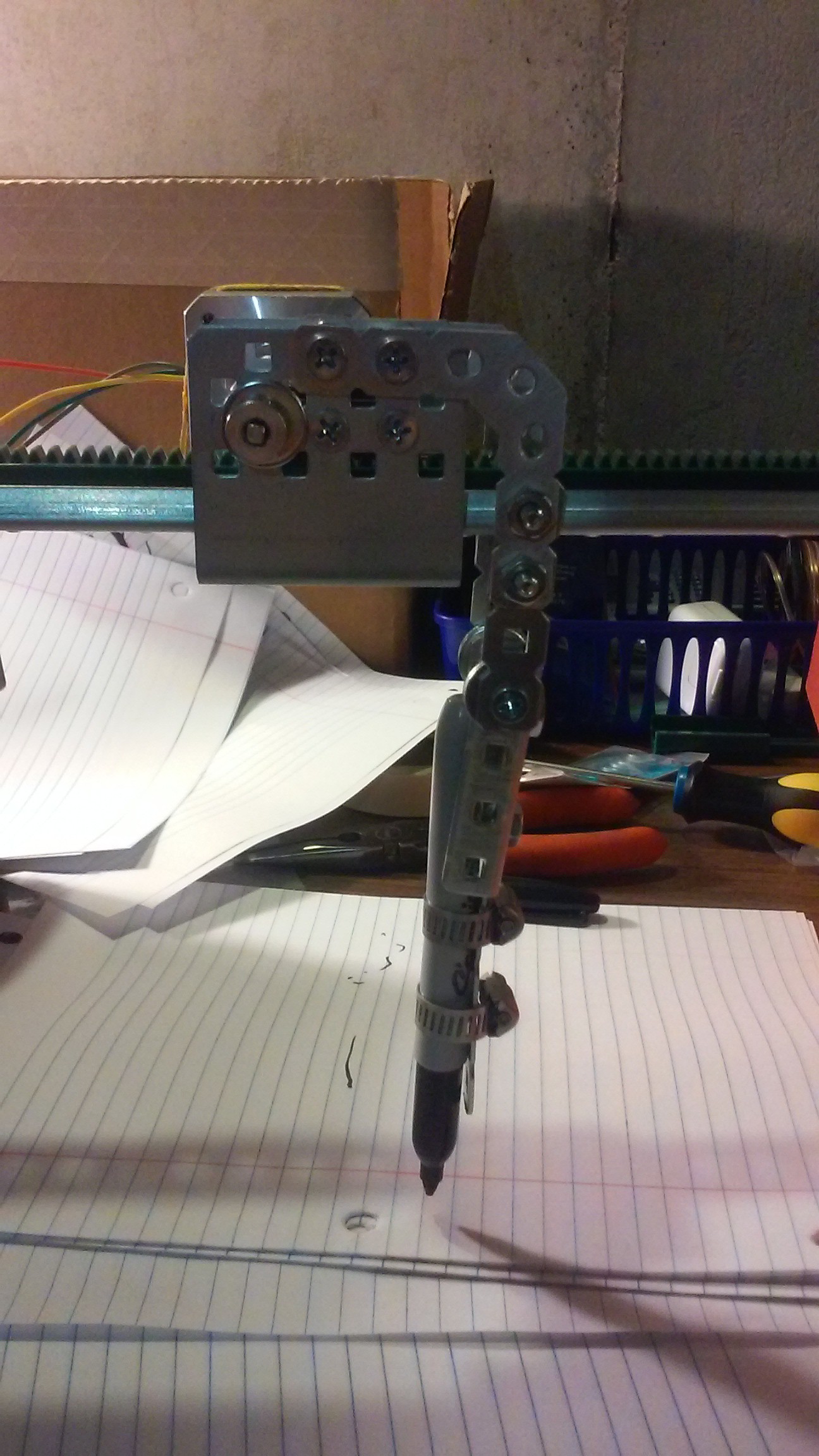
Holding a Pen
08/13/2015 at 17:27 • 0 commentsDuring the initial design stages of the SpiroBot, the issue came up of how the robotic "arm" was to hold the pen. Our particular design required that the pen be able to move vertically to adjust to small irregularities in the height of the platform and drawing surface. Upon doing some research, we found that previous drawing robots used a variety of mechanisms to hold the pen, including adhesive backed cable clamps, rubber bands, and a robotic gripper. However, we found that the easiest method for holding the pen was to use hose clamps, that way the grip would be firm, but easily adjusted to fit any pen or marker.
The initial design had the entire arm swinging up and down about an axis near the top. After building this, though, we quickly found this idea unfeasible, since the pen would dig into the paper and jam the machine when the pen was pushed instead of dragged. Instead, we locked the arm in place and loosened the hose clamps so that the pen was free to move vertically, but was restricted from large movements in other directions.
![]()