CaptMcAllister
-
Road test
11/15/2015 at 15:58 • 0 commentsNovember 15, 2015: I road tested the tire yesterday. A short 12 mile ride along my typical route - I didn't go easy on the tire. Just normal riding conditions.
The first thing I (didn't) notice was the ride. There was no difference in the ride quality. Some have asked me if the huge patch was going to create a wobble or a bounce in the tire. I didn't notice that at all. I think 100 psi forced the patch smooth up against the inside of the tire. The tire itself also has a lot more structural integrity than the tube.
Second, even with pressure on it, I noticed no leaking. The tire came back with the same pressure it went out with.
Finally, and most importantly, the pressure sensor worked at the end of the ride. The RFID still reported the pressure very accurately at the end of the ride. It was a very successful road test. I'm running out of weather to do any more testing this year, but so far it's a good sign. I think I can make it much more durable too, so that will be a focus over the winter.
-
Hackaday post
11/09/2015 at 15:38 • 0 commentsNovember 9, 2015: Whoa! Why didn't someone tell me they wrote up a post. All the sudden the views blew up. :) Glad to hear the comments. To answer the most obvious ones, yes this is a borderline useless project in its current form, but I do hope to make a more mature version someday. The biggest issue is that a full flexible version would cost about $5k up front (and then <$5 per actual patch assembly after that). The second most common comment is to ask why I cut such a huge hole in the tube. This was just for the proof of concept, because the rigid board had to go somewhere - where better than inside the tube? If I hadn't put it in the tube, it would have likely gotten crushed between the sidewall and the tube itself. Again, in a more mature version, you'd probably just need to cut a hole for the pressure sensor port.
-
Functional tire
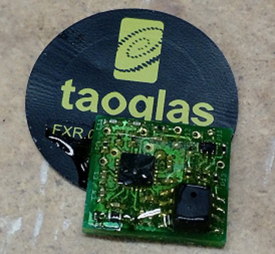
11/06/2015 at 03:47 • 0 commentsovember 5, 2015: Just in time for the end of biking season, I have a sensor tag inside a tire and I can read the pressure quite accurately. To put the tag in the tire, I first coated the PCB in epoxy and I also put a dab of epoxy between the antenna and the PCB. Epoxying the antenna on takes stress off the solder joints which were previously the only mechanical connection between the antenna and PCB. Encapsulating the rest of the components in epoxy is how I'm trying to ensure they won't break off when the tire is rolling. I was careful not to epoxy the pressure port on the sensor shut!
![]()
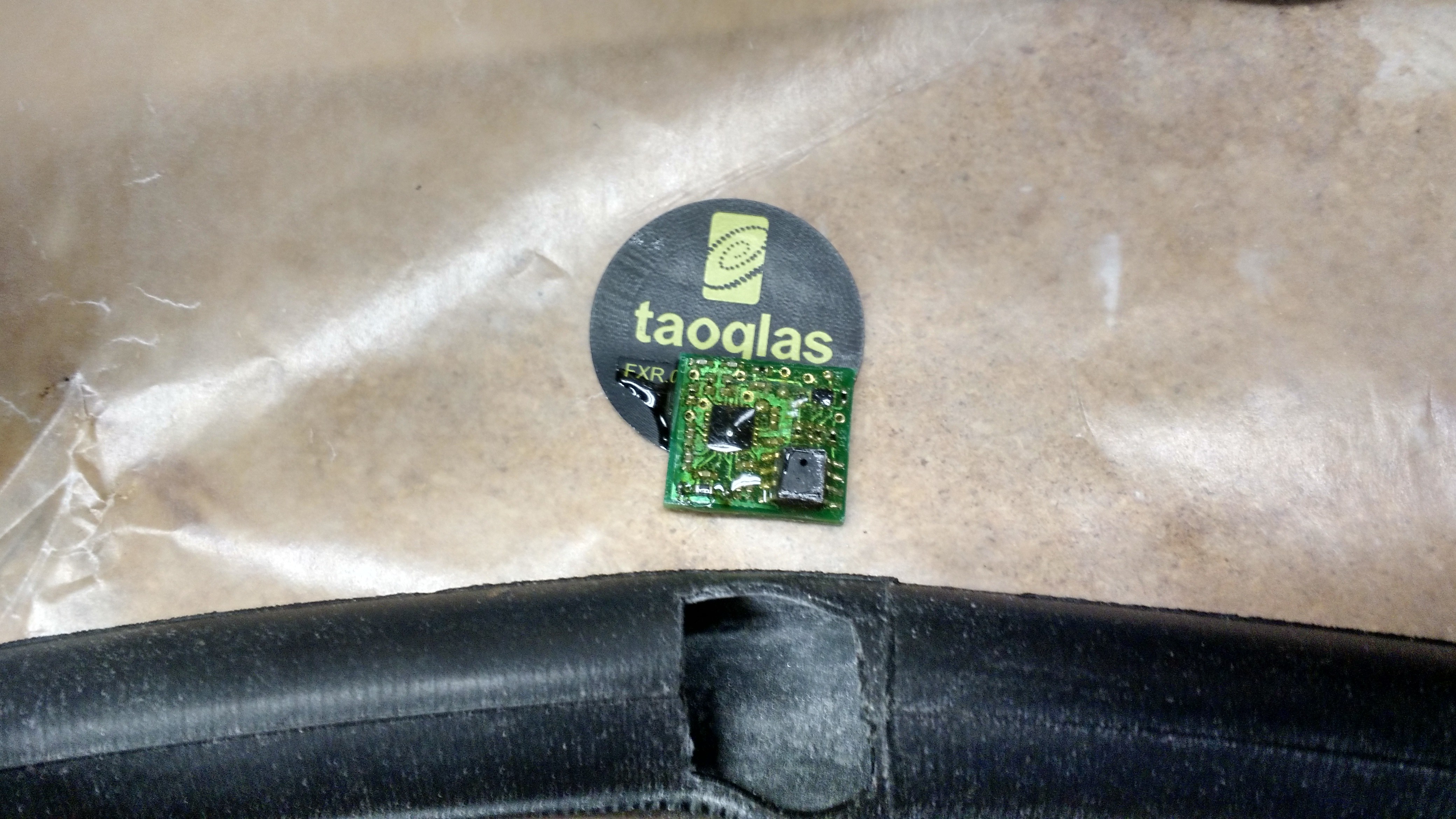
Then I cut a hole in a bike tube that was the size of the PCB. Only the pressure sensor really needs to be aligned with the hole, but I thought it would be less stressful on the PCB if the entire board got to rest inside the tire.
![]()
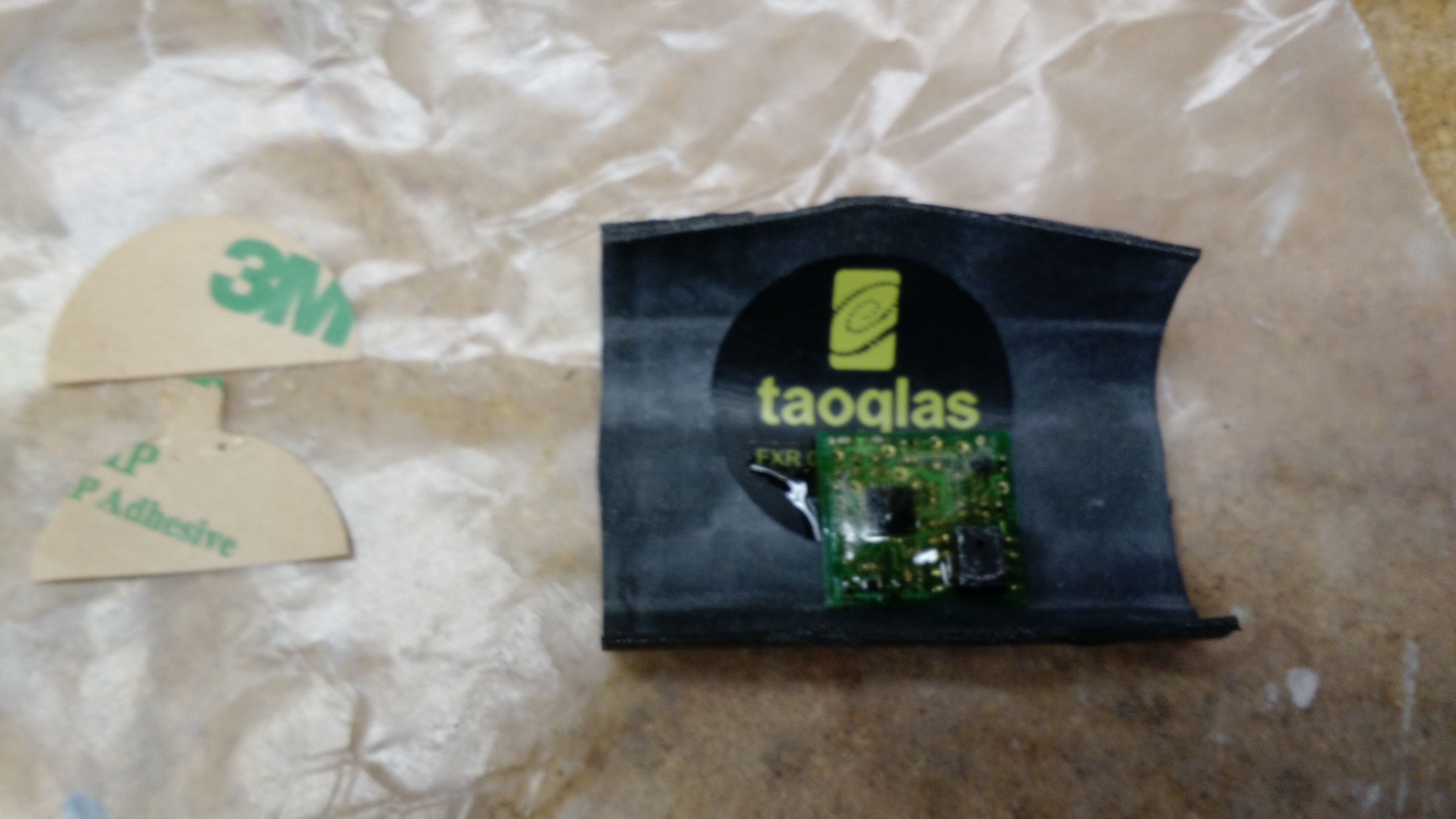
After that, I adhered the antenna to another piece of rubber cut from a different tire tube.
![]()
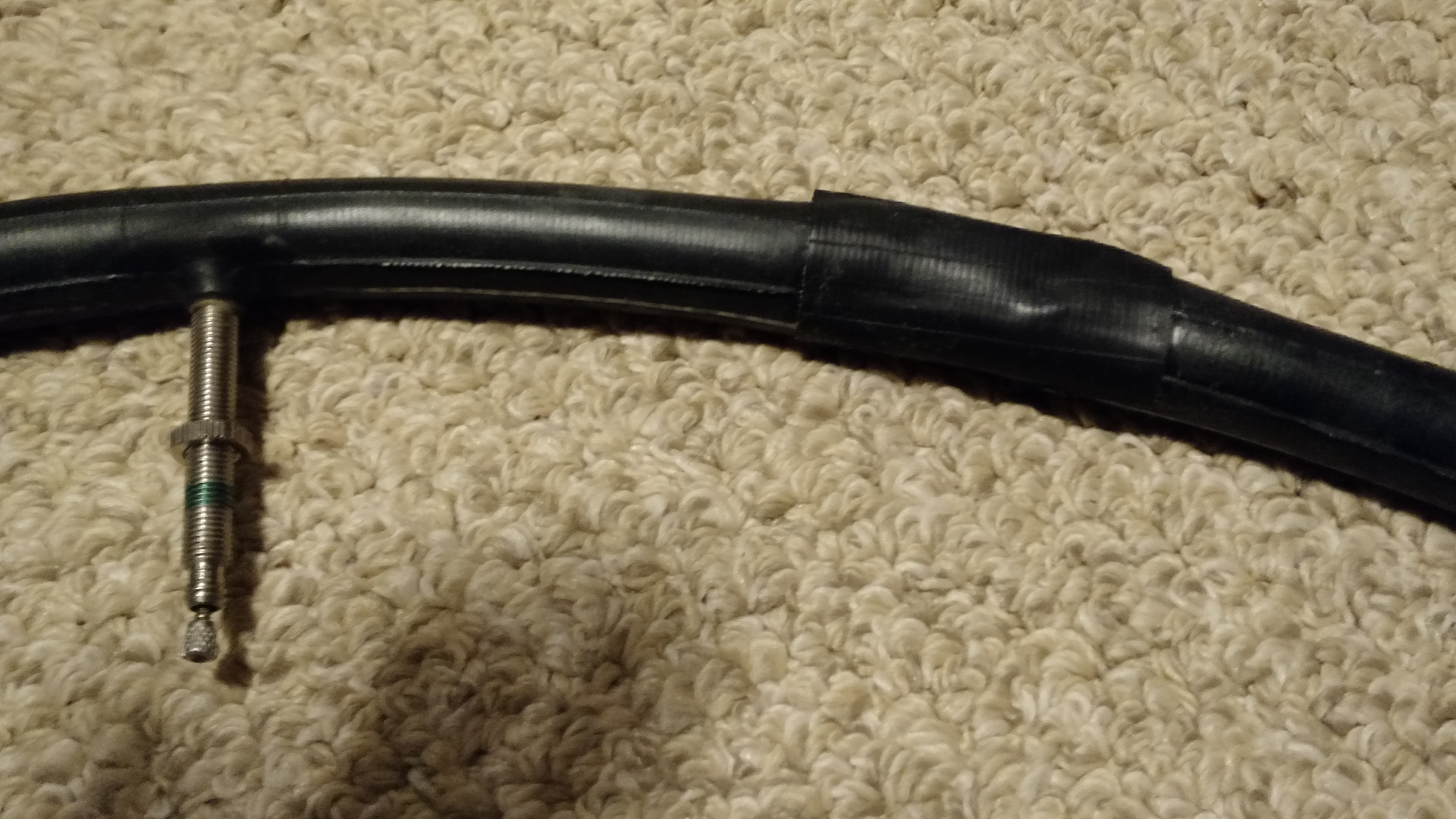
Then I used rubber cement to adhere the patch to the tube, being careful to align the PCB to the hole in the tire. This was kind of a pain, because the patch was hard to get to lie down flat. I should have used some clamps, but it worked out ok in the end. I didn't even notice any leaks when I inflated the tube.
![]()
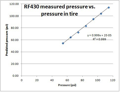
I put the tube back in a tire and pumped it up and took some data. I can't believe the R-squared value on this!
So I think that's pretty much it in terms of proof of concept. It works! The next steps will be to finish a demonstration app and to get some miles on this tire to see how well the patch survives being ridden on. This has been a neat project so far. I think it might work better in a ball or other inflatable where it wouldn't be ridden on. Maybe I shouldn't sell it short though - I haven't tried to ride on it yet.![]()
-
Success!!
10/14/2015 at 02:52 • 0 commentsOctober 13, 2015: Over the past two days, I've made huge progress. I tuned the antenna to provide 3 cm read distance with my phone. I did this by putting 3.3 uH in parallel with the 15.9 uH antenna inductance to yield about 2.7 uH. The IC has an internal 35 pF cap, so I added another 15 pF to this to yield 50 pF total capacitance. Then, 1/(2*PI*sqrt(2.7E-6*15E-12)) = 13.62 MHz, pretty close to the 13.56 MHz reader frequency. Note that this is all possible using only the datasheet numbers. I tried a couple caps on each side of 15 pF and confirmed the read distance dropped off. That told me that 15 pF was the sweet spot.
After that, I applied various analog voltages to the ADC used as the pressure sensor input and confirmed that it acted as expected.
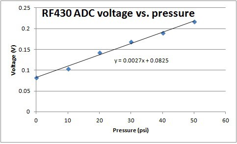
I put the pressure sensor on today and I put the whole assembly in a little box that I built for pressurizing. I tested it at 0, 10, 20, 30, 40 and 50 psi, and got an excellent linear response, just as expected. When I back out the gain of the amplifier and the voltage applied to the bridge, I am within a reasonable distance of the actual pressure. There's still a bit of calibration that needs to happen though.
![]()
So what's next? First, I may jump ahead and try to eliminate the op amp chip. The RF430 has internal op amps, so I might be able to save a lot of space. Then there's a big durability concern to deal with now. This tag needs to go inside a tire tube and get rolled over repeatedly without dying. These two items are next on my list.
-
Prototype readable
10/12/2015 at 03:21 • 0 commentsOctober 11, 2015: I made a bit of a breakthrough today. I finally populated a couple of my boards and put antennas on them, and I am able to read them with my cell phone. There's a picture of the prototype in the pictures section. I am not yet reading pressure, as I didn't put the pressure sensor on yet. I wanted to test the function and tuning of the antenna first. I put a 3.3 uH inductor in parallel with the antenna, but that isn't small enough. I also have 820 nH, but that's too small. I need to get 0402 inductors around 2.6 uH, and then it will be easy to tune. However, right now I can read it about 1 cm away. I'm hoping to hit more like 4 cm, and even then, I'm not sure how well it will do through a typical bike tire. You can get readers with higher power, but that defeats the purpose of the project, which is to read your tire pressure with the cell phone you already have in your pocket.
-
Busy with other projects
10/09/2015 at 02:27 • 0 commentsOctober 8, 2015: I am still working on this, but I have been pretty busy with a few other things. I got the new circuit boards, and I also tested the flexible antenna with one of the old boards. It worked, but the antenna needed to be bent a certain way. I'm hoping it's just because of the messy attach of the antenna to a board that wasn't designed to have an external antenna.
I laser cut solder stencils for the new boards out of Mylar with adhesive. I plan to solder them up in the next week or so, at which time I'll have a sense of whether this is going to work.
-
PCB order
09/08/2015 at 02:13 • 0 commentsSeptember 7, 2015: I had gotten a bit stuck a few weeks ago. I need a flexible design to fit inside a tire tube, but I knew a run of flex circuits was going to be too expensive. Then I realized that my size is really only driven by the antenna. I can't make it much smaller or the power transfer efficiency will plunge. The antenna is really the main thing I need to make flexible. I realized I could wind my own antenna coils from wire, or even better still, buy flexible antennas. I found 13.56 MHz flex antennas for a low cost and I bought some. Then I shrunk the rest of my layout to about 15 mm x 16 mm, and I ordered that circuit board. It should be here sometime in the next week, and I should be able to assemble some sensors and start tuning!
A word about range. Unfortunately, it didn't quite pan out that making an antenna that was closer to the target inductance would improve range. I hit the target inductance pretty much dead on at about 2.5 uH. The tuning cap shrunk from 200 pF, to something like 10 pF. I assumed this meant that more power would be transferred to the 35 pF capacitance in the RF430, and that I would get more range. That doesn't appear to be the case. In fact, TI forum posts on the RF430 seem to indicate that the best range I can hope to achieve with a cell phone will be about 4 cm. You can achieve much greater range with a more powerful RFID reader. However, a major point of my project is to read tire pressure with a cell phone. 4 cm will be adequate, as long as the metal wheel and metal tire belts don't attenuate my signal too much...
-
Origins of the app
08/26/2015 at 01:59 • 0 commentsAugust 25, 2015: I received a sample app from TI today and it reads analog sensors and reports the value on a graph. It's exactly like what I need to read an analog pressure sensor as in this design. I plan on using it with zero changes at first - I will try to select the gain components in my hardware so that the analog pressure exactly corresponds with the temperature. That way, only the units on the graph will be incorrect. The value will be correct - 100 degrees C will correspond to 100 psi. I can change the units and rebuild the graph later.
TI also told me that reprogramming the micro through the RFID reader is supposedly very easy. If I can prove this out, I can get rid of the reprogramming connector and drastically simplify the circuit. This would make the design much more suited for a conductive ink printed design, or for other types of PET design where vias aren't easy.
I started talking to companies about flexible designs, and it will be absolutely necessary for the design in the long run. I've almost gone as far as I can with a rigid PCB design, since it won't fit inside the tire tube. I put the rigid board in a bike tire, and it stood too tall for the tire to seat properly, nevermind the fact that I didn't put it inside the tube for this test anyway.
-
Update
08/22/2015 at 02:08 • 0 commentsAugust 21, 2015: Not too much exciting going on. I've been reviewing the schematic and layout and fine-tuning everything getting ready to order. I also just today looked at the memory map as read by my phone. I was hoping it would be very obvious where the sensor value was getting communicated in the RFID memory. It's not clear to me at all. I read the tag, turned the potentiometer to change the analog value, and read the tag again. I compared the two logs and not a thing is different. I am a bit worried that I'm going to have to dive pretty deeply into an Android app to read the right values. I was hoping it would be easy. I do know I can clearly see a difference running the TI evaluation app with a TI USB reader EVM. Unfortunately, TI does not appear to have provided the source for that evaluation software, so I don't know what it's doing.
-
Antenna tuned!
08/15/2015 at 01:57 • 0 commentsAugust 14, 2015: After tuning the antenna with a shunt capacitor, I was able to achieve a 4 cm read distance with my cell phone. This is a huge improvement from the ~ 1 cm distance before. In spite of this, I think the relatively large resonant capacitor that was required is shunting current away from the IC, leaving less power for it to measure and communicate. Only about 1/7th the current is making it to the IC. I think with proper antenna tuning, I can achieve about 7 times the current, and therefore 7 times the power and sqrt(7) times the distance!
No battery NFC air pressure sensor
Measure tire or ball pressure with your smartphone