Dewet
Dewet-
Engineers Log: 05-26/07/2020
07/26/2020 at 18:58 • 0 commentsSlipping on the cover
After a few weeks getting sidetracked with other projects I finally get to do an update on the NOAHCube. Well actually it no longer resembles a cube in the strict sense of the word but close enough.
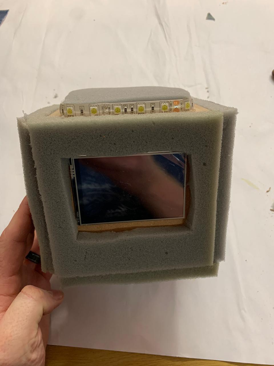
This is my first time working with fabric as a build material and I have to say it was a completely new challenge. In my mind I can now fully envision a whole department at modern companies dedicated to determining the best fabric/material to cover items. There are so many things to consider: stiffness, softness, stretching, opacity, ability to be glued, longevity, resistance to wear and tear, resistance to stains, handling and price to name a few.
It took me so many hours and tries to find the right material I can't even remember everything I tried. In the end the solution was almost comical if you think about all the requirements listed above and all it took was a discussion with someone at the local fabric shop: curtain fabric.
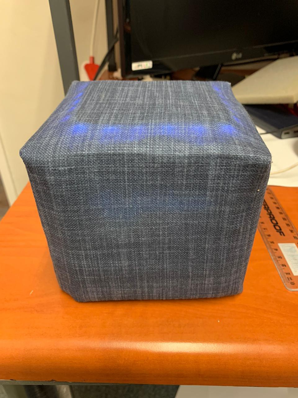
Yes curtain fabric, specifically the kind that has the thick coated lining at the back to keep out extra sunlight. The material met all my requirements and was fun to work with. I used contact cement to glue the edges together and the final result was something I can live with.
Adding the major pieces
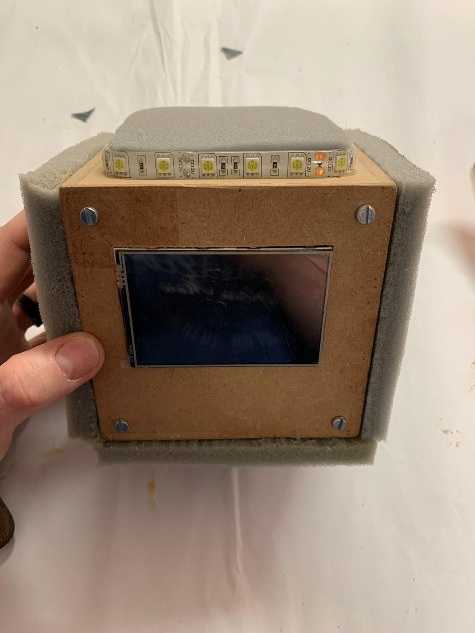
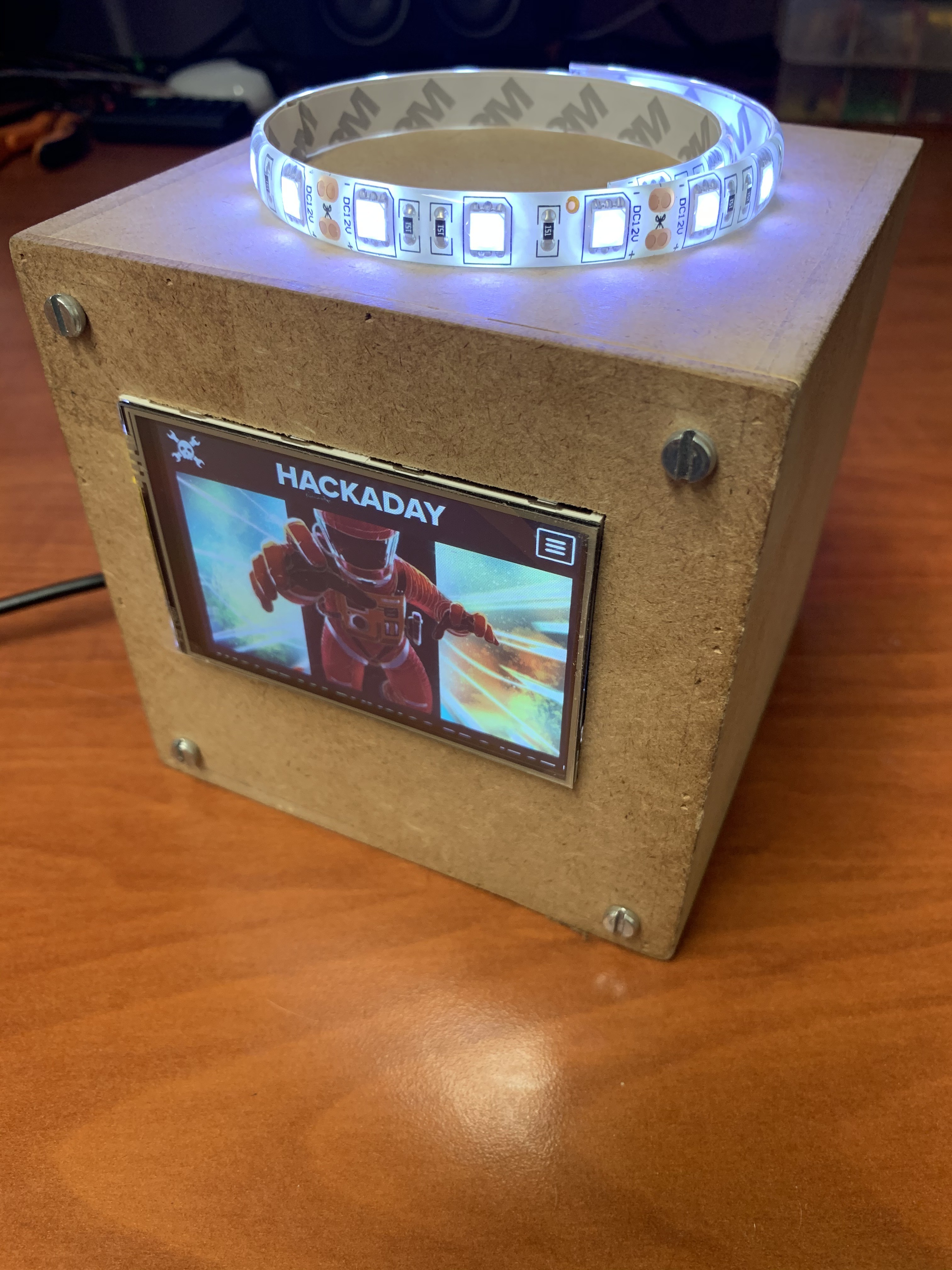
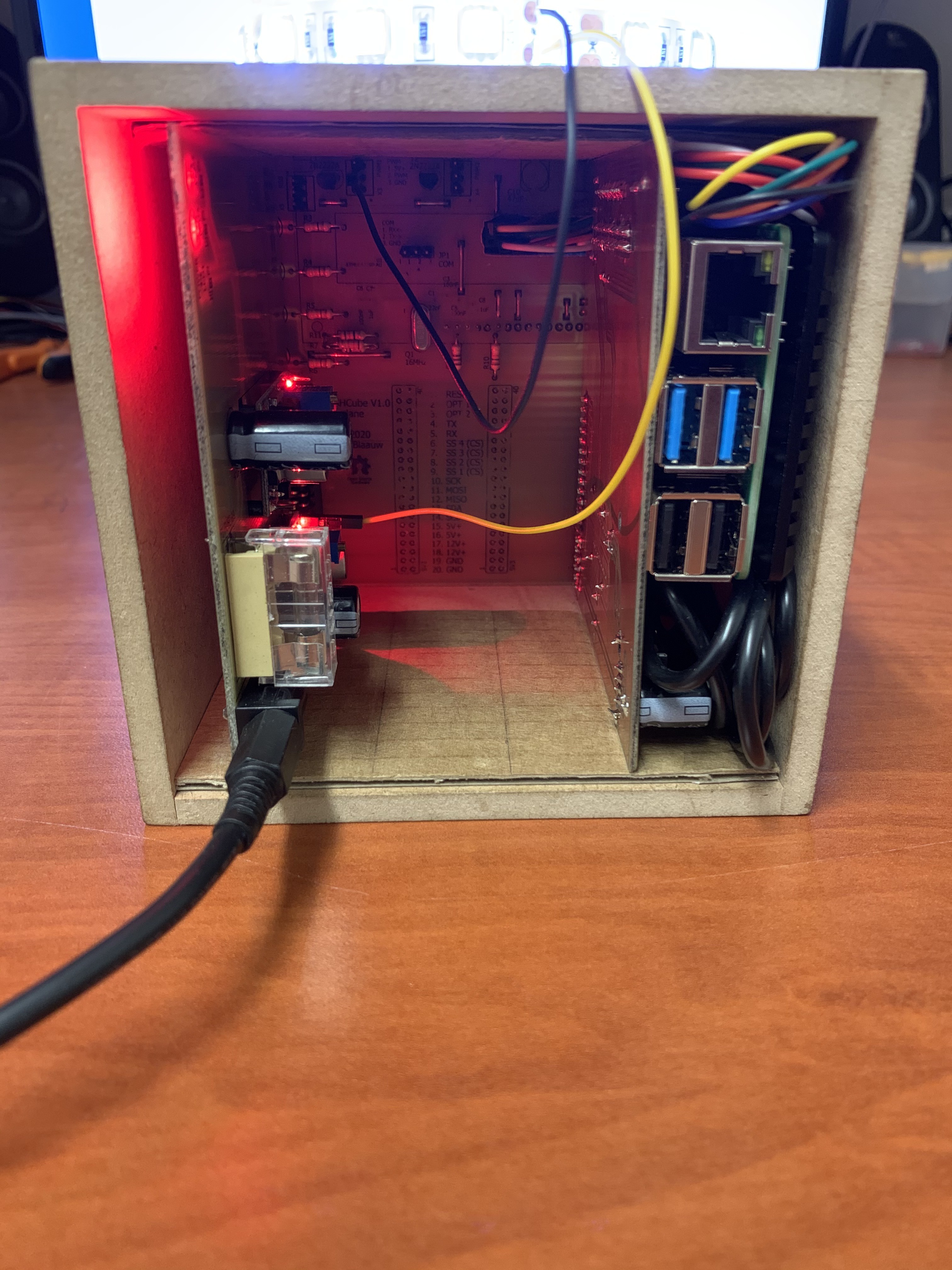
I have since added the new LCD screen, hooked up some white LED strips to test the board while I wait for the RGB as well as writing the code to test the I2C, UART, PWM and other basic functionality. The cube also currently runs OpenHAB and a custom bit of software I will have the LCD display to get access to some audio controls and direct automation control from the front.
My only regret so far is that I had hoped the cube would be able to dissipate enough heat passively that it did not require a fan but alas this will not be the case. The photos below do not currently show the ventilation holes and 80mm fan that I bolted on to solve the problem. Once I am happy with the thermals I will cut the necessary holes in the fabric cover and have the 3D printed bracket made to expose the LCD.
All in all I am happy so far that the prototype is finally up and running. Once the rest of the hardware has proved reliable I will put everything together and have the MDF cube professionally laser cut and the boards sent off to a PCB manufacturer. To the next 3 months of waiting.
![]()
![]()
![]()
-
Engineers Log: 04-02/05/2020
05/02/2020 at 16:59 • 0 commentsThe Status of Things
I can’t believe it has been 2 years since I was last able to work on this project. With life and travel getting in the way I was not able to continue my side projects for a very long time. As is the case in most countries COVID19 has brought everything to a halt in our country and with a full lockdown in effect, I was finally able to spend some long-overdue time on this project.
I started work on the NOAHCube back in 2018 with the idea of building an upgradable hardware platform that I could run my home automation from as well as a few other projects around the house that always seemed to need a dedicated device here or there. Since then nothing much has changed in terms of my requirements so I got to pick up right where I left off.
The Backplane
My initial REV A design for the backplane had a few problems when I finished it back in 2018. These issues have now been rectified in the REV B design and so far everything looks good. The backplane was originally designed to feature a 16x2 LCD to show information and status updates. However, in the last 2 years, 3.5” full-color IPS displays with touch capability have become so cheap that I decided to use this instead of the 16x2 LCD. I did not remove the 16x2 LCD header or functionality so the backplane can still be outfitted with a working display in case I wanted to use the backplane in something else.
Some of the changes I made to the design required me to drop the Arduino compatibility. Even though I wanted the backplane to be Arduino compatible this was just not a feature I needed at this stage of the design but it will remain as a feature that could go into REV C.
So in short, the backplane hardware is now ready and is currently doing the job so far as I can tell. It was also designed to be a bit bigger this time to allow for a better fit inside the Cube and provide some more structural stability for the slot in cards.
I also added a header for RGB LED strips that will fit behind frosted Perspex plates at the top and bottom of the design. I believe adding the RGB strips adds a nice visual cue to alert the user to notifications, status updates, and to be honest in 2020 you just have to add RGB.
POWERCard
The POWERCard was designed as the first slot in card and used to provide the 12V and 5V power rails for the entire system. This card is still in REV A and except for some horrible coil wine on the 5V DC-DC converter all seems well. My idea was to power the cube from a 15-19V 4A power brick and it seems that this is just too much voltage to drop for the 5V DC-DC converter at almost full load, hence the coil wine. As an interim measure, I am supplying the 5V converter with the output from the 12V rail as there is almost no load on it. This temporary fix has taken care of the wine coming from the 5V converter. All tests seem to indicate that the card is sufficiently powering everything including a Raspberry PI 4 B+ while running at full load.
*As a side note, I should have added the ability to monitor current on the 5V and 12V rails so I will add this to the feature list as part of REV B for this board.
CPUCard
I initially wanted to run the system from a Raspberry PI Zero when I created the specifications back in 2018. Since then the PI 4 came out with significantly more powerful hardware so I redesigned the REV A CPUCard to fit that instead.
At this stage, this card is no more than a carrier board so that the PI can interface with the backplane. I wanted to add some additional microcontrollers to this board but with everything the PI 4 offers now and other advancements, I no longer think this will be necessary.
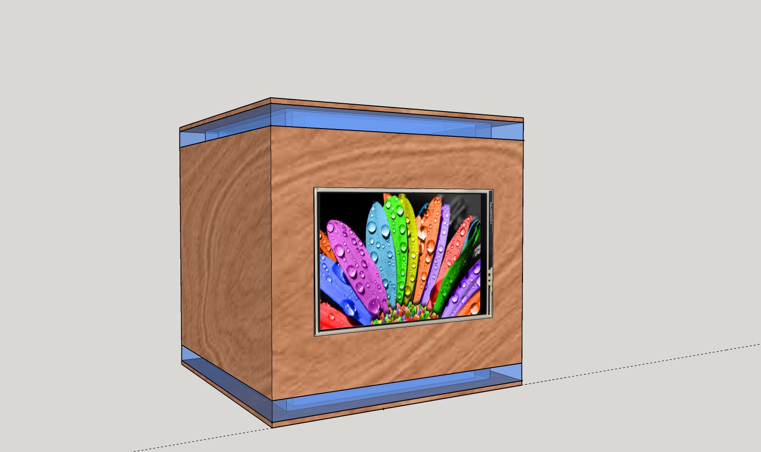
3.5” Touch Screen
This was the most significant upgrade to the design that I made since originally conceiving the cube. With the addition of an IPS 400x360 pixel touch screen this little device now becomes allot more interactive and provides a way of interfacing with device controls directly from the cube.
Final Cube Design
One of the last major items on my list is the look and feel of the cube. I have thought long and hard about how the outside should look and honestly I am still not clear on how to do this one. The idea was to cover the cube in some sort of material resembling a Google Home mini or jean fabric but because this is a cube that becomes very difficult to achieve. When working with a cube there will be seams and I just can’t get something to fit nicely (This might be my total lack of experience in the textile department).
Some more research will need to be conducted to find the right material and method so, for now, the cube will keep it’s stylish MDF prototype looks.
To Summarize
The NOAHCube is now operational and running Raspbian + OpenHAB as well as a custom Java application that I use to fill the screen with some common controls. Thermals are OK under load and there seems to be no risk at present of the MDF catching fire. I have also started work on the IOCard but this will probably only be done at a later stage as all the IO I need to control has already been built and scattered around the house. I am also thinking of working on a UPSCard that will have a LiPo battery and charging circuitry so that the cube can run on battery power in case of power failures.
I truly hope it does not take another 2 years to get to the next phase.
![]()
![]()
![]()
-
Engineers Log: 03-03/06/2018
06/03/2018 at 19:42 • 0 comments*Quick disclaimer, I am not an EE and this is my first ever backplane design so bear with me on this.
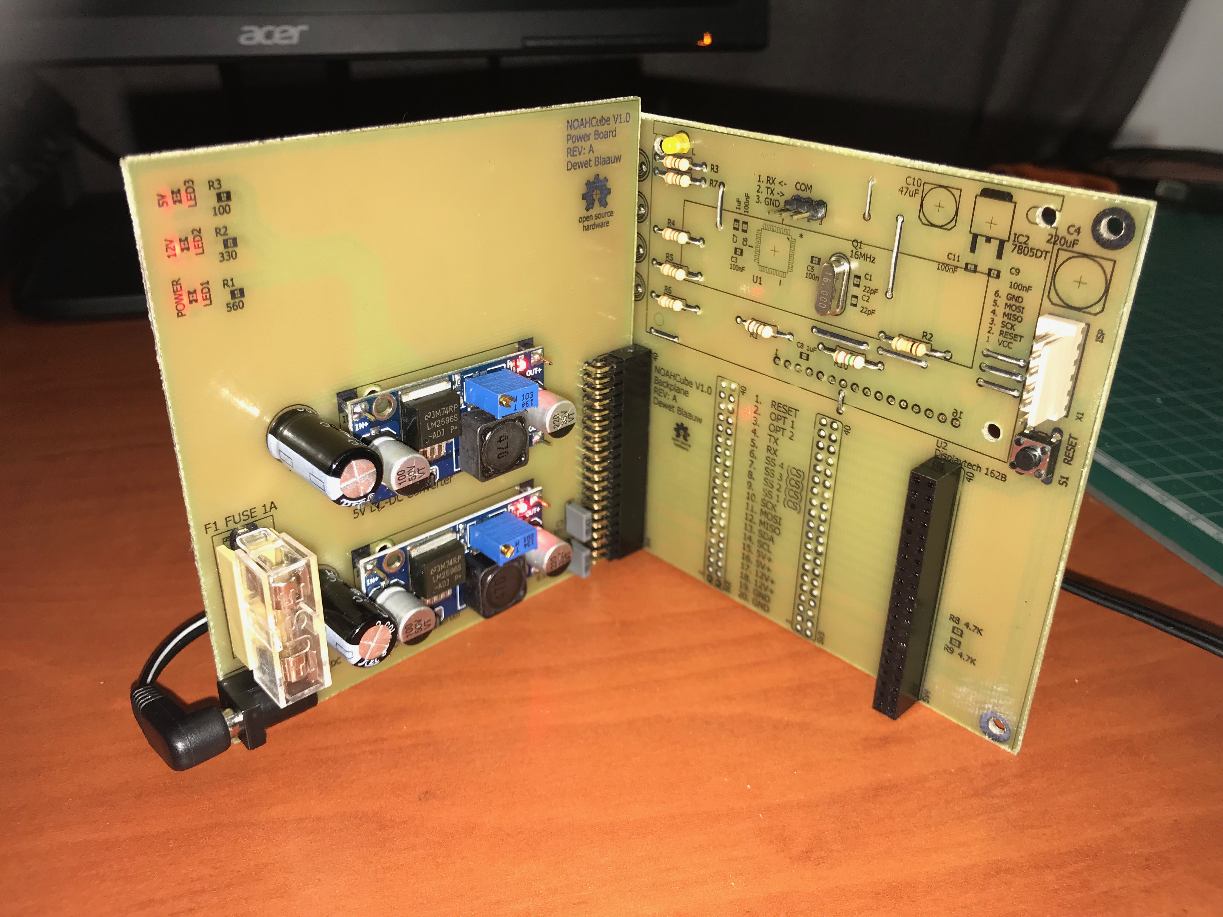
The Backplane
As mentioned in the first log the backplane will be the most important part of this design. It forms the base onto which the other add-on cards will plug into as well as define the future upgrades on the platform.
One mistake here and I will have to work around it for the rest of the projects lifetime. After some late nights, lots of caffeine and a final design sprint, I finally have a design I think will work well. The beauty of the REV: A design is that it is "Arduino compatible", this means you can program it with the Arduino IDE (though you will need to have another Arduino acting as an ISP programmer) or directly with AVR Studio in C/C++. Designing it like this will allow access to the hardware for a larger subset of people that might be interested in building the NOAHCube.
Due to the way I wanted the NOAHCube to operate/be upgraded I designed the backplane to be an active component in the system. I will eventually have an CPU card that will do the heavy lifting but until then the backplane will run the other add-on cards. Speaking of add-on cards, I have the following 4 cards in mind that will eventually plug into the backplane:
1. POWERCard
2. IOCard
3. RFCard
4. CPUCard
* And no I have not given any thought to the naming convention for the cards OK. This will come in time when I have everything up and running and can spare a few brain cycles to think up something creative.
Moving on...
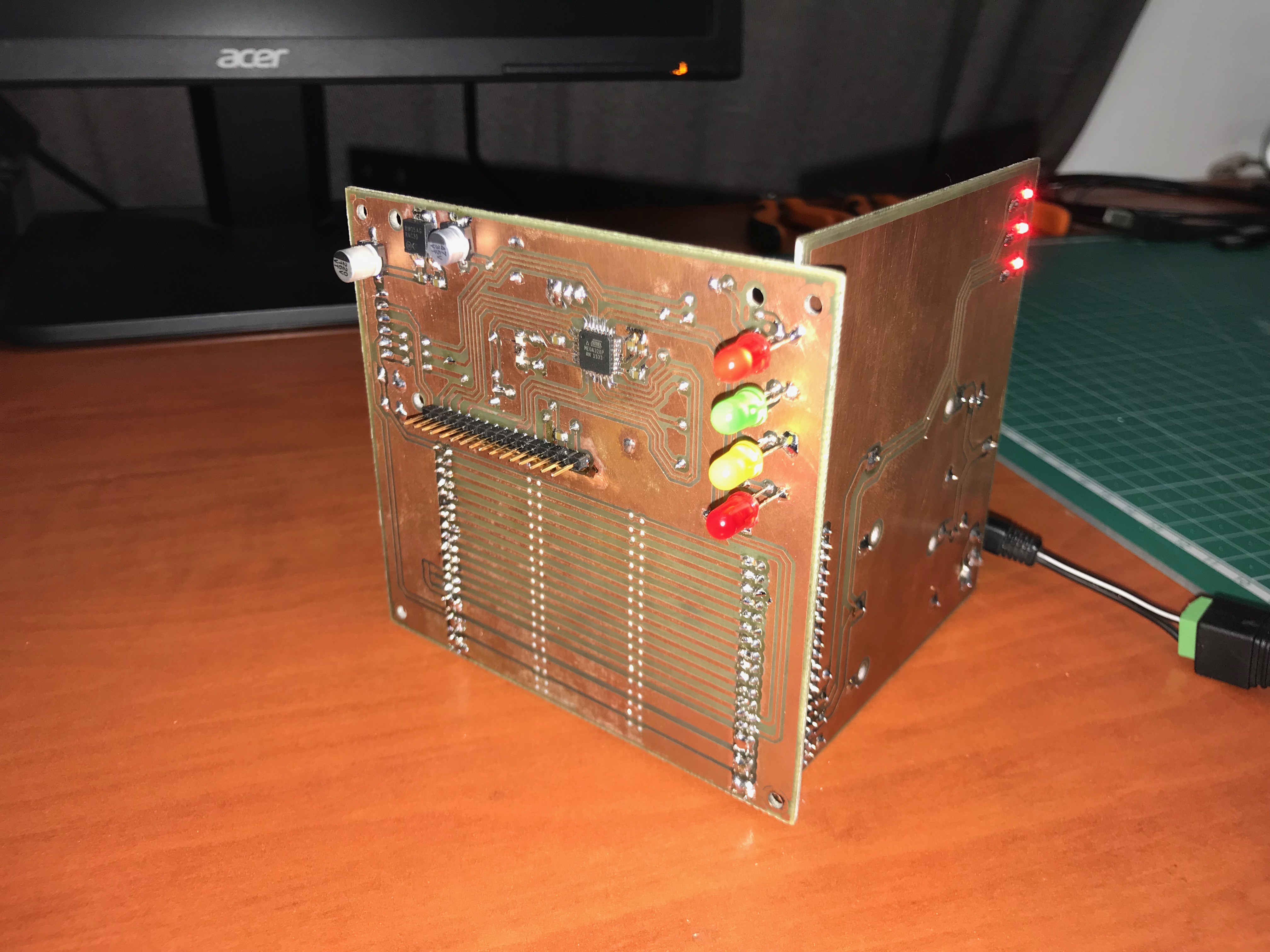
Off course I had to design the POWERCard in conjunction with the backplane as I would need it to power everything up during the initial testing. So currently I have the REV: A hardware for both the backplane and the POWERCard and will add some pictures below. The REV: A hardware has been powered up and initial testing for power and communication on I2C have been completed. I needed to confirm this was working so I could begin with the IOCard next and get this puppy to start controlling some real world stuff. Once the IOCard is done and tested the CPUCard is up next, but I fully expect that to be at least a couple of months off. So in the meantime I get to control a couple of relays.
Excuse all the LED’s and extra pin’s on these boards. They are for testing purposes and will be removed in the final design:
![]()
![]()
-
Engineers Log: 02-24/03/2018
03/24/2018 at 12:07 • 0 commentsMeet the Enclosure
It is a well-known fact that engineers work at their best when we have a set of realistic constraints. So without further ado meet constraint number one, the enclosure. I have thought long and hard about what type of enclosure would suite something that sat quietly on a desk somewhere controlling much of your home.
We all want nice looking enclosures for our smart things. If you take enclosures for smart speakers as an example most of the market is fascinated with rounded enclosures, (think Amazon Echo, Google Home). Now these are great when you have an industrial design team and access to fabrication facilities, but most of us cannot buy these types of enclosures so we must re-purpose something we can find locally or 3D print an enclosure. Since I do not have access to a 3D printer or could not be bothered to design a enclosure in CAD for now, we are sticking to finding something off the shelf.
Based on the above, here are my requirements for the enclosure:
- It should be easily obtained.
- It should be easy to work with. (prototyping requires allot of iteration)
- It should be easy to make yourself in case it cannot be bought.
- It should support the idea of slot in cards/upgradability.
- Did I mention I like cubes, yes a cube shape it will be!
- But most of all it should be cheap.
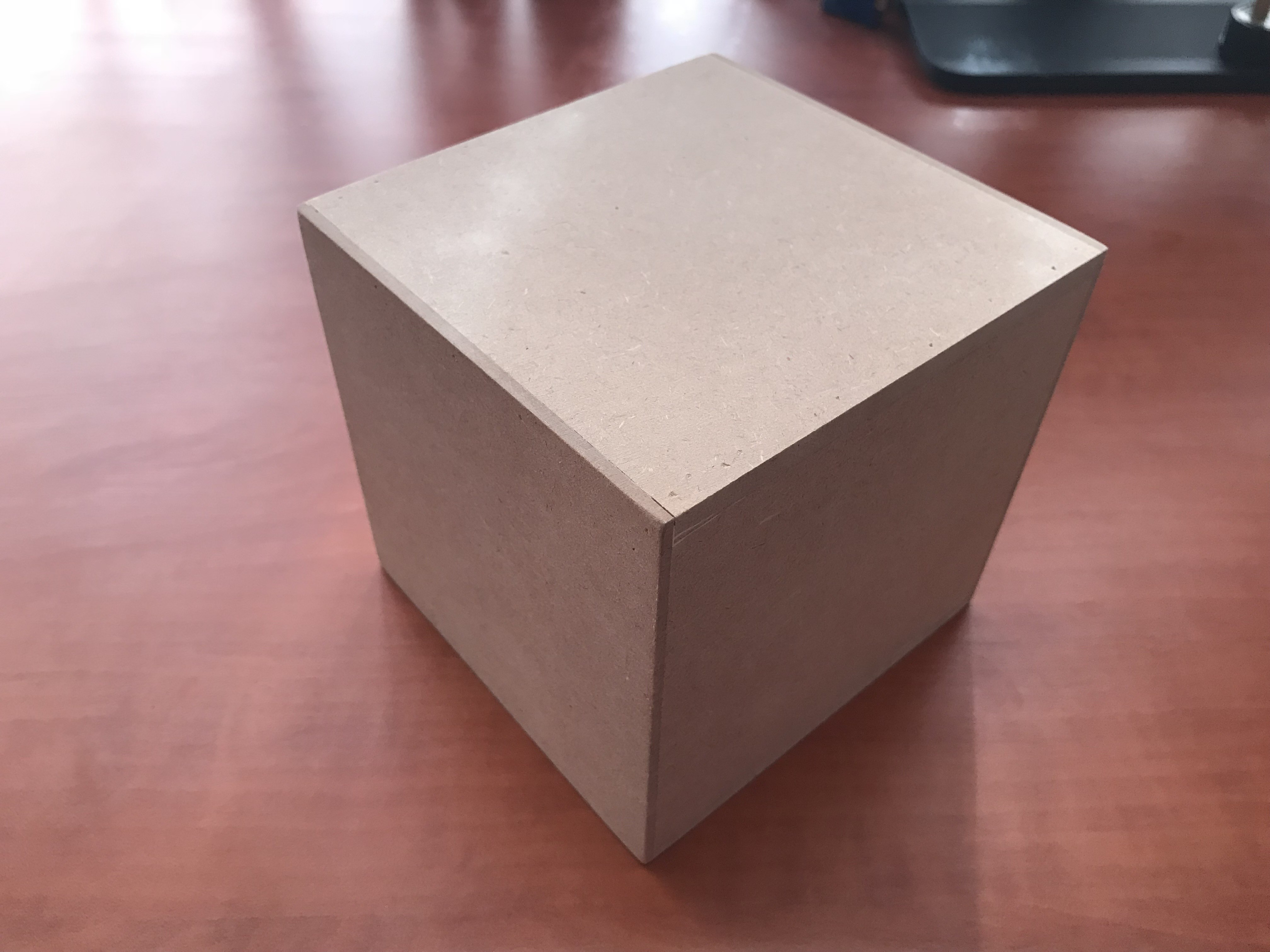
Using the above criteria, I stumbled onto these hobby craft MDF cubes pictured below. You should be able to find them anywhere and if not you can easily make them using a variety of ways. The ones I get are available in multiple sizes but 120x120x125mm seem so be the sweet spot. This allows for (given a wall thickness of 6mm +-) an inner diameter of 108x108x113mm.
For now, this inner diameter is perfect because it will give us space to mount a PCB at the back and with all the support installed, a nice 100x105mm slot in card size.
![]()
-
Engineers Log: 01-02/03/2018
03/02/2018 at 13:41 • 0 commentsWith the project page open it's almost like the first page in a new notebook. You never quite exactly know where or how to start. So the first thing to do is scribble something (really anything) down to ruin the first page so it's easier to start on the next page. This is my first scribble on this project log.
I have the basic idea down for what I want to build and I have a rough idea how. First I need to do some paper work to get the project goals down as well as some specs. Apparently designing back planes for enclosures is an art in itself, see https://blog.lamsimenterprises.com/2011/01/14/backplane-architecture-and-design/ as proof.
First Goals:
My idea for the back plane (a very critical part of this) is nothing too elaborate. We just need the following available to the 4 slot in cards that should fit this design. Nothing high speed here.
- 12V +
- 5V +
- GND
- I2C
- SPI
- SS 1-4
- Serial (RX, TX)
- System Reset
- Optional lines (Spares for future use)
I also need to decide if the back plane should be dumb (no active components) or contain some smarts allowing you to run some of the basics without a CPU card inserted. Important is also to determine what type of connector will work for the back plane.
NOAHCube
The NOAHCube is the next chapter in my Network of Automated Hardware for home automation. A new centralized and portable automation hub