 Ted Yapo
I finally got around to reworking the PCB to route the 4x PLL directly to one of the output drivers. It only took a few mm of wire and a steady hand.
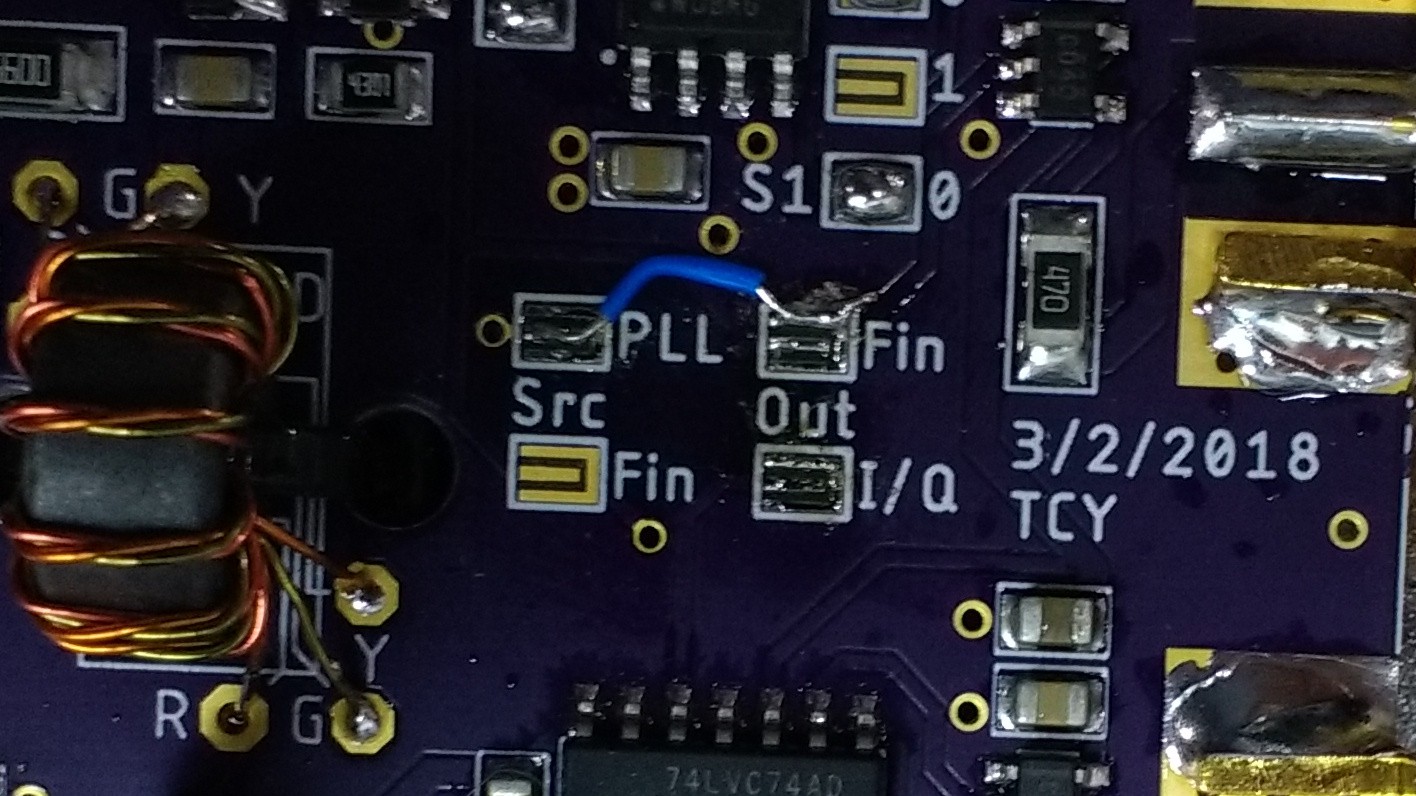
With this mod, the input signal is buffered, the frequency is multiplied by 4, and the result output on one of the ports. I cranked the TG frequency up until the PLL stopped following at 4x (at that point the PLL's VCO just stuck). The highest controllable frequency I was able to get was 296 MHz, shown here on a 300 MHz scope:
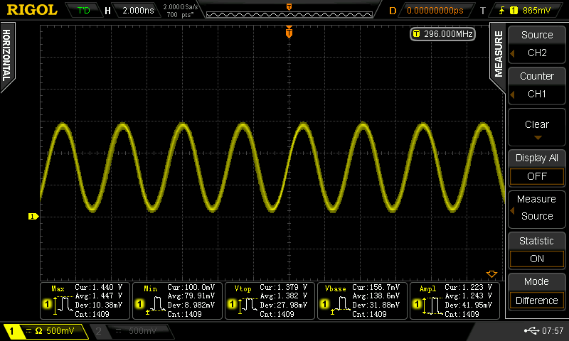
That's what you get when you look at a signal near the scope's bandwidth - everything looks like a sine wave, since none of the harmonics make it through. The input frequency from the tracking generator was 74 MHz (=296/4).
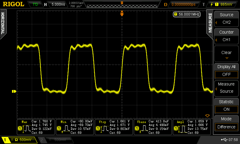
With lower frequencies, the scope can render the true shape more accurately, as shown here for 56 MHz (14 MHz input).
I think based on this experiment, I won't re-spin the board. I have 3 copies of the PCB from OSH Park, so I'll make one of them for I/Q outputs up to 70 MHz, one of them for a single clock up to 296 MHz, and maybe one that skips the PLL to go below 300 kHz.
A DC-296 MHz logic clock will do for the immediate future. That ECL is looking pretty good, though...
Discussions
Become a Hackaday.io Member
Create an account to leave a comment. Already have an account? Log In.
ECL ?...
Are you sure? yes | no
I was looking at ECL flip flops that run at 1.5 GHz or more to generate the I/Q clocks.
Not making my own ECL, if that's what you were thinking :-)
Are you sure? yes | no