Close
0%
0%

Neucuff: A soft orthotic exoskeleton

Neucuff is a simple, powerful, safe exoskeleton for giving Cerebral Palsy patients control over their arms.

Similar projects worth following
Orthotic exoskeletons can be powerful tools for rehabilitation. They offer freedom and independence for anyone suffering from a movement disorder. Unfortunately they can be expensive, difficult to use, and uncomfortable. Small imperfections in the exoskeleton's fit can result in serious injuries. Most devices have to be fit with the help of a prosthetist over multiple visits. This means growing children need many expensive robots and doctor's visits as they develop. Soft robotics offers an avenue to apply force evenly across the body with an exoskeleton that is as gentile as it is strong. Being conformal by nature means a single design can fit a wide range of people just like any athletic brace.

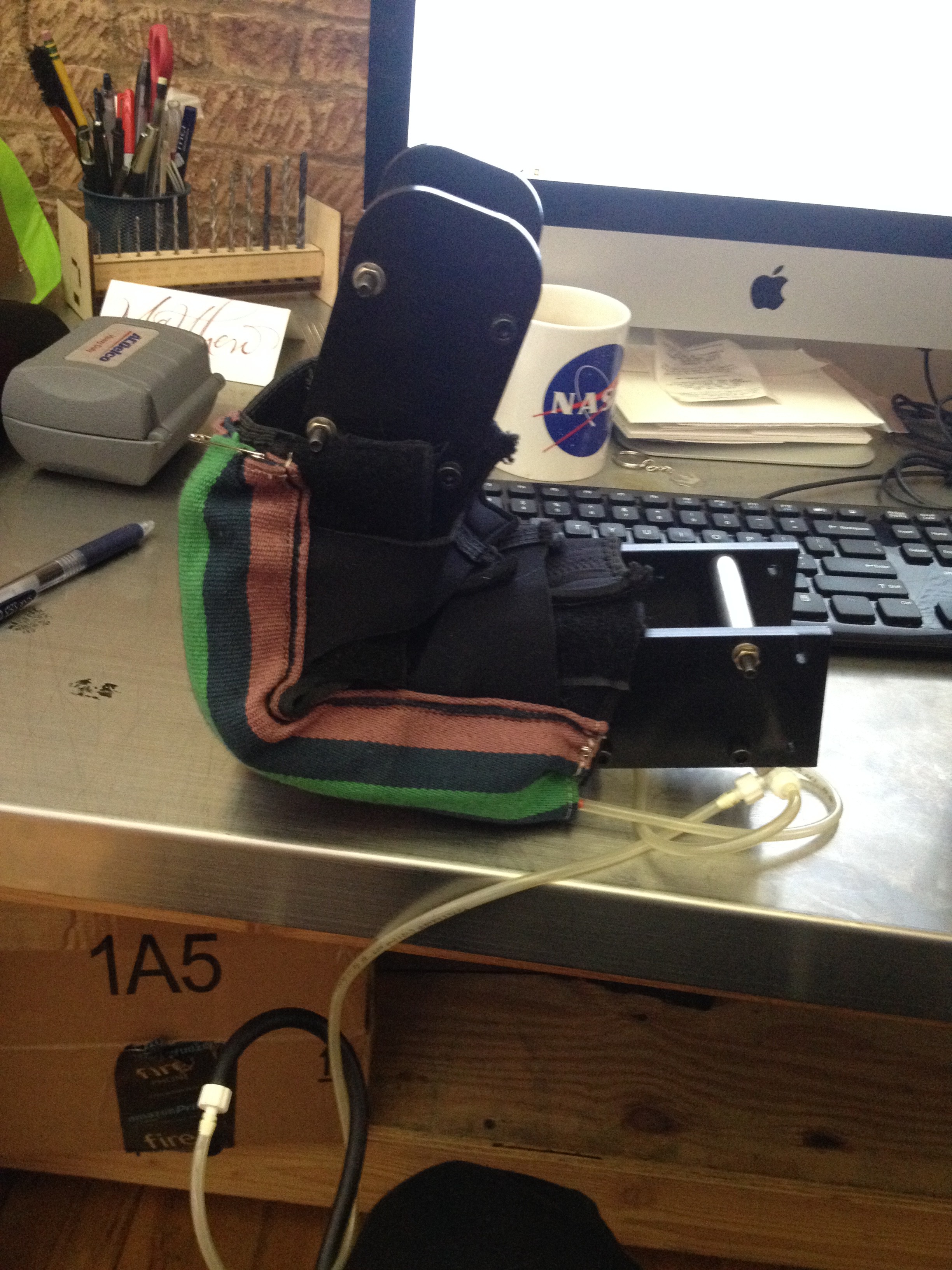
The Neucuff is a soft robotic exoskeleton that's worn on the elbow. It has inflating elements that become rigid as they're pressurized, extending the arm.

[The Neucuff is a research prototype and is not intended for clinical use or sale.]

Why an elbow cuff?

The Neucuff is an extension of the soft robotics research Super-Releaser has been pursuing for the past few years. It is a collaboration between Kari Love and Matthew Borgatti, who have joined forces to blend human factors knowhow with 3d printing and materials science.

We approached a wide variety of people asking where soft robotics could be best applied. we talked with civil engineers about exploratory robots for mapping pipes in construction sites. We talked with NASA scientists about soft robots in space. The most promising ideas came from my father, an orthopedic surgeon specializing in arthroscopy and shoulder reconstruction, and my robotics mentor, who has spent the last ten years in the medical device field.

They both described problems with therapeutic robots that a soft robotics approach could solve. Soft robots are good at spreading force evenly across a large area. Soft robots are conformal so they can fit a wide variety of applications and environments by design. This makes them an ideal candidate for Cerebral Palsy therapy.

What are orthotics for?

Nearly a million people in the US suffer from CP. It's a congenital neurological disorder that causes spastic motion in the limbs, often resulting in a clenched posture. One of the biggest factors in quality of life (QOL) outcomes for CP patients is the ability to use their arms. If you have control of your arms, especially at the elbow, it can mean the difference between being ambulatory on crutches, able to live in a second story apartment, able to drive a car, able to feed yourself, and being dependent on a wheelchair and a caregiver. Devices that improve elbow extension in CP patients have shown huge improvements in QOL, but the current products out there have some major drawbacks.

Soft robots and the body

It turns out that interfacing with the body is pretty hard. If you've ever bought shoes online only to find out there was a subtle but significant difference between the designer's notion of how they should fit and how your body is actually shaped, you know how important fit is. Also, you'll know how hard it is to get something exactly situated on the complex topography of the body. Add on robotic elements, power supplies, sensors, and methods for washing and maintaining that thing over time and you have a serious, complex, expensive shoe on your hands.

If you're a child born with CP, any orthotic device will have to be continuously replaced or re-fit to your body as you grow. Any change means multiple visits to a clinic for adjustments and possibly a huge expenditure on a brand new device. A soft robotic cuff offers the possibility of extending the elbow gently no matter what size the patient is. I picture there being a small, medium, and large cuff, as opposed to an infinite variety of custom tailored solutions.

Affordability and practicality

These design constraints: fit, product life cycle, and manufacturing complexity, make most orthotic robots tremendously expensive. Beyond all the time, engineering, and money it takes to pass the FDA's understandably high hurdles for medical robots, a complex design is simply expensive to produce.

Another advantage of soft robots is that a lot of complexity can be baked into a simple production method. We've made walking quadrupeds out of a single silicone casting. That's 10 actuators fabricated in one simple step. It doesn't matter whether that casting is performed by a person on a lab bench or a machine injecting HTV silicone into a machined mold - the principle is the same. I think that making a technology practical is, in large part, about finding ways to automate its production.

From prototype to product

We are not under any illusions about taking on a hard, complex problem in a field that's already filled with brilliant designers. We don't expect to touch down from Planet Hacker and rock everyone's world in an afternoon. This project...

Read more »

  • 1 × Fabric Backed Neoprene 3mm black
  • 1 × Hook and Loop Fabric 3in wide strips
  • 1 × 3d Printed Molds
  • 1 × Silicone Castings
  • 1 × CO2 Regulator

View all 8 components

  • The Brains

    Matthew Borgatti09/21/2015 at 03:16 0 comments

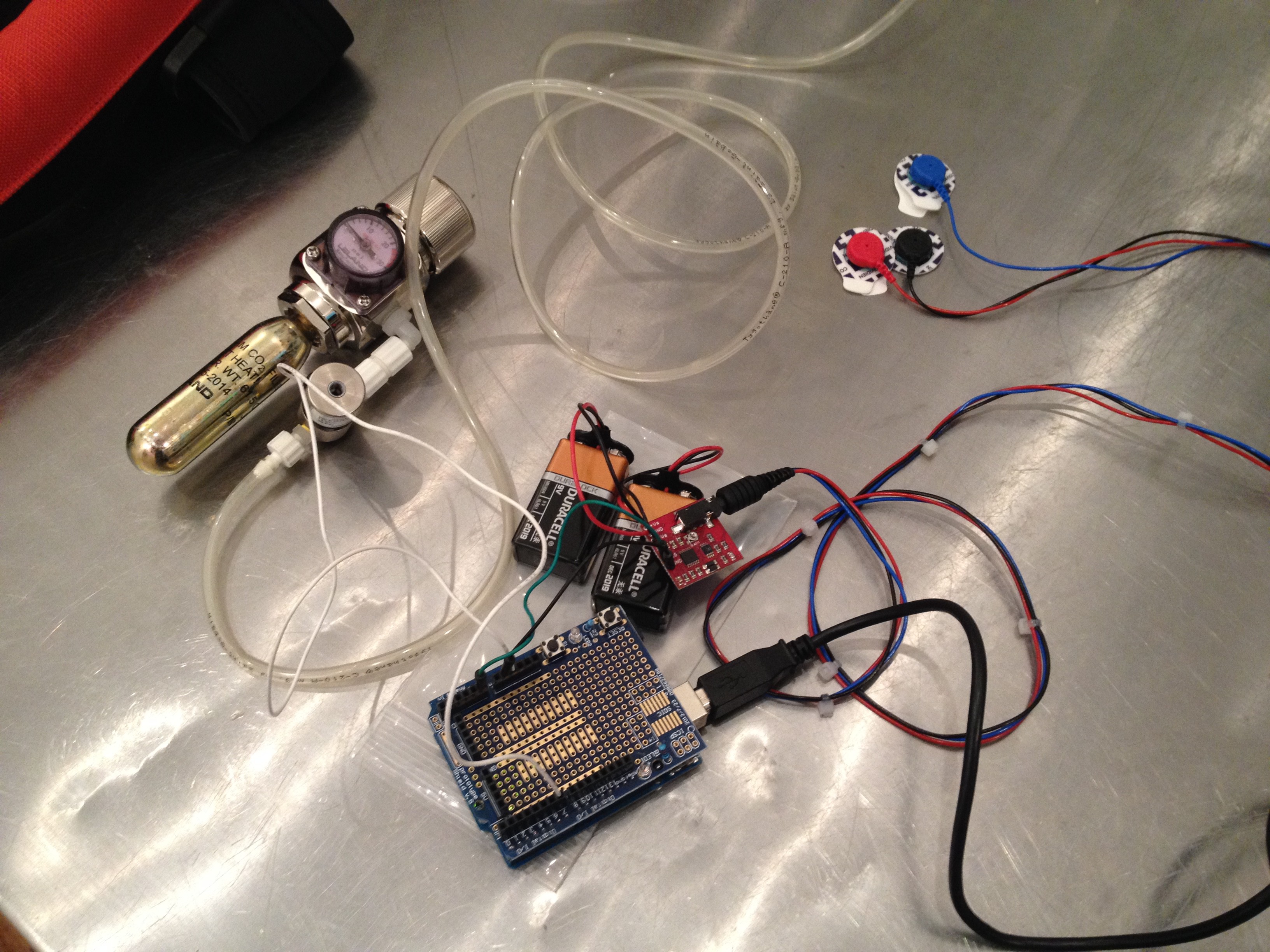
    I'm still trying to get optimal output from my myoelectric sensor, but the above pictures shows the general architecture of the brains of the Neucuff. I've chosen components that don't need a ton of power and could conceivably run for a week off of a single charge of a cell phone battery. Ideally if this device eventually survives the gauntlet of medical evaluation, pilot testing, medical trials, and FDA certification all of the electronics involved can be minimized into a tiny board that can tuck up inside of a package that contains a minimal regulator and the valve.

    The current setup I'm using is a Leiland CO2 regulator with 16g cartridges hooked to a GEMS 12VDC 3-way solenoid valve. The valve is actuated by a signal coming from an Arduino stepped up through a Leivin DC amplifier (not pictured). I'm getting signals from my bicep (technically we'll need to be monitoring the triceps for the "elbow bend/extend" signal but the bicep is easier for testing) via an Advancer Technologies Muscle Sensor V3. The goal is to PWM the valve to achieve the right level of air in the actuators to reach the degree of rotation we're looking for from the elbow. Over time this may require integrating stretch sensors into the cuff to close the loop but there needs to be some more testing before we can make that call.

  • Progress and Prototypes

    Matthew Borgatti09/21/2015 at 02:47 0 comments

    The Neucuff has been a concept for roughly a year. While I was making the Glaucus I tried to imagine where soft robotics could go to offer tangible benefits to peoples' lives. I was able to bend the ears of a few doctors and medical device developers asking what persistent problems in therapy and rehabilitation might find some solutions in the soft robotics field. Cerebral Palsy kept cropping up and I began research and development in earnest.

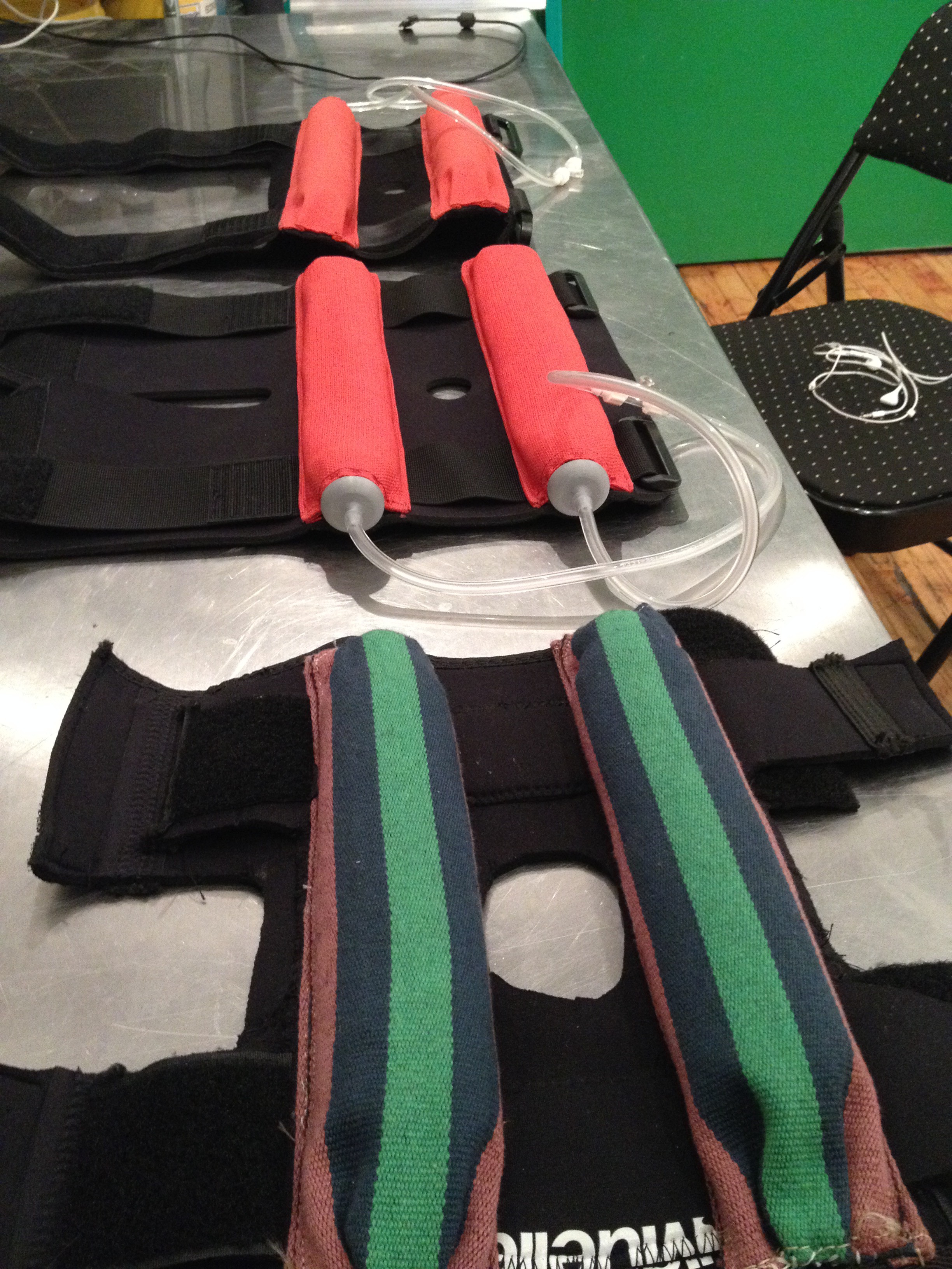
    The first prototype was hacked together from a pair of off-the-shelf athletic elbow braces. Kari Love (who also designs broadway costumes and spacesuits) designed and fabricated the cloth elements, and I provided the silicone bladders.

    The original design used two layers of stretchy neoprene to try and offer a two-step tightening process to make securing the exoskeleton easy for people dealing with motor problems. However, we quickly found that the straightening action of the actuators could stretch the elastic and reduce the amount of force going into straightening the elbow. My first go at high pressure fasteners also proved less than successful when we popped one out of its seat with a small hand pump.

    Those problems were eliminated in the second version, which was laser cut from hook and loop backed neoprene and cordura. Kari designed the flat patterns and laser cut the neoprene and cordura elements. The air fasteners were changed out for the version shown in a previous update. These have proven pretty durable - standing up to pressures of 30psi and above. Again we attempted a two-stage donning process where the exoskeleton would be folded over and velcro'd to itself before being secured with nylon webbing. This time the donning process simply proved too complex and we moved on to another prototype.

    The current Neucuff is made from the same materials and includes a pair of laser cut .25" delrin loops for threading velcro straps. The donning action (seen here) is much simpler. It's also a very secure design that doesn't slip off the arm or loosen over time. This design has enough fidelity to truly evaluate how this kind of device would perform in the field. We've learned that the pressure from the actuators needs to be distributed in such a way as to avoid constricting the inner diameter of the cuff at peak pressure. The force from the straps also needs to be distributed over a wider area with more padding. It's tough to have put in so much work only to poke holes in the latest prototype and go back to the drawing board, but there's no other way to solve tough problems like this. You just keep redesigning and knocking down problems until you reach a model that stands up to a rigorous evaluation.

    For the next versions I'm planning on switching tracks to heat sealed prototypes and am excited to see what comes out of it.

  • Optimizing for Comfort

    Matthew Borgatti09/17/2015 at 23:10 0 comments

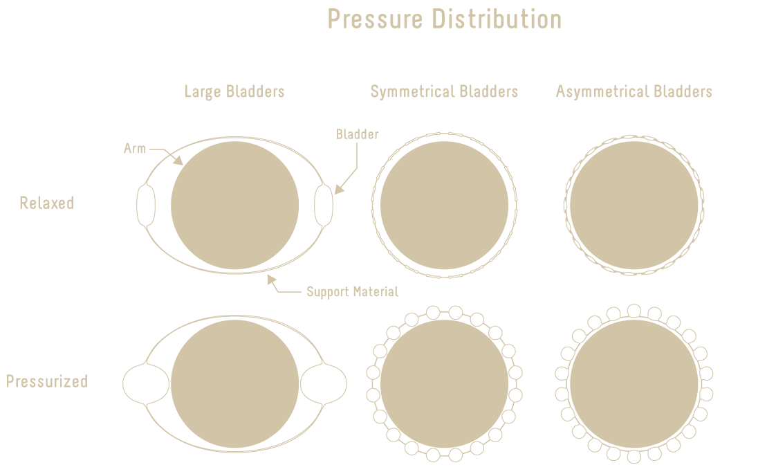
    Now that there is a working prototype and we have gone through a couple of revs it's time to think about user experience. Currently the Neucuff uses two large cylindrical bladders on opposite sides of the arm to provide the torque on the elbow. This is simple and quick to prototype but has two drawbacks: to get an appropriate amount of torque the bladders need to be pretty large and therefore extend pretty far out from the elbow, and as the bladders inflate they attempt to become circular in cross section. This means that, unless the bladders are connected to the rest of the cuff tangent to the circular cross section, they will press into the arm and change the fit of the cuff. If it's fastened loosely the pressure is tolerable but some mechanical force is lost due to the cuff stretching. If the cuff is tight to the arm the decreasing internal diameter quickly leaves pressure marks on the skin which is a no-go for long term wear. If the device is to work as intended (worn all day as an active orthosis) then it's got to distribute the force of the actuators evenly enough to not cause repetition injuries.

    On a base level the torque the cuff applies to the elbow is a factor of the internal air pressure multiplied by the bladder cross sectional area. If we can distribute that area over multiple smaller bladders this would reduce the internal diameter change of the overall cuff. If we continue with the method we are using to generate the larger bladders just scaled down it'll mean a lot of work and tooling to iterate prototypes. However, if we can create the bladders using heat sealing or a similar scale-able process, we can keep experimenting with different possibilities until something hits all the key factors we need.

    Ideally we could heat seal the layers of material asymmetrically as we'd like to reduce the internal diameter of the cuff as little as possible while it undergoes its stiffness change. We have some ideas for creating this system, though it involves an investment in tooling.

    I'll update with more details as they emerge.

  • Systems Overview

    Matthew Borgatti08/16/2015 at 21:12 0 comments

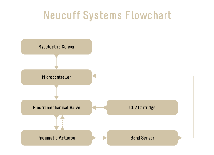
    The basic concept behind actuating the Neucuff is that you can detect intentionality of arm movement in a person with Cerebral Palsy by performing signal processing on their bicep's motor neuron activity. There is some research out there in the medical literature describing methods for achieving this and myoelectric sensing seems like a plausible system for a first approximation.

    I am using the Advancer Technologies Muscle Sensor V3 for the time being, but I'm still exploring other options as I talk with Cerebral Palsy experts to get a better understanding of how intentionality is measured and spastic motion can be mitigated.

    The signal processing will be done with a microcontroller. Hopefully as the design gets refined the controller, the electromechanical valve driver, and the myoelectric sensor can be integrated into a discrete package to reduce the overall complexity. For now I'm using an external microcontroller running some basic programs provided by Advancer Technologies.

    The electromechanical valve will be supplied with CO2 by a disposable cartridge similar to the ones you find in emergency bike tire inflators. They're cheap and energy dense. A CO2 cylinder has about 143 J/g [1] which is equivalent to a Ni-Cad battery [2]. I believe this offers some advantages over a battery. The first is instantaneous torque on the elbow, especially if coupled with an expansion chamber and wider ID tubing to reduce inline friction. It would require a large amperage power source to do the same with a small electric air pump. It also means recharging the device consists of switching out CO2 cartridges rather than plugging in the cuff. It's going to take more testing to validate using cartridges over a battery power source, but the early results are promising.

    The final element to complete the control loop is a bend sensor for detecting how far the elbow has moved relative to the torque the actuators are applying. Since the entire cuff is wrapped around the arm, the material along the tricep and outer forearm will stretch substantially more than the material along the bicep and inner forearm. I believe that integrated stretch sensors along these two lines could easily be compared to compute the angle of the elbow. Whether stretch sensors are manufactured to tolerances that allow precise feedback and other issues will have to be explored with further testing.

  • Air Tight Fasteners

    Matthew Borgatti08/16/2015 at 19:53 0 comments

    You can't get very far in the world of pneumatics without an air tight fastener on hand. One of the persistent irritating features of soft robotics is how difficult it is to fasten an air supply to a robot without some substantial engineering beforehand. For low pressures, cinching up a silicone tube around a harder pvc one with a zip tie can work, but it won't hold for much over 10psi.

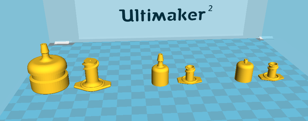
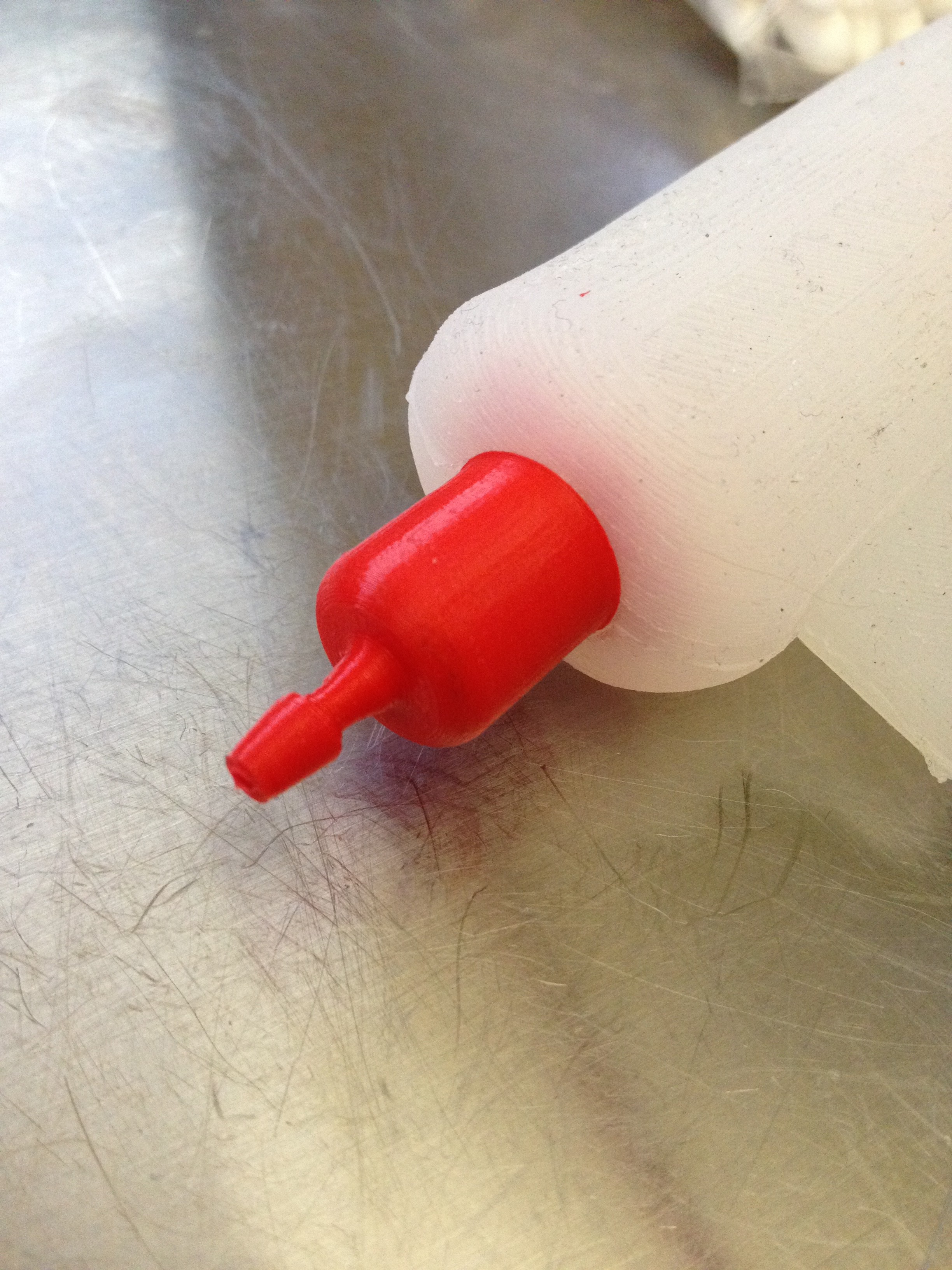
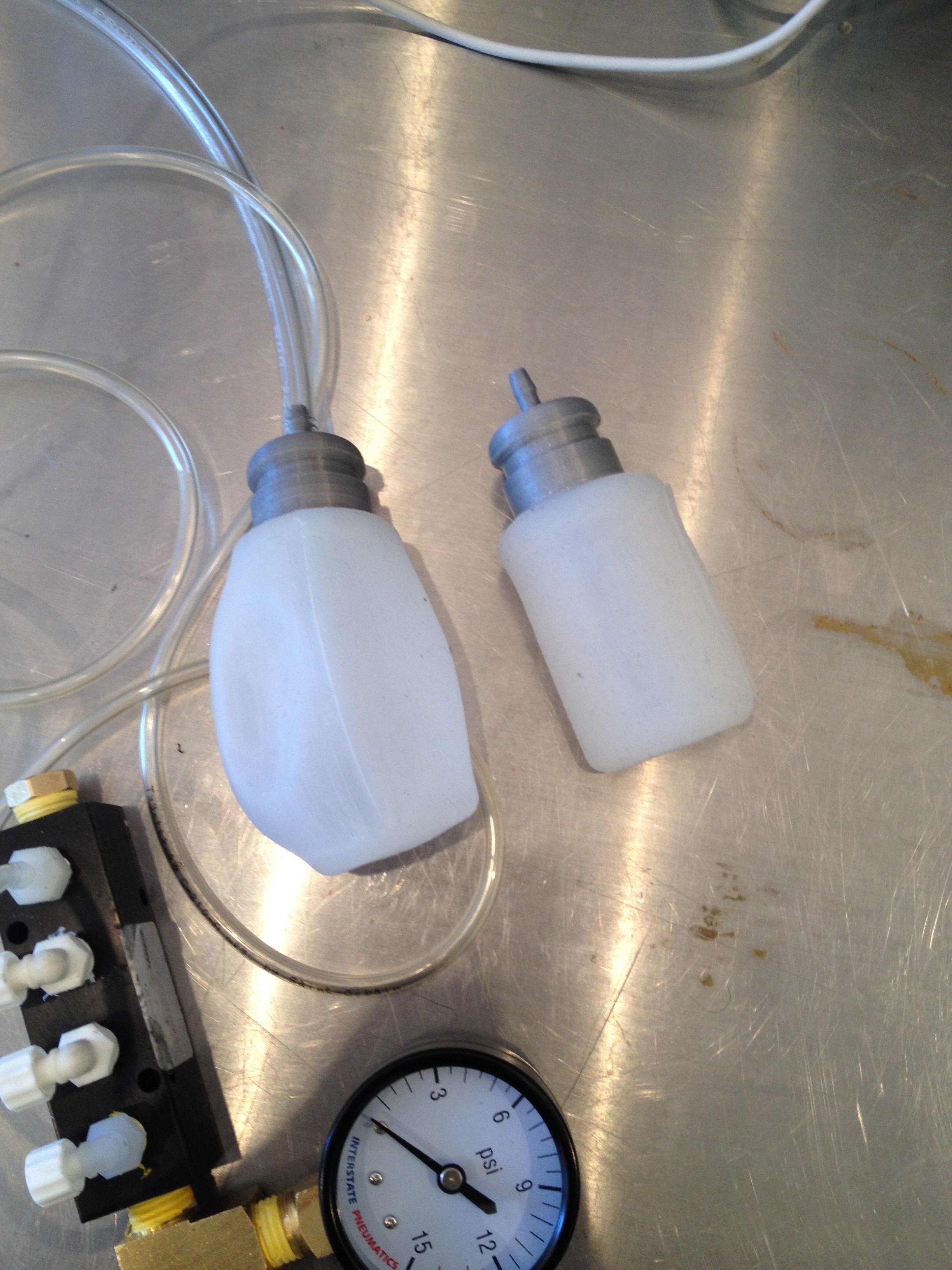
    I've found that the best solution is to integrate a feature like a sleeve or flange into your silicone bladder and then engineer a fastener to fit it. My first two solutions (on the right of the above image) used a straight sleeve projecting from the silicone. You can see a version of the assembled bladder below. This failed at pressures past 15psi. The problem was the silicone around the fastener was stretching perpendicular to the bottom flange of the fastener, slowly pulling the sleeve out of its seat in the fastener.

    The reengineered solution (below) employs a flange cast into the silicone bladder itself. The flange is fed into the top portion of the fastener with a light coating of silicone caulk. Then, the bottom portion of the fastener is screwed on. This fastener has a slightly wider diameter than the silicone inlet, which effectively clamps the flange in place and prevents it from crawling out of its seat as the pressure increases. So far the new fastener design has held up to 30psi, though it could likely hold more. I haven't burst one with this style fastener yet, and I don't want to take it too much higher without a protective container just in case.

    The new fastener also features an external lip for fastening to the exterior restraint layer. This is a trick used in space suits for attaching air hoses and valves. The lip allows the fastener to be seated in a specific position with a few loops of thread before the rest of the stitched elements are assembled. It helps keep everything secure while reducing the finesse it takes to get everything stitched.

    You can download the latest fastener design on Thingiverse.

  • Neucuff Demonstration Video

    Matthew Borgatti08/16/2015 at 19:03 0 comments

    Here's a short video taken at Super-Releaser's lab. It's a short clip from a larger documentary project about the Neucuff that will hopefully be published shortly. In the video I talk with Solomon Israel about what the Neucuff is built to do and how it operates.

    The project is still missing a few components before it's complete on a systems level. The device needs an electronically actuated valve system, a method for measuring how far the elbow has extended, and a method for triggering actuation. After they're all in place, it will still take a lot of experimentation and tweaking to refine it to the product stage. However, there is some really robust research out there on characterizing spastic muscle activity in CP patients and low power valve control.

    I've begun playing with the Advancer Technologies Muscle Sensor v3 and am hoping to use it as the base for experiments creating a measurement and control loop for actuating the cuff.

    The cuff was patterned and fabricated by Kari Love. I provided the cast silicone and 3d printed elements.

  • Testing the First Prototype

    Matthew Borgatti08/16/2015 at 15:36 0 comments

    The first task, once I decided to experiment with an orthotic elbow cuff, was to knock together a quick prototype. Kari and I sourced some cheap athletic elbow cuffs, I fabricated some silicone bladders, and she wrapped them in fabric and attached them to the cuff. Inflating the bladders created noticeable torque on our elbows while we were testing the device, so it seemed like time to gather some data.

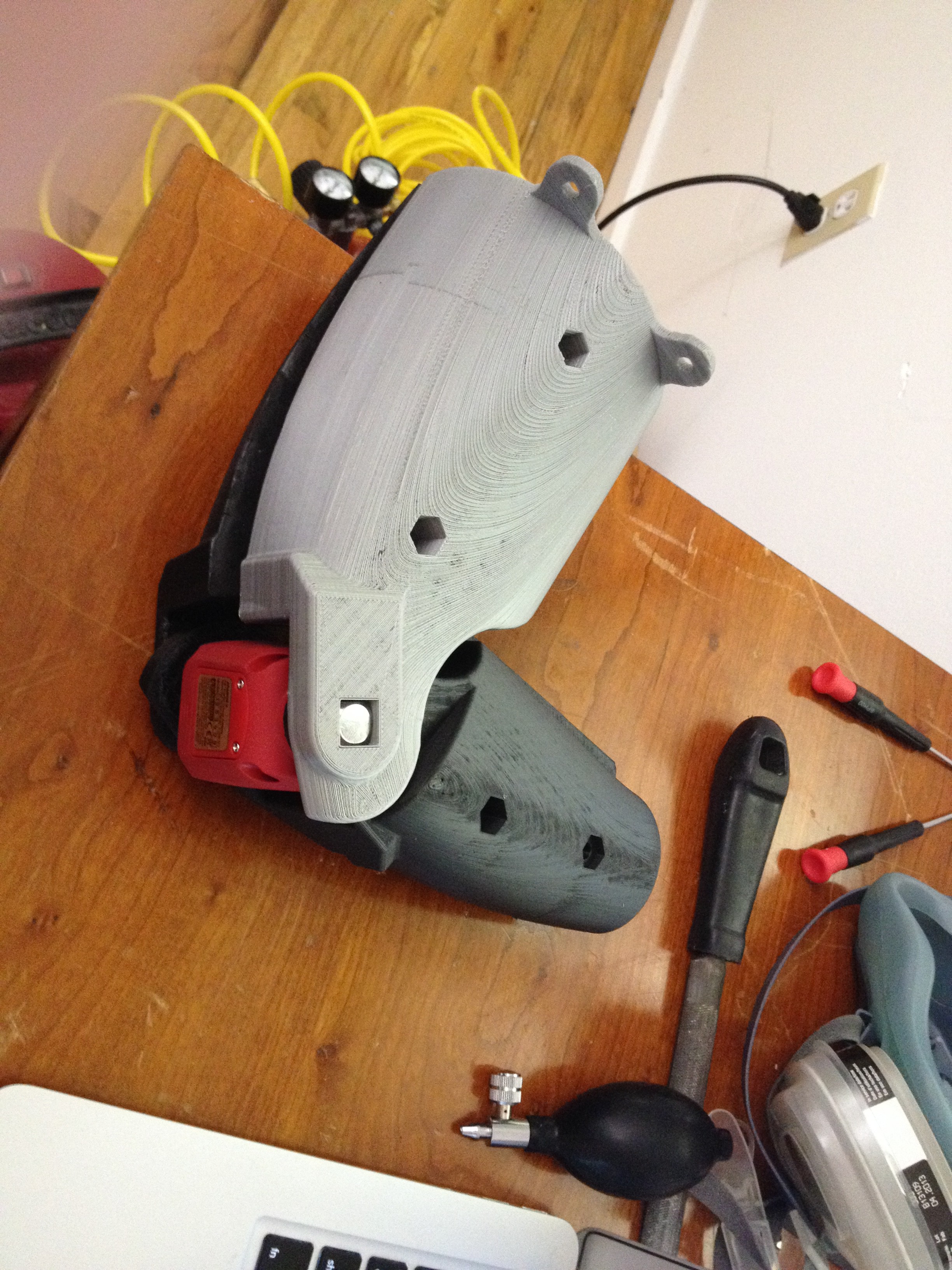
    I tend to prefer to fabricate my own testing equipment rather than sourcing specialty measurement tools. In this case I used an automotive torque meter at the hinge of a simple mock-up elbow. So far I've fabricated two versions of this device: one made of laser cut delrin supported by standoffs, the other a FDM printed elbow based on my own arm. Both could use improvements, especially in how they transmit force to the torque meter. There's enough force at the joint that the plastic deforms where it attaches to the metal meter and it skews the measurement. Still, it's fine for a rough and ready estimate of forces.

    I'll be uploading files for both versions to Thingiverse in time, though I feel awkward about having to qualify them with: "Hey, these meters kind of work but be suspicious of what they tell you".

    It's also crucial to understand where the design starts to fail. The first version of the interior bladder used a small luer-like printed fastener that was airtight up to 10psi. I redesigned it to beef everything up and added a flange to the bladder inlet, which has held up to 30psi without leaking. I'm a little nervous to take anything up beyond that to find its burst pressure without some kind of protective box. Fortunately I have some friends with a blast box in their lab, so it's something that I can tackle in the near future.

    Here's the data from our first test with the delrin torque meter. This is on the first prototype which has a 9" bladder with a roughtly 1.5" diameter.

    TestPeak PSIPeak Torque (ft-lb)
    1154
    2154
    3153.7
    4154.5
    5154

  • How I Started Developing the Neucuff

    Matthew Borgatti08/14/2015 at 17:06 0 comments

    I've been interested in soft robotics for a long time. When I was working in the FX industry about 10 years ago I had a phone conversation with Barry Trimmer at Tufts' Biomimetic Technologies Lab. We talked about ways to use the many mold making and casting techniques used to manufacture movie monsters int the production of laboratory soft robots. That conversation stuck with me.

    A few years later I was part of the fabrication crew on the series Prototype This! It was similar to Mythbusters (in fact, made by the same production company) in that a team of experienced designers and fabricators all got together to solve an engineering problem under a tight deadline. Instead of busting myths, they were building strange machines like pizza delivery helicopters and water slide carousels. I was brought on to help them build devices that would let people climb walls like Spider-Man.

    We explored two methods: van der Waals-based directional adhesion, and insectile tarsi-based spring-loaded hooks. The first is employed by geckos, and leverages the tiny intermolecular force atoms experience when very close to one another. In a rough-and-ready way: if you can get two surfaces to touch without an air gap or water between them, they will feel a very slight attractive force. The more surface area you've got, the stronger the force. Geckos have tiny spatula-like fibers on the pads of their feet called spatulae, which are arranged like feathers on a feather duster on the ends of hairs called setae. These offer boatloads of surface area for contact and can conform to surface features from the 1mm scale all the way down to 1um. The other adhesion method we used is very similar to how flies stick to walls. Flies have hook-like hairs on their legs that are biased to grip when the leg is raked across a surface in a particular direction. As long as that leg is putting pressure on the wall in that direction, the hairs engage with the surface and the fly is stuck.

    We made versions of the geckoadhesive gripper using pressure casting and machined molds. The most difficult part of getting successful pulls from our molds was how fine the hairs were, and how likely they were to just tear off the silicone pad and simply stick in the mold. Eventually we found a solution that produced spatulated hairs pretty reliably.

    [This video showcases the tarsi gripper method, as well as the engineering of JPL mech-e Aaron Parness, who I worked with on the Prototype This! devices.]

    What was even more fascinating was the manufacturing method behind the tarsi gripper. This involved facing a huge block of wax, etching temporary molds, casting these molds with a two part urethane, machining features into these parts (still locked in the mold) for placing hooks and casting in a second layer of softer urethane. The resulting spring mechanism was sincerely brilliant. It was biased to change the hook's angle based on the force applied and bouncing it up out of whatever feature it was clutching when pressure was removed. It was a simple part with a very simple manufacturing process that exhibited a complex behavior.

    That concept has influenced a large portion of my work: the right manufacturing process can simplify even the most complex mechanism. I realized how powerful compliant mechanisms can be and how nature has employed them everywhere to solve mechatronics problems.

    I didn't start seriously experimenting with soft robots myself until I met Jim Bredt. Jim is one of the founders of Z-Corp and runs a 3d powder printer research lab in Summerville. He offered to queue up some designs on his printers in exchange for some help around the shop and time evaluating some of his experimental manufacturing processes.

    I started producing simple pneumatic actuators like tubular tentacles and inflating patches that would bend with pressure. Soon, I established some reliable manufacturing techniques like lost wax casting for creating interior geometry in seamless silicone forms. I made the Glaucus...

    Read more »

View all 8 project logs

Enjoy this project?

Share

Discussions

architecnologies wrote 09/12/2017 at 21:13 point

Am obtaining intellectual property protection for a product.

Would you be interested in possible collaboration on a part of this product.

It involves, pneumatics similar to your device

Thanks

Frank (arch616135) (architecnologies@yahoo.com/simplifiidesign.com)

  Are you sure? yes | no

Similar Projects

Does this project spark your interest?

Become a member to follow this project and never miss any updates