 Muth
Muth-
1Step 1
The Thermal Printer
The most delicate part is to tweak the thermal printer. Some details are there : https://hackaday.io/project/3917-pi-print/log/13184-thermal-printer-adventure . To summarize, there is two step to achieve:
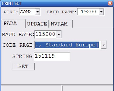
1 - This printer receives data on a serial port, and by default the speed is slow. And there is a software way to change from 19200 bauds to 115200 thanks to this program: Link. As it is a windows program, we need a USB to 5v TTL serial converter, such as this one. Power the printer, connect the gnd-Tx-Rx, and on the printer program set the right port, the previous speed (19200 in my case), the new speed (115200), code page US (it's the character-set ) and press SET.
![]()
If this step is impossible, see instruction 7.
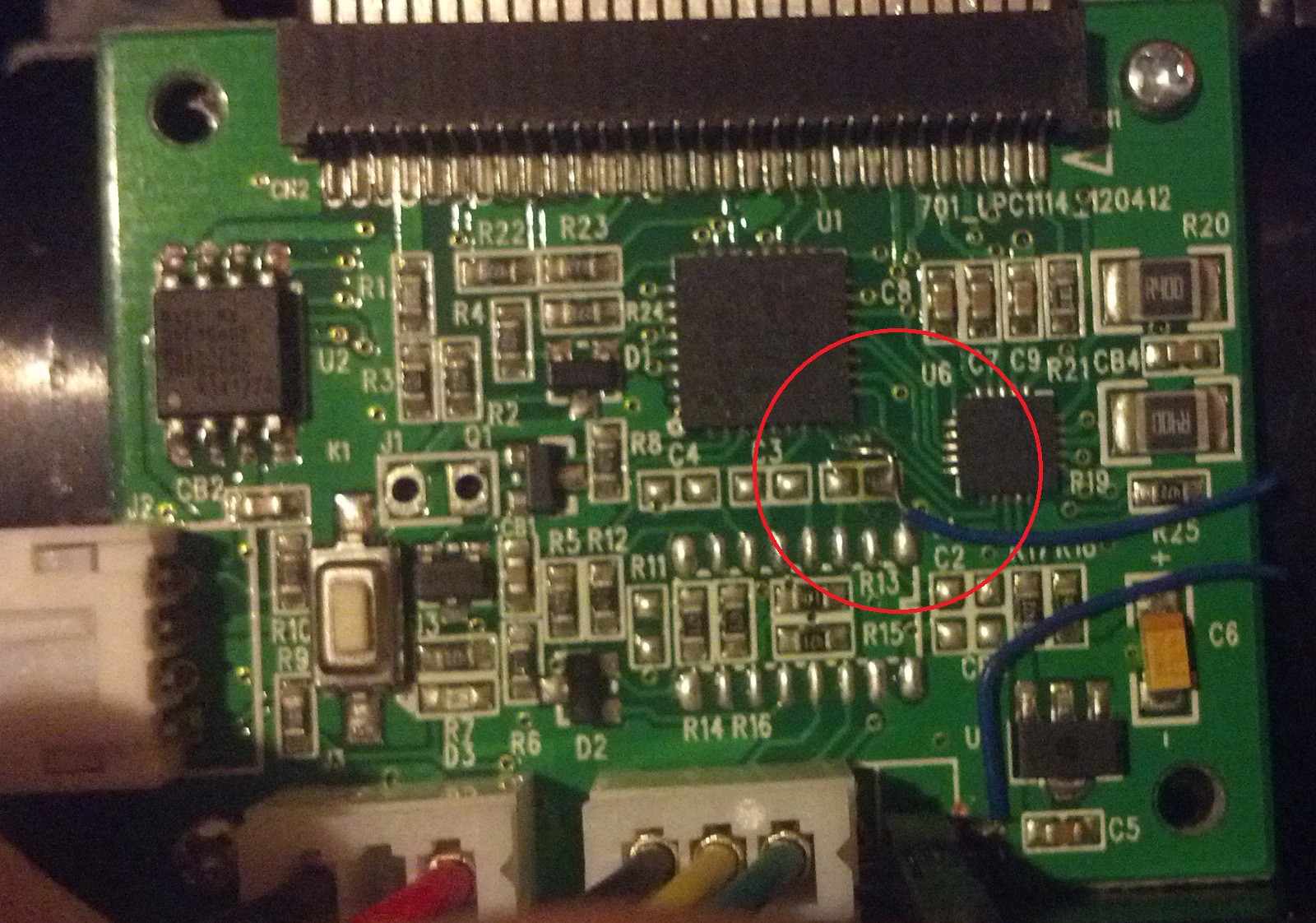
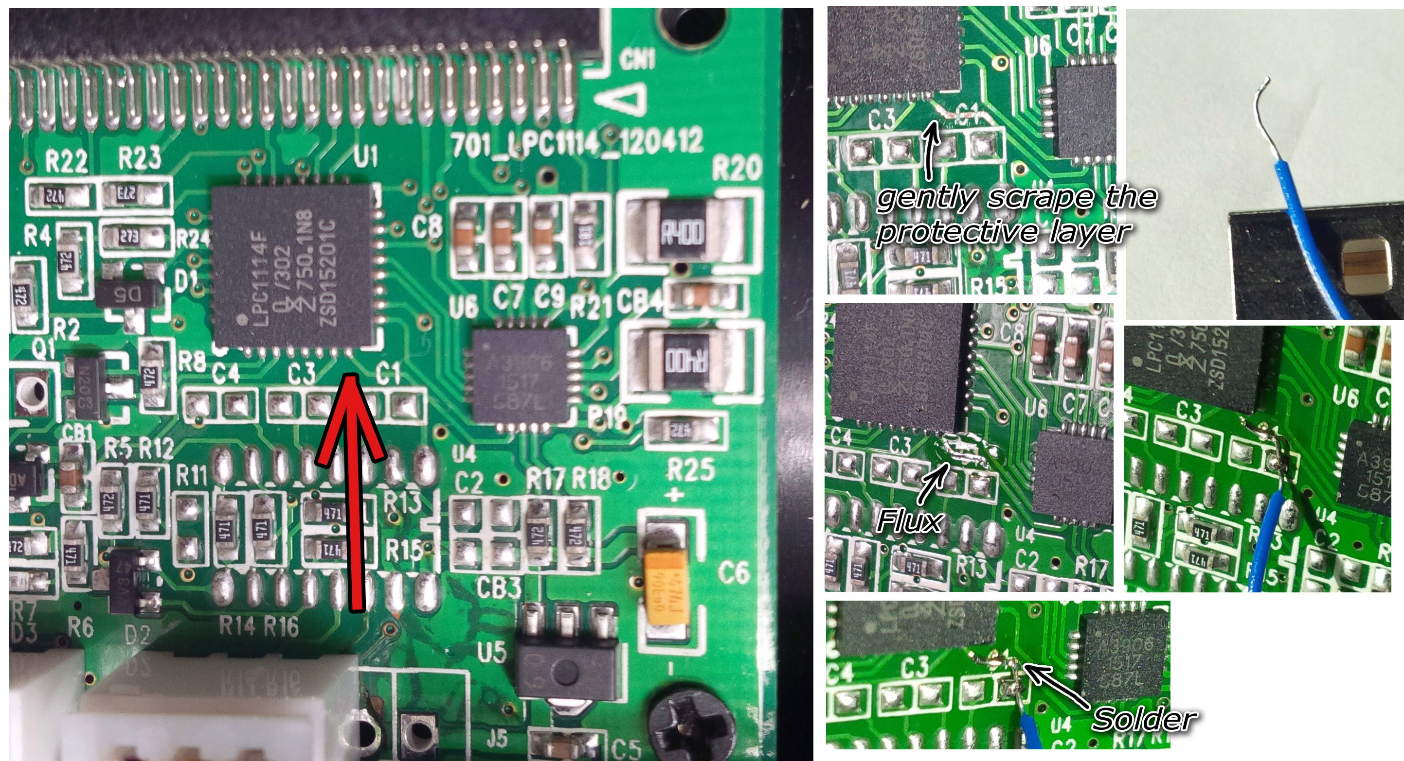
2 - The second step is to have a flow control. For the moment, the only way I found is to solder a wire on a pin of the printer's controller chip to get the line paper advance information. I gently scratch the protective layer of the copper track, and solder a wire there.
![]()
![Printer Board]()
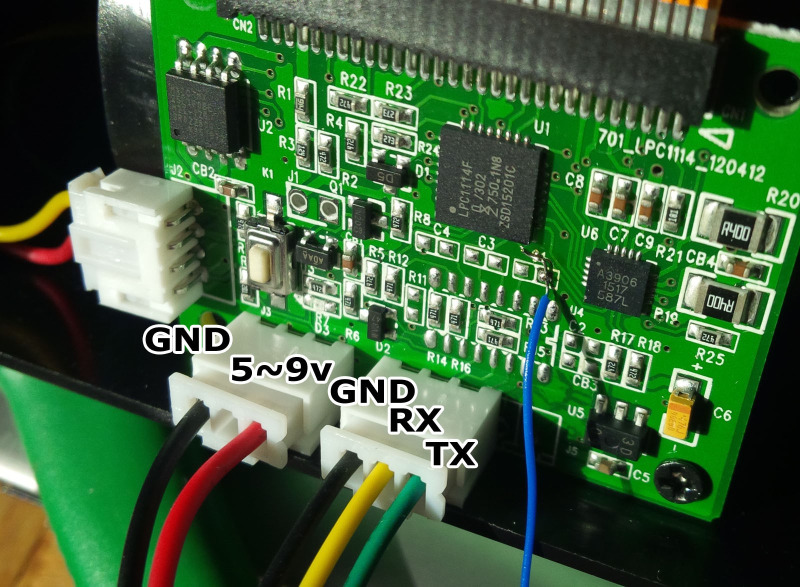
3 - The connections are the following. This little wire from the step motor controller will be connected to the pin15 of the raspberry pi.
![]()
And the printer's RX to the Raspberry pi TX (pin8). Printer's TX is not used.
-
2Step 2
The Raspberry Pi SD card
If the adafruit PiTFT screen is used, all linux software steps are described here : https://learn.adafruit.com/adafruit-pitft-28-inch-resistive-touchscreen-display-raspberry-pi/easy-install
Download the wheezy SD card image and flash-it to the card. Follow the adafruit instruction to install the TFT screen.
Otherwise, if the regular HDMI/video is used, install the regular Raspbian linux : https://www.raspberrypi.org/downloads/raspbian/
-
3Step 3
The raspberry camera module connection is documented in the raspberry pi website : https://www.raspberrypi.org/help/camera-module-setup/
-
4Step 4
In order to see the camera preview on the PiTFT screen, the frame buffer copy program must be build : https://github.com/tasanakorn/rpi-fbcp
Or directly download fbcp : https://www.raspberrypi.org/forums/viewtopic.php?p=445550#p445550
or here on github.
-
5Step 5
The source code of the Java program is on the Git repository : https://github.com/pierre-muth/polapi
The runnable Jar file is in the /jar/ folder. (download polapi.jar)
-
6Step 6
At the first startup, the config utility appear (or by typing sudo raspi-config).
- enable the camera
- disable the console over serial port (otherwise the boot sequence will be printed !)
-
7Step 7
The raspberry pi could be accessed with ssh and files copied with scp (or winscp).
Make the following folders:
/home/pi/Photos (where the picture files will be saved)
/home/pi/polapi
On the last one, put 3 files. The file fbcp (if not executable, use "chmod +x fbcp"). The file polapi.jar. And make a text file "config.txt" which contains configuration information. You can download it directly here on github.
It looks like this : (please keep the order and line numbers)
WELCOME:
Welcome to Polapi.
HEADER:
Taken the #date !
SERIAL:
115200
[...]
The line after the keyword "WELCOME:" is printed at startup. It could be a space character to cancel it.The line after the keyword "HEADER:" is printed after each pictures and the keyword "#date" is replaced by the raspberry pi date. It could be a space character to cancel it.
Note if there is a file named header.txt, it will be used for the header.
Please note that the raspberry pi alone doesn't keep the time running after switched off. You can add an RTC clock to solve this issue, by following this nice Adafuit tutorial.
After "SERIALSPEED:" indicate the baud rate of the printer. If slower than 115200, it might be some artifacts on the prints, due to the pauses made by the printer.
After "BUFFER:" is the number of pixel lines sent in advance before the program make a pause to not overrun the printer buffer.
After "DEALY:" is the length in milliseconds of the pauses within the transmission.
After HEATINGMAXDOT, HEATTIME, HEATINTERVAL, is the printer parameters
After CONTINUOUSDELAY, is the delay between the starts of print process when the button is held pressed, including the print time itself.
After RASPIVID: is the camera program parameters, see raspivid website.
After BUTTONPIN, is the name of the GPIO used for the button, according PI4J library.
After MOTORPIN, is the name of the GPIO used for the printer stepper motor read back, according PI4J library.
After SERIALPORT is the name of the serial port com use for the printer, such as "/dev/ttyAMA0". The "#default" mean the GPIO one (ttyAMA0).
After SMALLFONT is an attempt to use the smaller builtin font of the printer.
After LINECHAR is the number of characters in one line.
-
8Step 8
Via ssh, or at a final stage by editing the /etc/rc.local file, use the following execution sequence :
cd /home/pi/polapi/
./fbcp & (if you have the SPI LCD screen)
sudo java -jar polapi.jar
Discussions
Become a Hackaday.io Member
Create an account to leave a comment. Already have an account? Log In.