t the end of March, (and early april), I was under the impression that I had failed to build a convincing case that it's possible to design a low-cost mobile x-ray system capable of being used for human diagnostics.
At the time, it appeared further research was needed to build a more convincing argument.
So, being a university student at the time, what seemed like an acceptable option was to write a "thesis" of sorts, with a problem statement, research, and detailed designs of some x-ray system components which would be integrated in such a machine. For kicks, I decided to illustrate much of this document, such that it wouldn't be a boring read.
For about a month I worked all night on this, and at the end of may, had something quite detailed, with many illustrations.
For reasons of bandwidth, I can't host the 400Mb file for y'all.
However, here are some fantastic tidbits that are worth sharing!
  _   _                 _
 | | | | _____      __ | |_ ___   __  __     _ __ __ _ _   _
 | |_| |/ _ \ \ /\ / / | __/ _ \  \ \/ /____| '__/ _` | | | |
 |  _  | (_) \ V  V /  | || (_) |  >  <_____| | | (_| | |_| |
 |_| |_|\___/ \_/\_/    \__\___/  /_/\_\    |_|  \__,_|\__, |
                                                       |___/
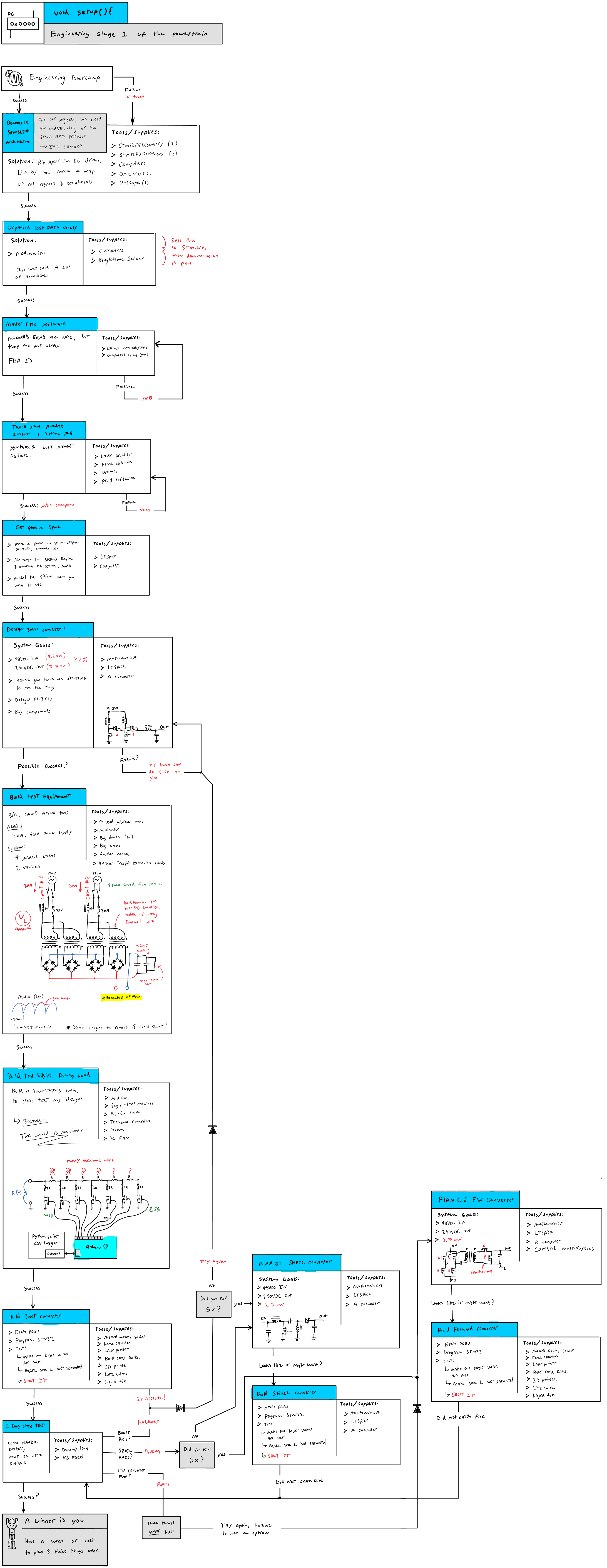
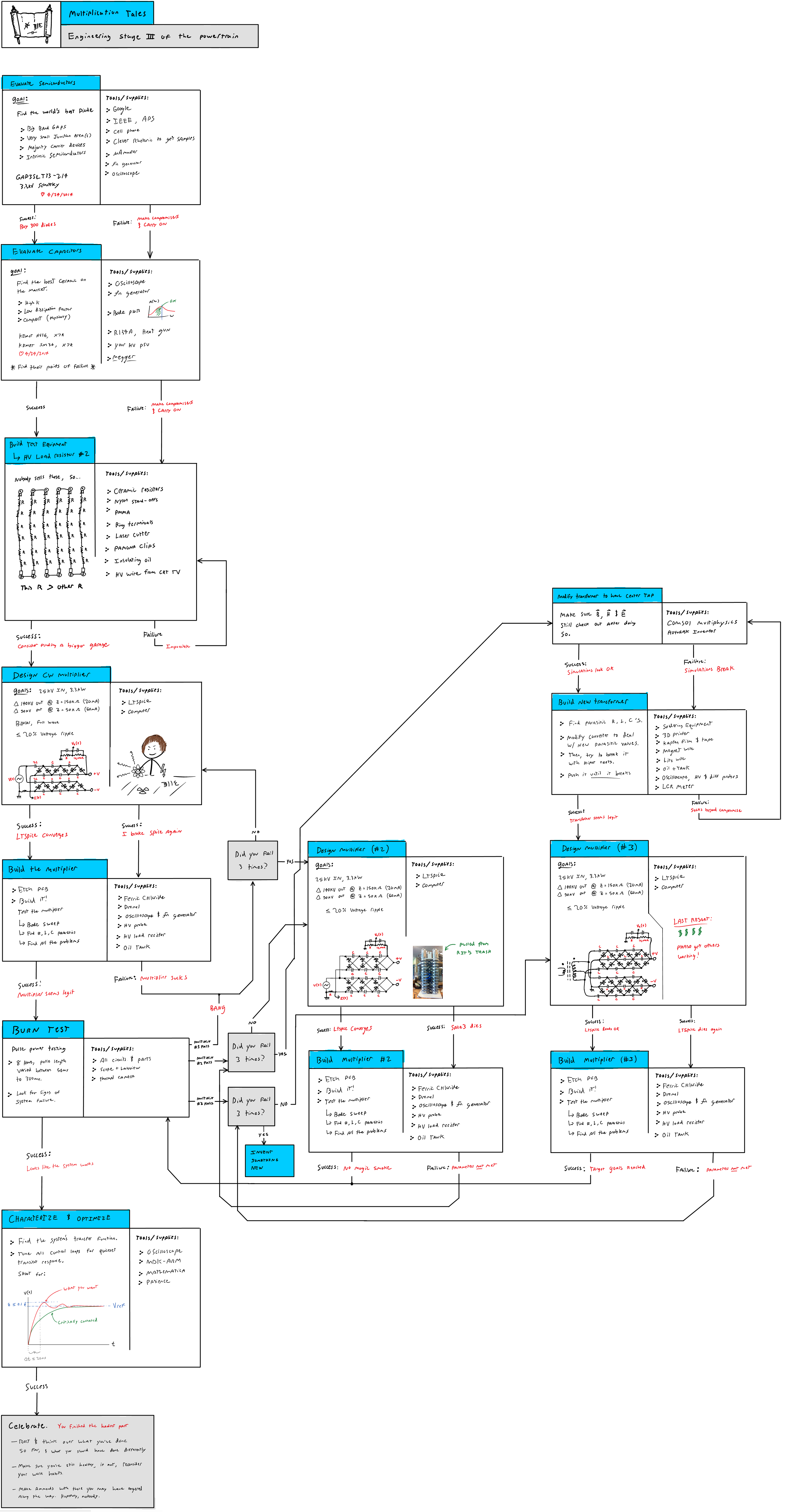
Below is a comic that describes how a project such as this x-ray source would proceed. To some, who have many engineering projects under their belt they may find it a bit humorous (and too true).
-
Step 1: Engineering Stage 1 of the power train
-
Step 2: Engineering stage 2 of the power train

Step 3: Engineering stage 3 of the power train
-
Step 4: Engineering a modern austin ring transformer

-
Step 4: Lithium-ion battery shenanigans

-
Step 5: Digital controls design

-
Step 6: X-ray dosimetry

-
Step 7: Prototyping an x-ray tube designed for this purpose

-
  _       _   _           _                 _
 (_)___  | |_| |__   __ _| |_   _ __   ___ | |_
 | / __| | __| '_ \ / _` | __| | '_ \ / _ \| __|
 | \__ \ | |_| | | | (_| | |_  | | | | (_) | |_
 |_|___/  \__|_| |_|\__,_|\__| |_| |_|\___/ \__|_
   __ ___      _____  ___  ___  _ __ ___   __|__ \
  / _` \ \ /\ / / _ \/ __|/ _ \| '_ ` _ \ / _ \/ /
 | (_| |\ V  V /  __/\__ \ (_) | | | | | |  __/_|
  \__,_| \_/\_/ \___||___/\___/|_| |_| |_|\___(_)
Along with LOLrioKart speeding past the ivory tower, some parts of this are worth explaining further.
-
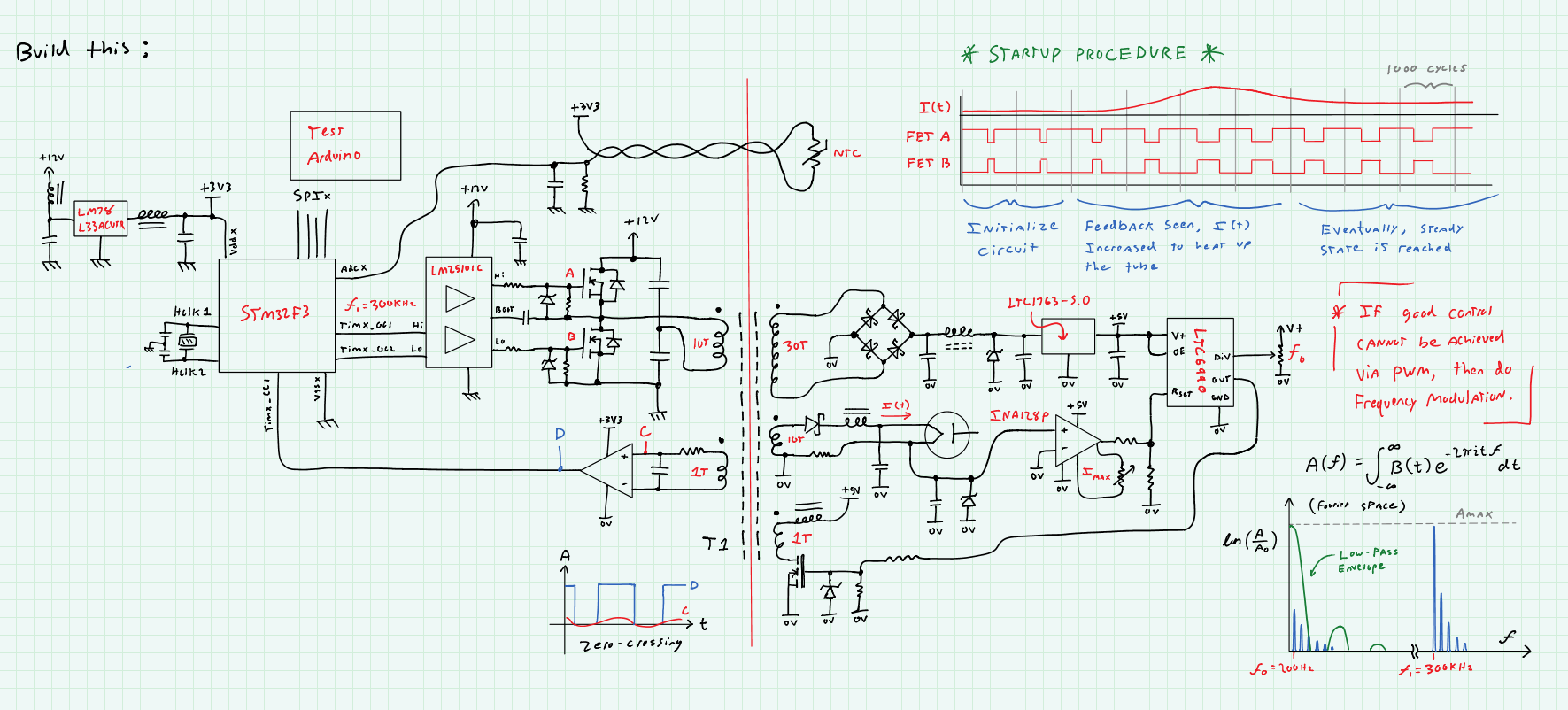
Austin ring transformer:
When operating an x-ray tube, it's often the case that you do so in a manner that is "center grounded" so to speak. The anode receives +V, the cathode -V, and, any insulation used only needs to withstand V, and not 2V.
Unfortunately, this means you must provide an isolated 3V source for the tube's heated cathode, which must withstand -V plus some safety margin. Typically this is done with an "austin ring" transformer, but those are big and heavy, so, this is my switch-mode replacement. :-D
-
High voltage source:
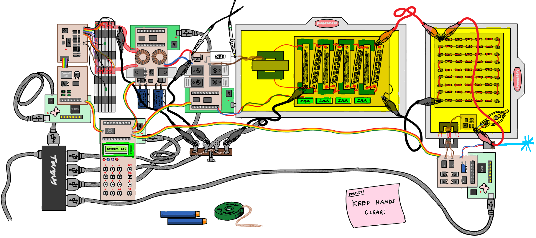
This would be the switch mode power supply topology used inside the x-ray source. It consists of a lithium ion battery stack, boosted to a few hundred volts by a polyphase boost converter, then boosted further using a series-resonant H bridge inverter. Note, the CDE capacitor in series with the H bridge's load, is chosen such that it cancels out the transformer's leakage indutctance, and provides an overall lower impedance for the power supply.
This is then fed into a voltage multiplier, which provides the extreme potentials needed for the x-ray tube.
-
But, after showing this work to many folks in Rochester, NY, I soon realized that I wasn't going to get very far there. Despite being a healthcare powerhouse, ROC isn't quite the right place for people to talk about hardware technology, especially so, given Kodak and Xerox are both on their way out.
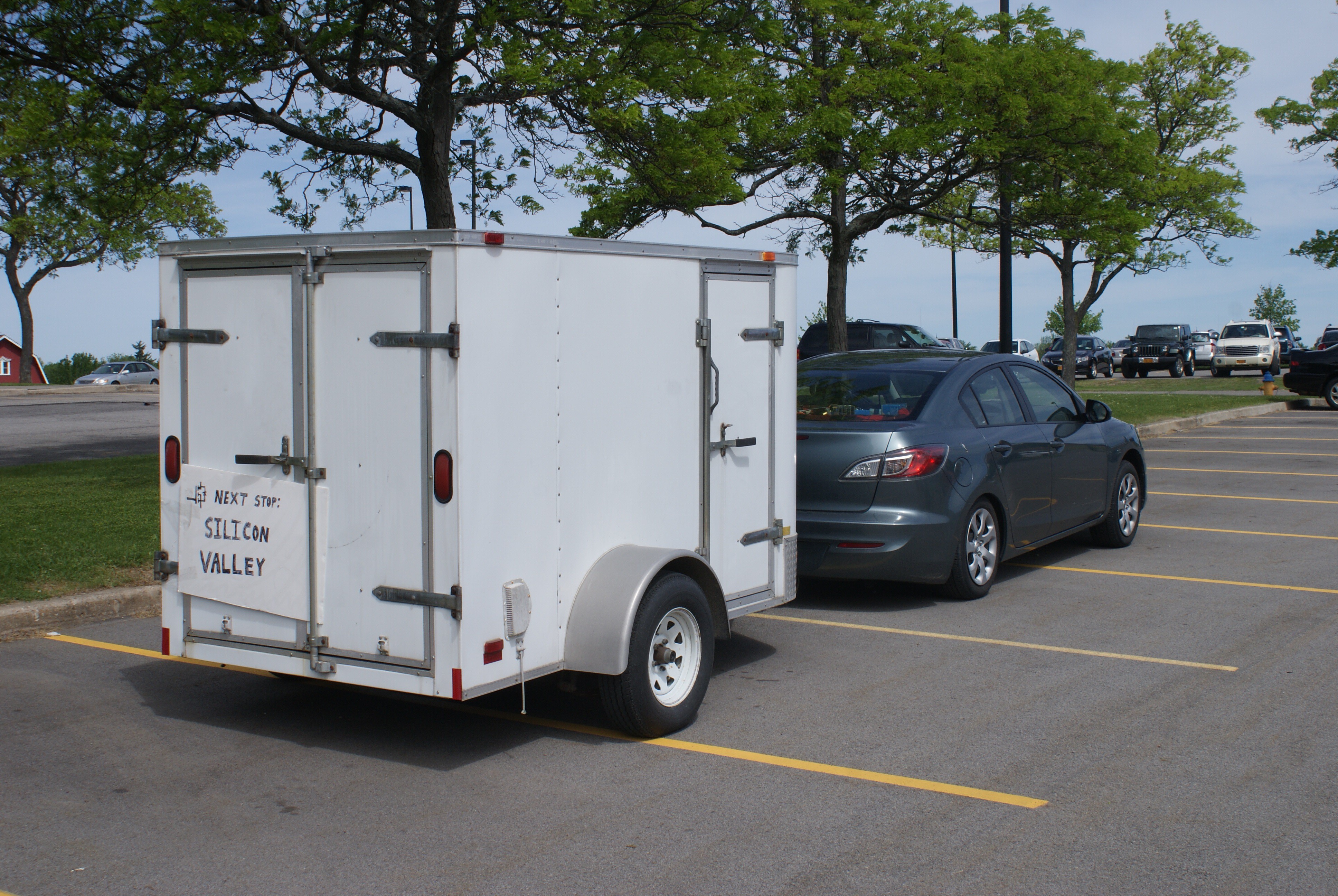
So... I dropped out of university, and bought a trailer.
 Adam Munich
Discussions
Become a Hackaday.io Member
Create an account to leave a comment. Already have an account? Log In.