Adam Munich
-
September 2015 - Soft 'No's, CT Scanners, & Bootstrapping
09/29/2015 at 22:16 • 2 commentsSeptember has been a busy month. Tyler and I have moved from the east bay to San Mateo in search of more space to do our work in!
However while that was successful, this month has been filled with more rejection from potential financiers for this project. The VC world is very funny, no one ever says "no", but, instead they say "come back later", "now's not the time", or some variant thereof. Chiefly, it appears that manufacturing for most investors doesn't seem to be an exciting opportunity, and, as we add up the overhead costs it's easy to see why. For most low-ticket items, it's just barely worth it in America, and this is unlikely to change any time soon.
-
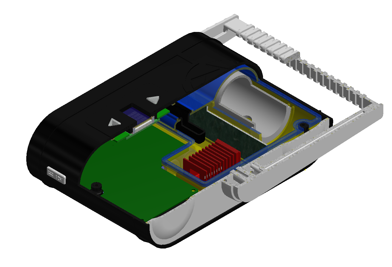
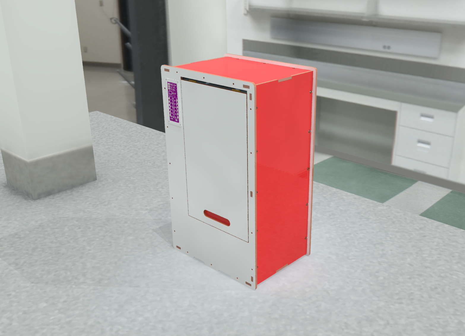
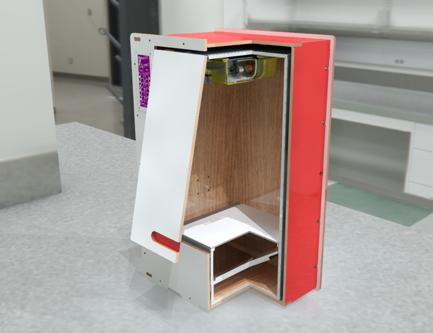
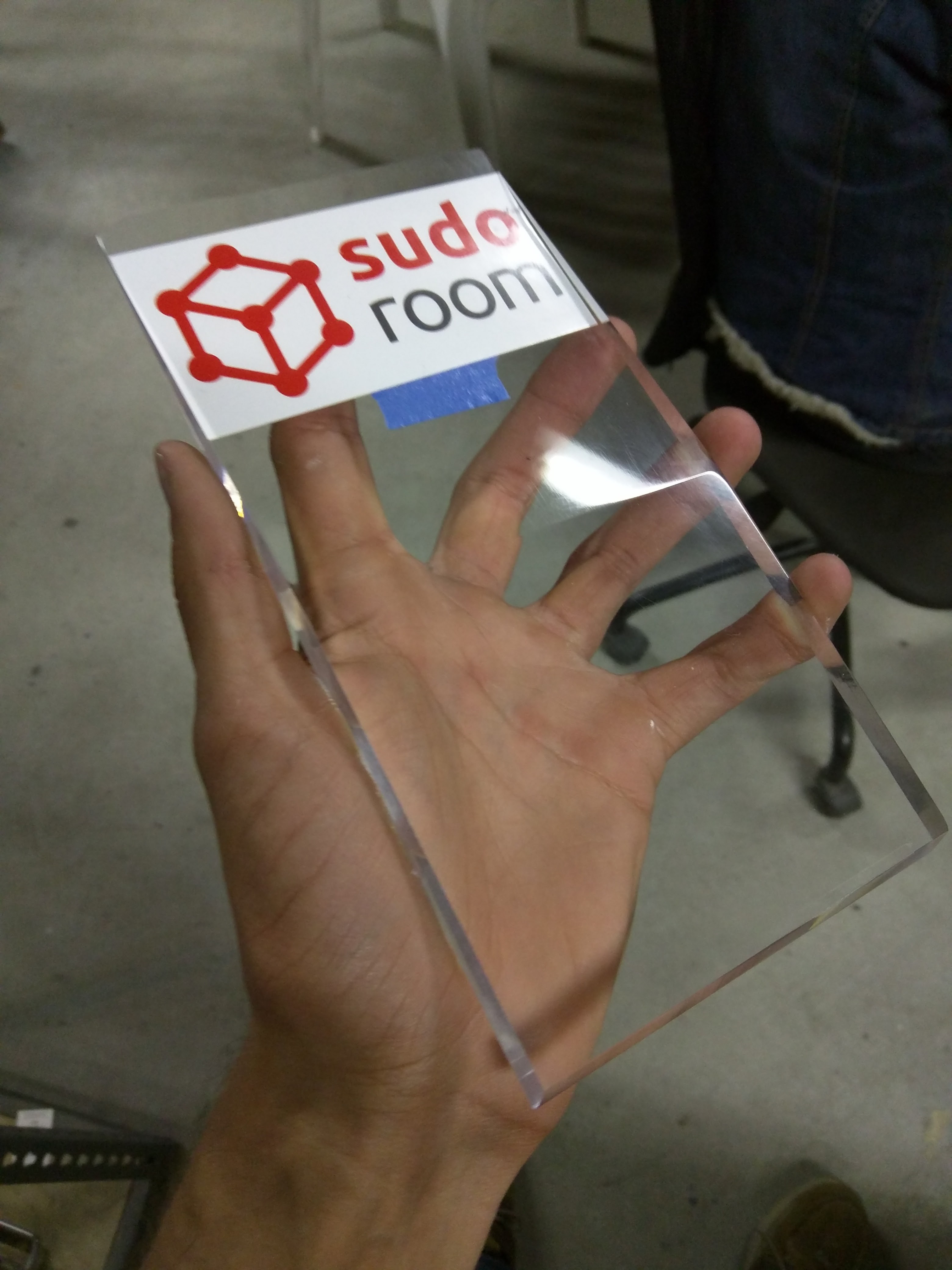
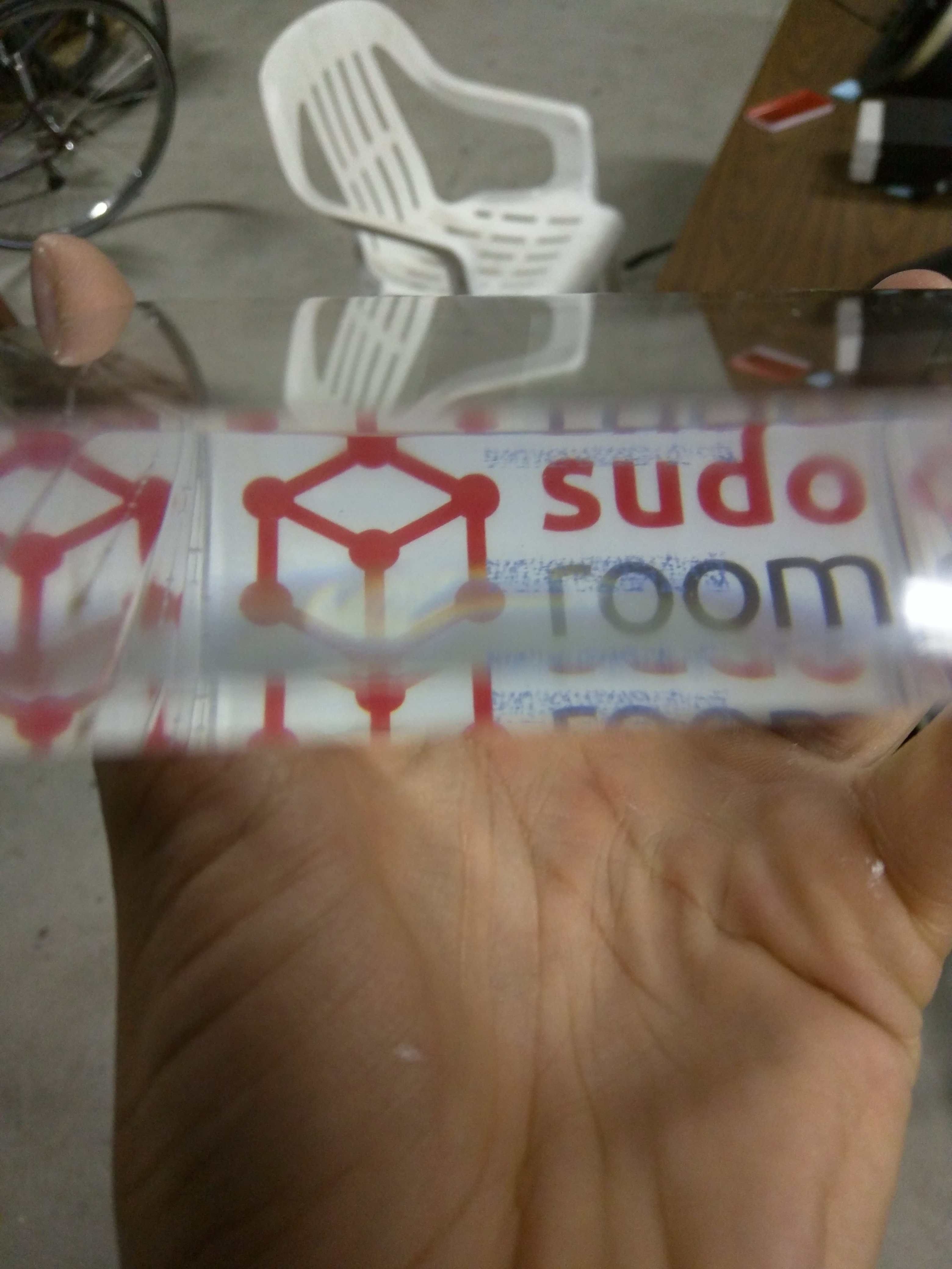
Given this frustrating situation, we've decided that it's worth attempting to bootstrap our work by designing an x-ray scanner usable by makers. Particularly, a desktop CT scanner! Much of this month has been spent designing this scanner, in a manner to be as affordable as possible, and, writing code to handle the cone-beam back-projection, and CV functions to interpolate the sparse-ly sampled data.
-
![]()
![]()
-
This scanner uses a simpler x-ray source, which is no more than a transformer, fancy plastic, an H bridge and ATMEGA-32. It's not yet complete however, and so, we have few useful designs to share.
Mainboard: https://drive.google.com/file/d/0BwIWrZZX8IW6eWl2d1JYcFYzQm8/view?usp=sharing
HV PCB: https://drive.google.com/file/d/0BwIWrZZX8IW6ajVUQlVQcGJPNWc/view?usp=sharing
However, if you'd like the partially-completed CAD models, feel free to say so!
-
![]()
-
-
July 2015 - A big collection of x-ray photos for y'all
08/16/2015 at 03:00 • 2 commentsIn this log I'm going to share a big collection of x-ray photos for y'all.
Many of these photos were built from multiple x-ray exposures on a small sensor, and have been stitched together into the result you see. As such, please forgive any discontinuities there may be in the resulting images.
Also, they have been compressed. Many of these images started off as huge PNG's: too big to share all willy-nilly.
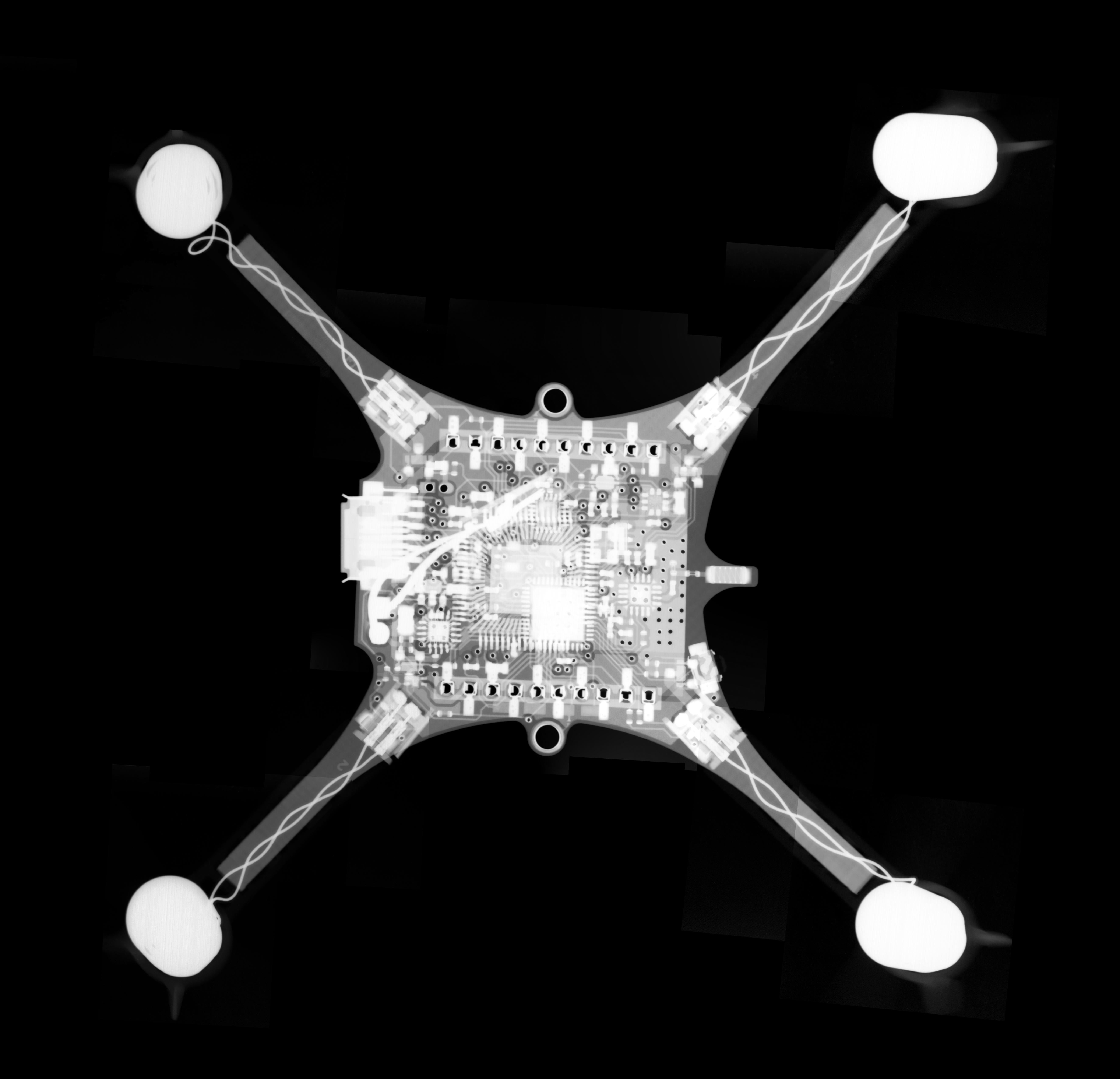
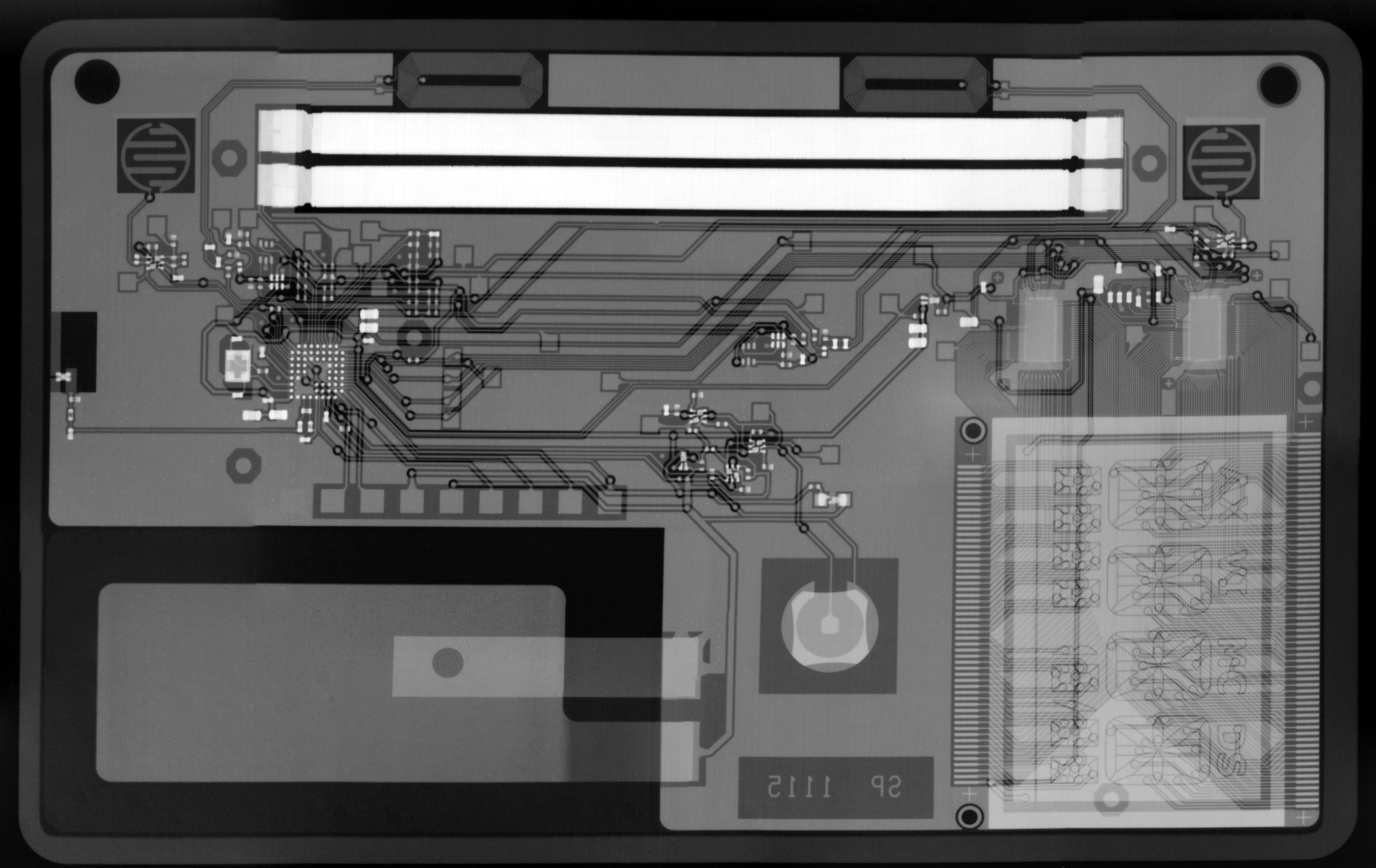
Crazyflie 2.0
![]()
Coin electronic credit card:
![]()
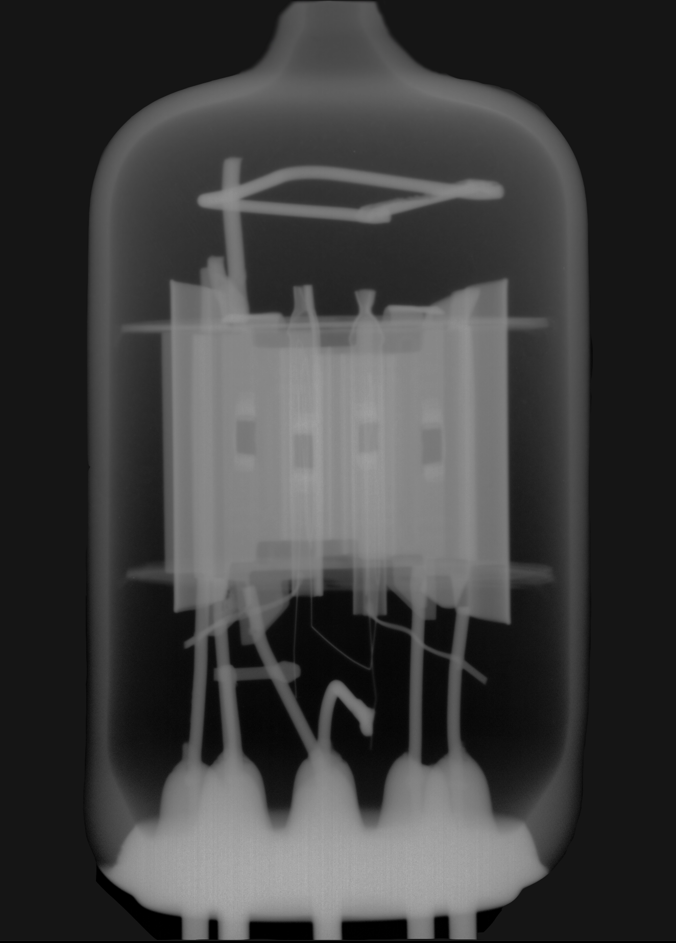
Small vacuum tube:
![]()
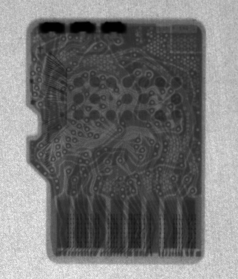
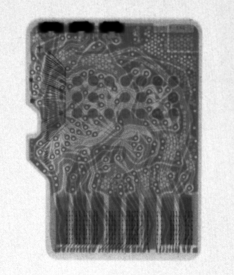
Micro SD Card:
![]()
Rotational x-ray of pololu motor driver:
![]()
Rotational x-ray of Teensy:
![]()
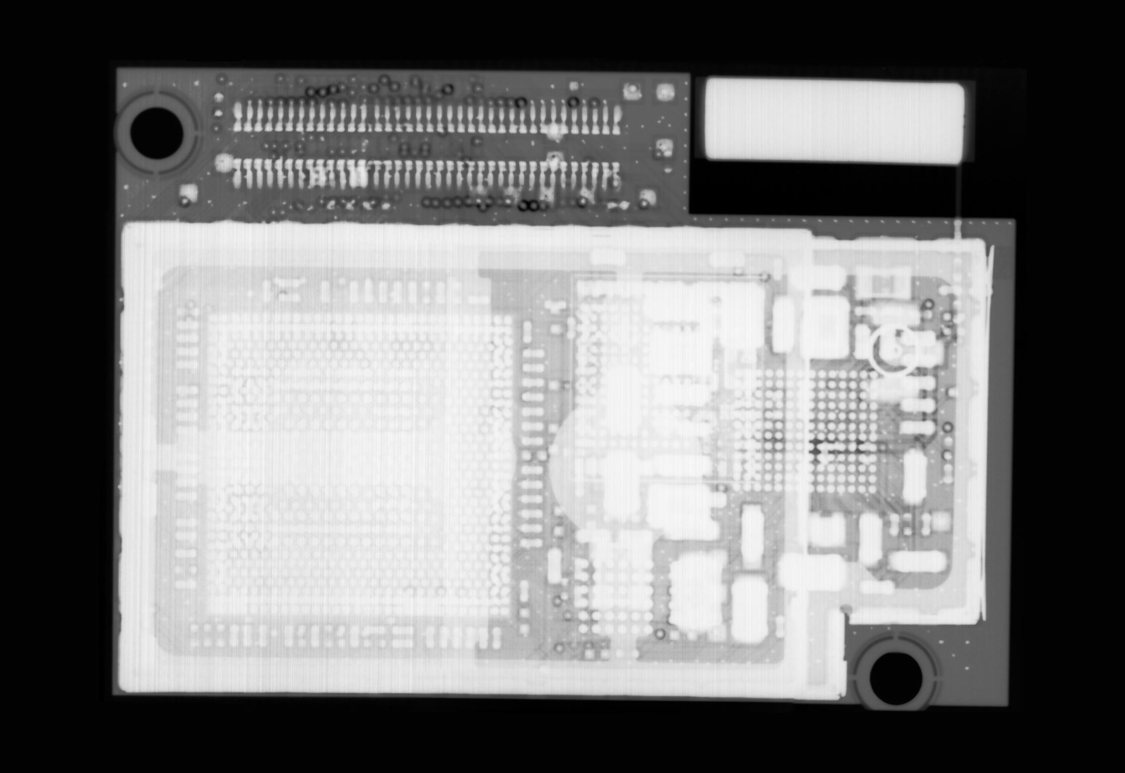
Intel Edison:
![]()
-
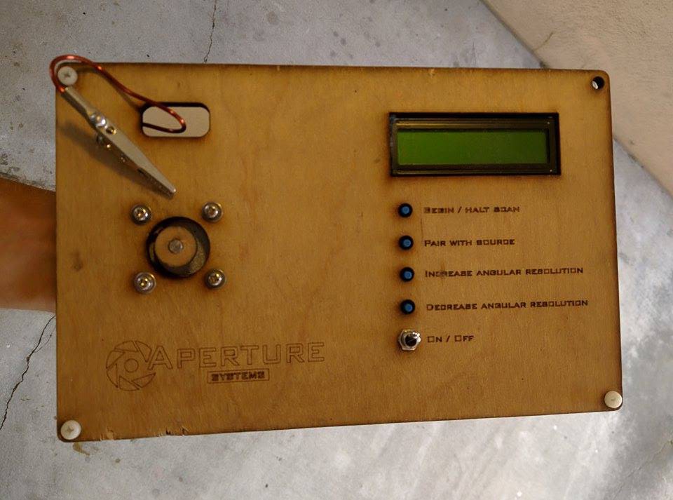
March 2015 - Building a mini "CT scanner" for fun
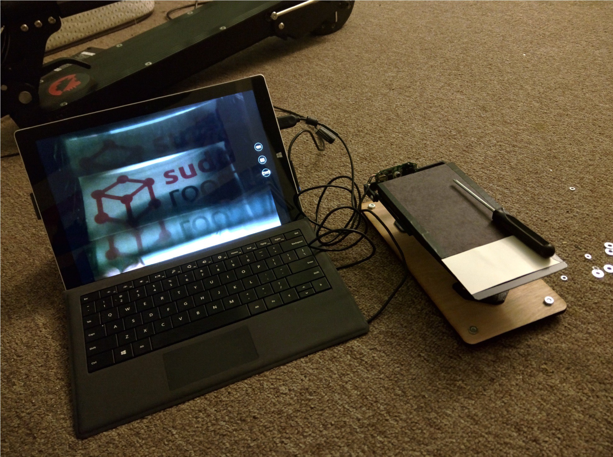
08/16/2015 at 02:49 • 1 commentWith a working, mini x-ray sensor, and a bluetooth-controlled mobile x-ray source on hand, it seemed silly not to capture some 3D / rotated x-ray images of the small electronics trinkets I could get my hands on.
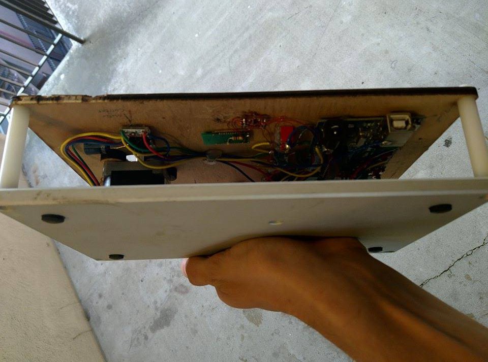
To do so, I put together a small stepper motor system consisting of a micro controller, a stepper motor driver, a few buttons and a nice base. The microcontroller is programmed to accept some integer number of steps, and will send commands over its serial port to the computer before each step.
-
![]()
![]()
-
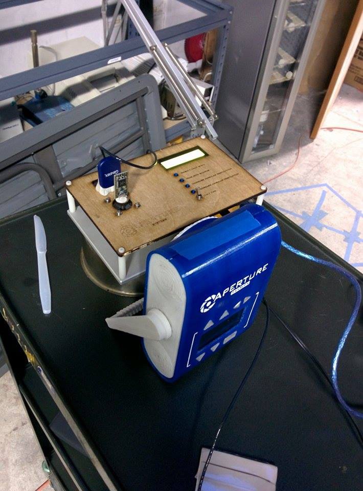
On my computer, I bridged the serial port to feed its incoming data out the virtual bluetooth port, connected to the x-ray source. Initially I had a bluetooth radio on the CT scanner itself, but, it proved too unreliable for reasons I haven't yet figured out myself.
-
![]()
-
The results were pretty to look at, to say the least.
I have not yet written a script that preforms the radon transform on the image collections, but, if anyone is willing to take the challenge, I'd love to hear more about it!
Pololu Stepper driver:
![]()
Teensy 3.0:
![]()
-
The source files for this small CT scanner are available here. It uses a standard size stepper motor.
-
August 2015 - Open sourcing a year's worth of development, and hoping HAD thinks we're awesome
08/15/2015 at 22:43 • 0 comments![]()
-
Without many folks interested in helping us build better x-ray hardware, we're turning to my favorite blog for support.
Despite being adept hackers, to take our projects from "that's cool and kind of works" to, "we can make a bunch of those for WHO" will require experiments, tooled molds and other things that are a bit out of our chicken-strips budget.
We're going to open-source our development, inventions, and hope that the community and judges find our mission worthwhile, and our work impressive enough to support.
-
![]()
![]()
Without further adieu, here's everything that can be built at home.
-
Parts list for the 200W source: http://i.imgur.com/LYPxxfI.png
Board file for the 200W source: https://drive.google.com/file/d/0BwIWrZZX8IW6U2trR2JNYU9ZRzA/view
Cad model for the 200W source (Rev 1): https://drive.google.com/folderview?id=0BwIWrZZX8IW6fldCRFpucXJuakRndlJ1QVZWRlNqX3IxdVFIVkJlNTdFQk1lVmhzZy1VeEk&usp=sharing
Cad model for the 200W source (Rev 2): https://drive.google.com/folderview?id=0BwIWrZZX8IW6fk5BVy1TMmd6YW9wSk9hU3RaT1pmd01mTHRueXhRX1BfbEdHUmxlb2stR1U&usp=sharing
Code for the 200W source (Rev 1): https://drive.google.com/folderview?id=0BwIWrZZX8IW6flpXNkozWVl1QzNReW9jS3B4UDdmNV9yNlg1ZTh6WWlhMTJRRlo4QWxFeUk&usp=sharing
Code for the 200W source (Rev 2): https://drive.google.com/folderview?id=0BwIWrZZX8IW6fll5U1U5ekF6cmNOWV8yVElYMlRqcC1xdmxqMWJ2N3NIMVVqbGRmSHRNbE0&usp=sharing
Code for the photostimulable phosphor sensor: https://drive.google.com/a/adammunich.com/folderview?id=0BwIWrZZX8IW6fk4zTXN2Smx2WTVYTzU1RnBSZ3Y1emE1YXdod1NJcHZLQi1WOW1HSHVPZHM&usp=sharing
CAD model for the sensor prism: https://drive.google.com/a/adammunich.com/file/d/0BwIWrZZX8IW6VTJNQ2h1Q2UtaGM/view?usp=sharing
CT scanner source files: https://drive.google.com/folderview?id=0BwIWrZZX8IW6fjF3LXdmUzlzMUUwWHhiS3VDcDkwV2dTTUttRFFnb1hDMENnYzhiV3JFNkU&usp=sharing
-
June, July 2015 - A friend joins, no's from google.org and other fun activities
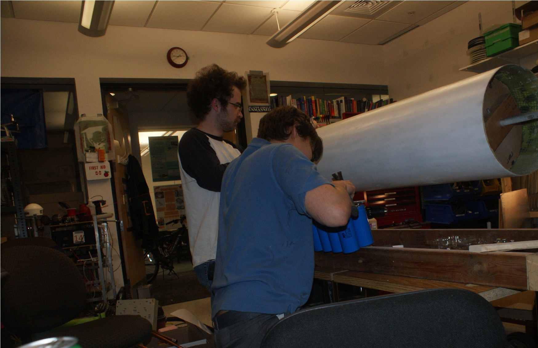
08/15/2015 at 21:44 • 0 commentsAt the beginning of June, Tyler "Frodo" haun moved to CA with a sleeping bag, to join his long-time friend hell-bent on the mission to build cheap x-ray systems.
-
![]()
-
I don't blame him; buffalo isn't quite the hotbed for technology!
Tyler's main interests are computer programming and signal processing, and, with a doublet of engineers on this project it was time to go look for people to help make it happen.
-
Google.org - Uninterested
WHO - Sounds good, come back when you have products ready
NGOs who distribute med devices - Sounds good, come back when you have products ready
Gates Foundation - No response
Sand Hill Road - "Soft No's"
Hanergy - No response
(continued...)
-
Or should I say... didn't care too much.
Is anybody out there?
![]()
At mid-July, Tyler took a job debugging code to upgrade from ramen noodles to chicken strips, and I continued polishing up some of the work we had to share with the hope of finding some sort of path forward.
-
April, May 2015 - Designing a low cost x-ray sensor - second attempt
08/15/2015 at 21:19 • 0 commentsBuilding upon what I learned from the last sensor, I set out again to build a low cost x-ray camera. This time, I excluded the possibility of using any moving parts in the design.
After thinking about flat panel displays, I hypothesized the following:
![]()
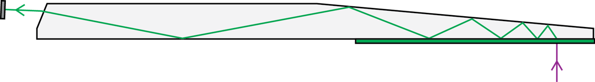
Following the total internal reflection principles used in LCD backlight panels, is it possible to capture an image in the same way? That is, to design a prism which folds light coming in at the critical angle, throughout the prism body in such a way that you see the image of its face in the base of the prism.
If so, I could capture the image on an x-ray phosphor panel with little more than a camera and molded plastic!
-
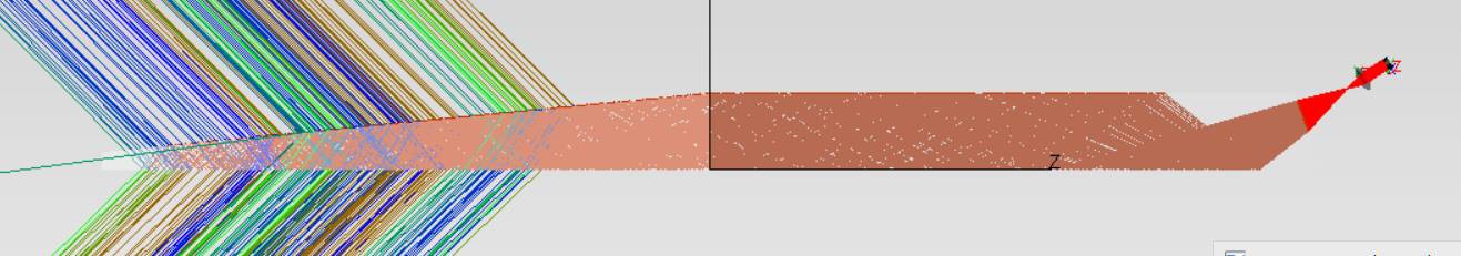
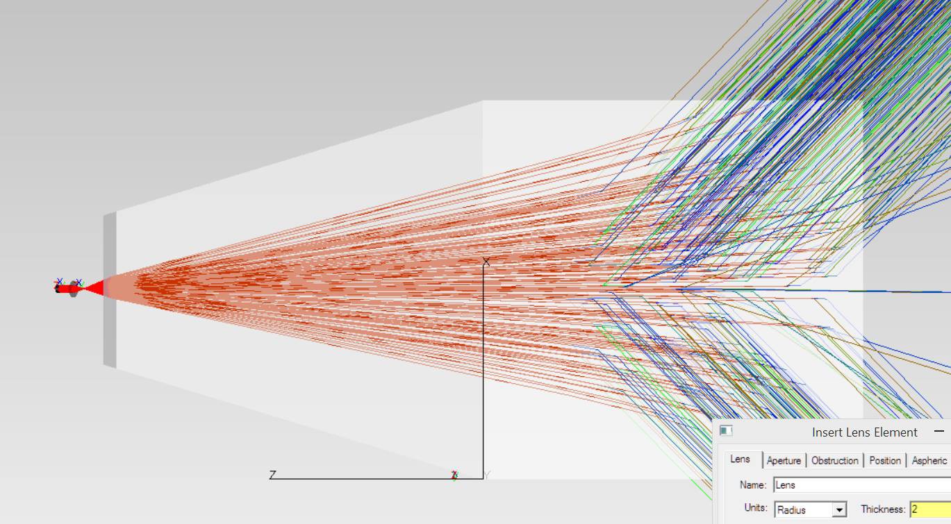
Within a few days, I had learned how to use optical design software. In theory, my models suggested that this could work.
![]()
![]()
-
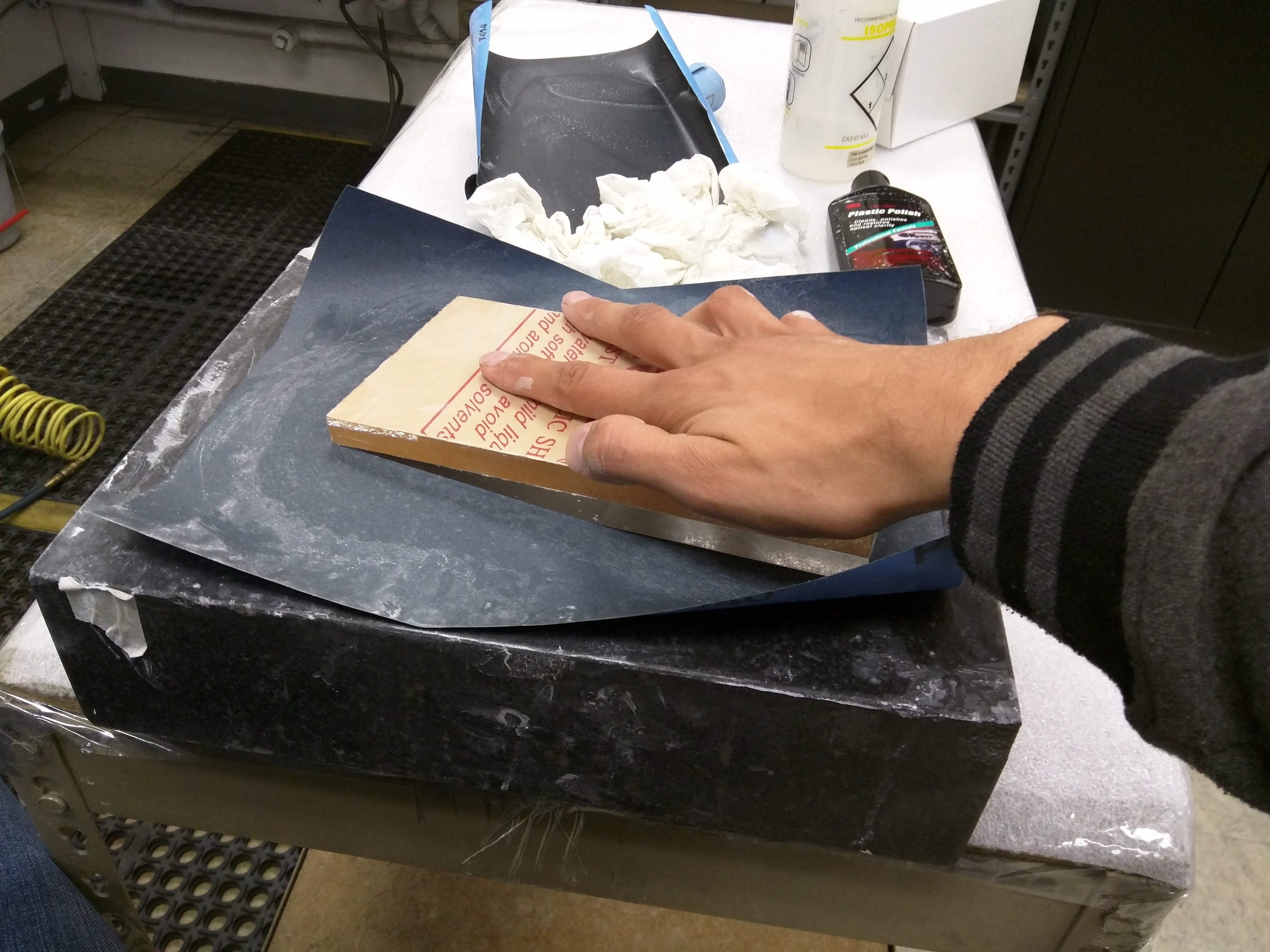
But how could I possibly test this in the real world? I never had optically polished anything before, let alone built a prism.
The answer is, very carefully.
-
-![]()
And slowly. This took a few days.
Eventually, I had my prism.
-
![]()
-
And my lord, it worked.
-
-![]()
With this, a phosphor plate and a camera with large pixels, I should be able to capture x-ray images without film, for a substantially less sum than if I were to make a large silicon wafer for the purpose.
To test this, I made the prism light-tight, and coupled (the same crappy) webcam to it..
-
![]()
-
And in 200 ms, I had a reasonable x-ray image! I had matched x-ray film in exposure dose.
-
![]() -
-The image is a bit blurry as my optical surfaces were a little less than stellar, but with a diamond turned mold for the PMMA, this is won't be a problem!
-
March 2015 - Designing a low cost x-ray sensor - first attempt
08/15/2015 at 20:33 • 0 commentsAt this point, I had recovered, or rebuilt most of what was lost in February. Feeling (somewhat) better, I set out to design a low cost x-ray sensor to accompany the x-ray source. Film after all, is expensive, messy, and, very logistically troublesome for medical practices in places that have less infrastructure than the USA.
-
![]() -
-Silicon wafers are expensive, let's use less of them!
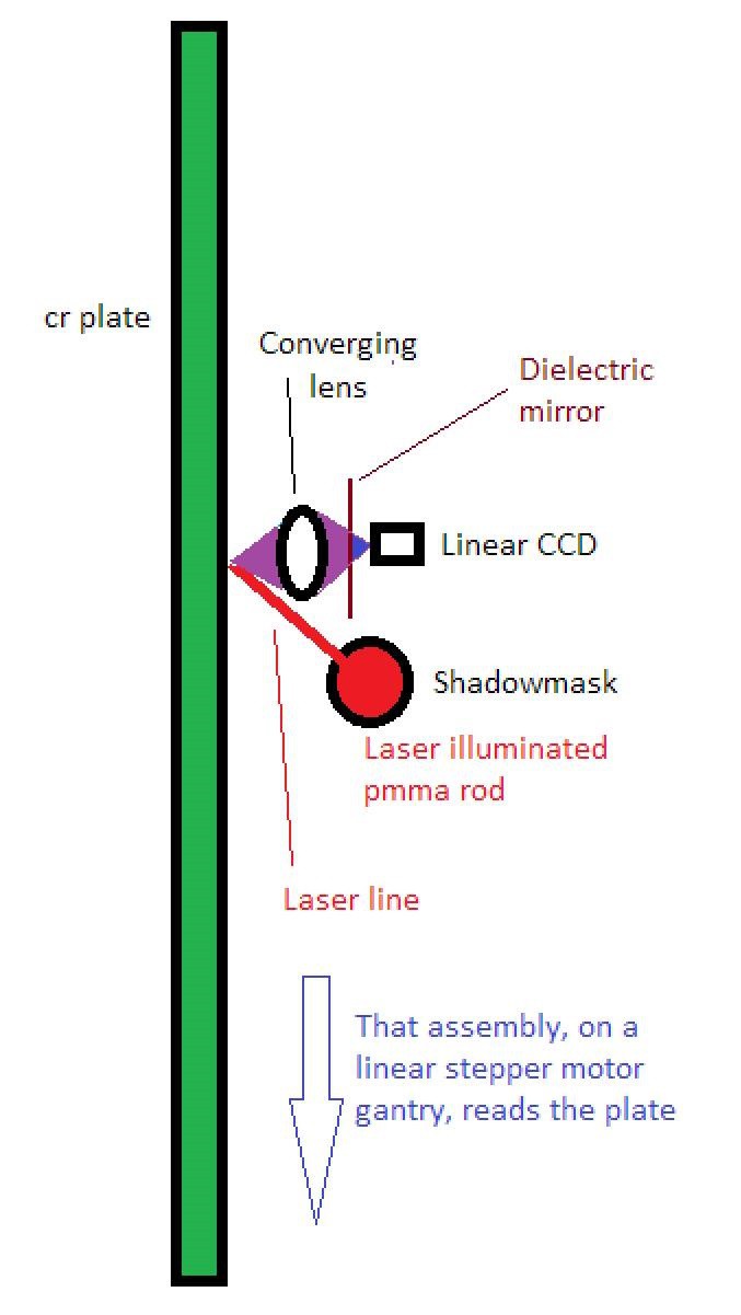
By using a photostimulable phosphor plate, (ie, a phosphor whose previously stored energy may be released by a low-energy photon), we
could in theory, capture a low-dose transmission x-ray, and there-after read it out using an array of 650nm laser diodes linearly focused onto the plate with a cylindrical lens, and a 1D array of CMOS photodiodes which sense the stimulated emission (blue light) via a1D-array of rod lenses and a dielectric, high-pass mirror.The gantry containing these optics could be placed behind the plate and moved with a stepper motor much like a flatbed scanner, which would allow us to produce self-contained digital x-ray sensors of any size, at a fraction of the cost of using a 2D array of CMOS photodiodes as is done currently.
To build this, I used;
- 10 Laser Diodes
- Europium-doped barium fluorobromide phosphor
- A floppy disk drive
- A logitech webcam
- Plastic rods and optical cement
- An MSP430 and stepper motor drivers
- Dielectric mirrors from a projector
- Solder
- A cardboard box
- An image intensifier (since the webcam is crappy)
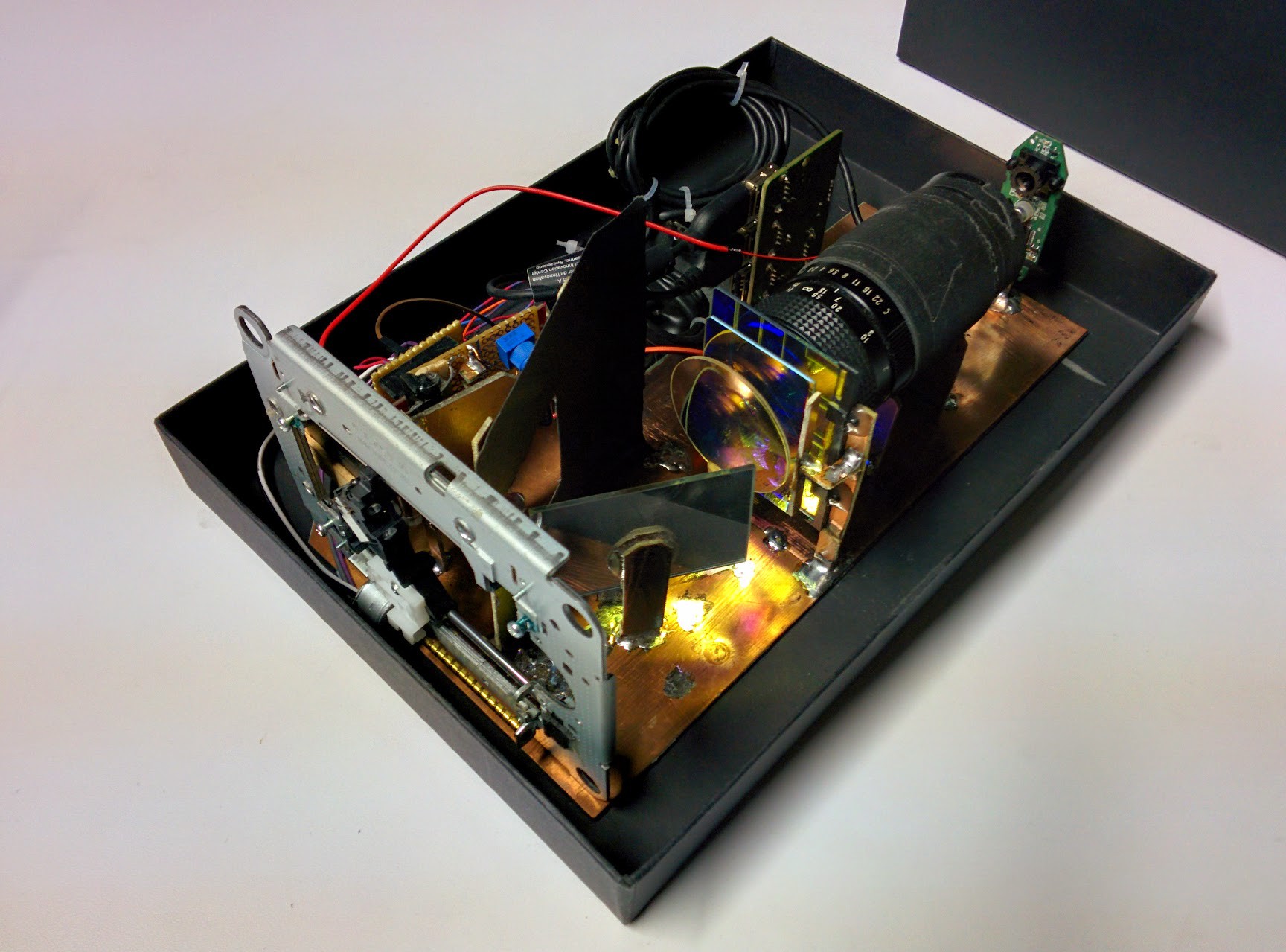
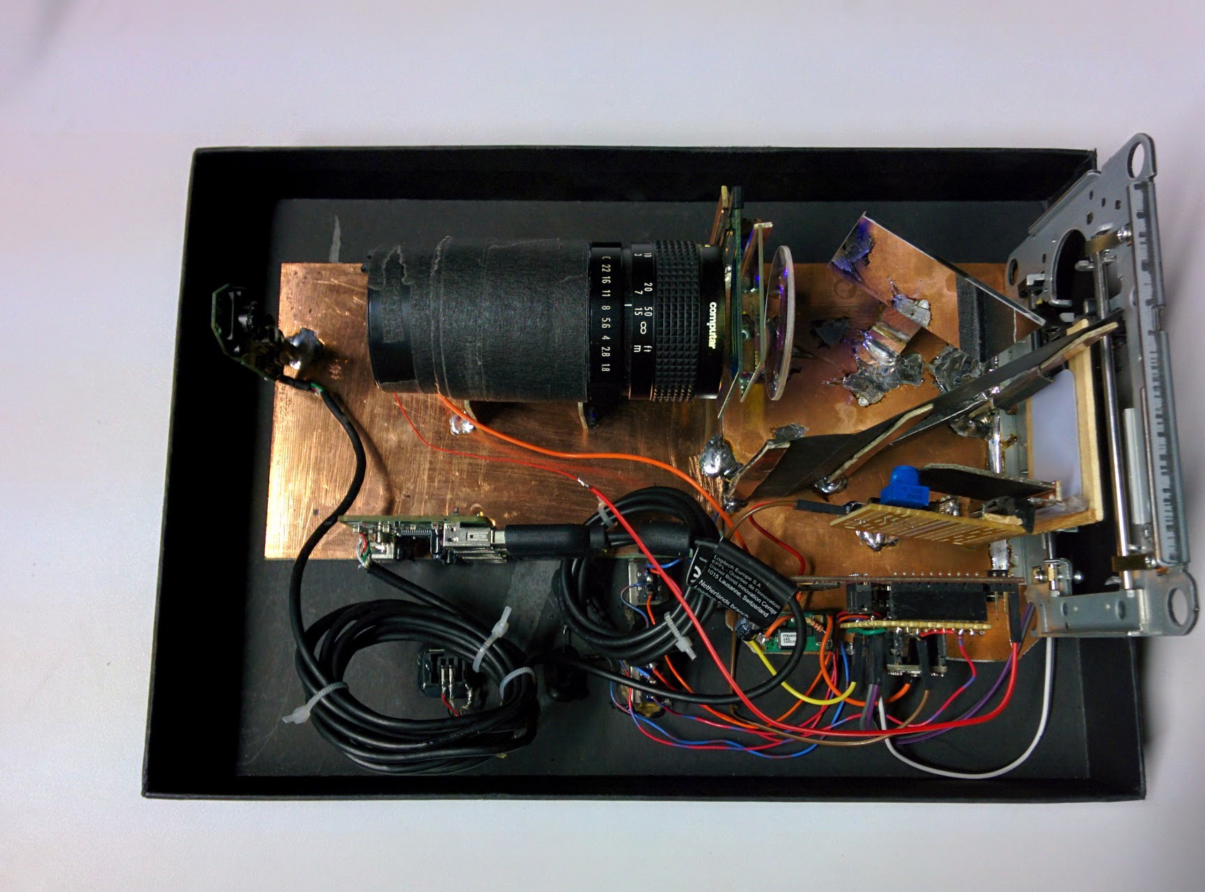
And, built this assembly below:
-
![]()
![]()
-
Before an x-ray exposure, the laser diodes (on the board with the blue potentiometer) would illuminate and cast a line on the phosphor plate, which scans back and forth a few times to clear any cosmic ray noise that could have been there.
After an x-ray exposure, the laser diodes pulse briefly, and the phosphor emits a blue light that is reflected off a mirror, focused through two dielectric filters onto the image intensifier, and then finally digitized by the camera. This process repeats 130 times, and a collection of 1D images are recorded in a computer by a python script for later stitching.
-
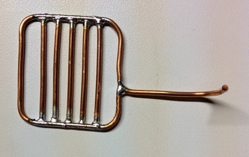
For testing purposes, I built a small copper grille to take an image of.
![]()
-
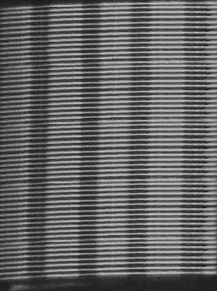
And, this was the result.
-
![]()
-
I wasn't too impressed. Never mind the limited lines / mm. That could be fixed.
What was unsettling, was the terrible dynamic range. Despite the two filters, ted light overpowered blue, To fix this, I would need very expensive, tuned laser diodes and a very narrow band filter to record *only* blue light. This would make the cost of a real sensor prohibitively high.
-
February 2015 - Losing everything in a burglary, fighting depression, and staring into an abyss
08/15/2015 at 19:30 • 0 commentsAt the end of January, I had built something incredible. A 200 watt, backpack x-ray source, and accessories, capable of taking 80 exposures on a battery charge, and with a beam resolution great enough to see the bond wires in an IC.
How amazing!
-
![]()
![]()
-
On February 2, after working 14 hour days, for 4 months straight, it was time to take a break. I backed up my files on a hard drive, an SD card, and a CD, put everything in a box, and drove to the YMCA for an evening of rest.
When I came back, I was greeted with a smashed automobile, and glass scattered about the parking lot. The box was gone, my computer was gone. Even the flash drive in the center console.
I lost all my work.
Everything.
I go home, and go to sleep.
The next day, I surveyed the damage to see what could be recovered.
Unfortunately, not a whole lot. My online backups were 2 months old, I had no cad models saved, no circuit designs, no documents... nothing. In haste, I printed up posters, and taped them all over Oakland. Maybe someone would spot the machine? Maybe...?
At this point, I wasn't feeling the best. "There is so much work that needs to be done now", was all I could think about. In fervor, I spent 2 sleepless weeks rebuilding everything from memory.
A new cad model. New code. New PCBs, New everything.
-
![]()
-
But, life just kept getting darker. Eventually, I set everything aside and just... thought.
It started to set in, that perhaps I was going about life wrong. If I could put 120% into something, and have nothing become of it, what's the point? Why bother?
We all know money doesn't bring happiness. Work doesn't make people happy. Even accomplishment only brings about fleeting jubilance.
What brings profound joy is people. The time you spend with them, how you spend it with them, and the memories and relationships you build with them.
Some of the most fond memories I had were of the time I spent with people, not just with electronics.
-
![]()
-
I set down my soldering iron, and played the bass guitar with some folks at Sudo Room.
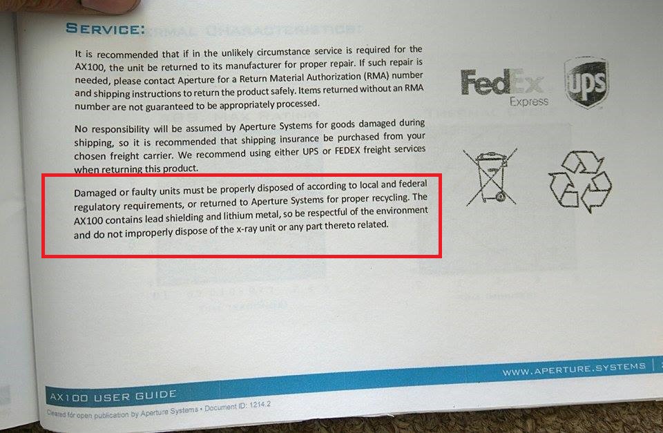
At the end of February, I received an email.
-
![]()
-
An old man at a nursing home wants to return the x-ray machine for recycling. Perhaps that user manual wasn't a waste of time after all.
You just can't make this shit up.
-
January 2015 - Wrapping up the prototype and repairing bond wires by hand
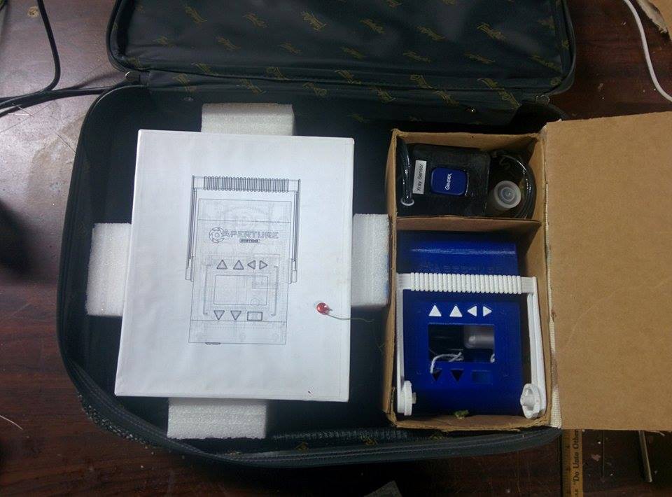
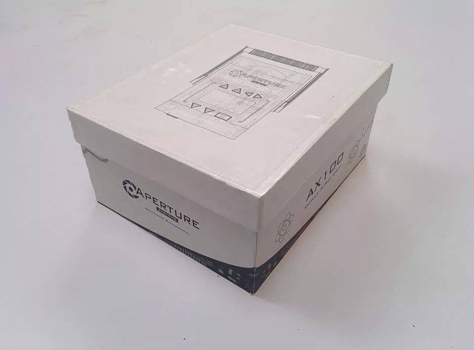
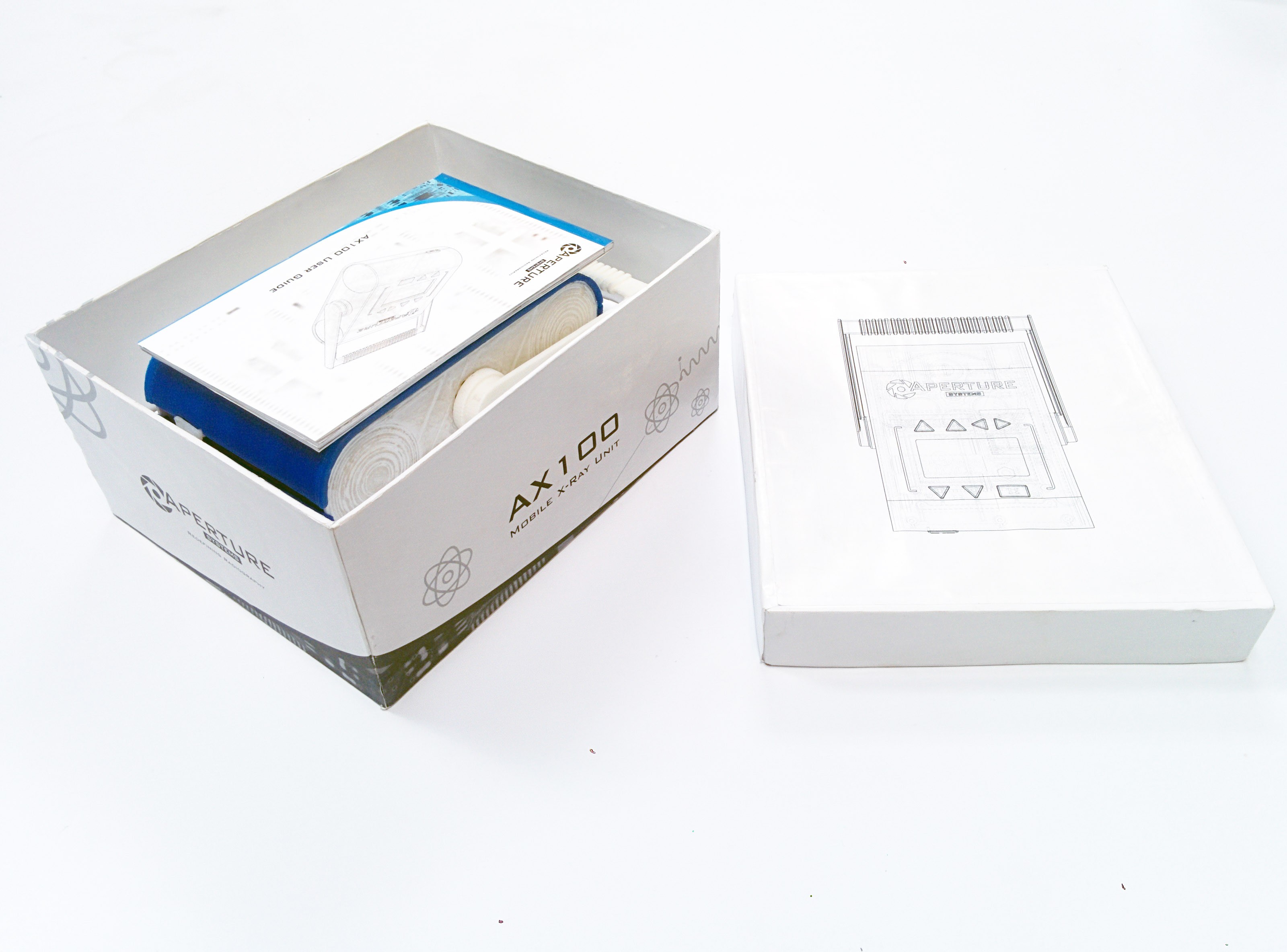
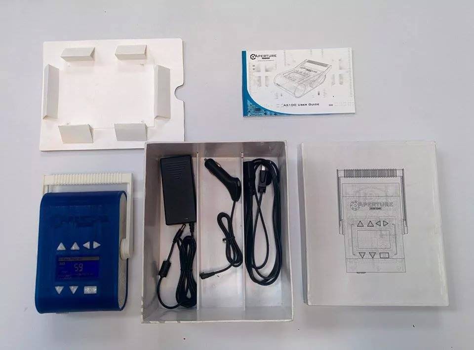
08/15/2015 at 19:04 • 0 commentsJanuary had rolled around, and it was time to wrap up my prototype. Literally :-)
I built a box from glossy paper prints, cut cardboard, and about a day's worth of frustration. I did my best to make it look as pretty as possible, and, as functional as you'd expect a box to be.
-
![]()
![]()
![]()
-
In retrospect, I'm not sure why I did design a box and user manual for this machine. I had gotten so caught-up in building things, that I failed to see any opportunity cost in building unnecessary stuff!
Now, at this point, I wasn't too sure of the quality of the x-ray beam I was producing. I didn't have any x-ray image sensors that could do a better job than my logitech webcam, but, it was plain to see that the beam was intense. But, was it coherent?
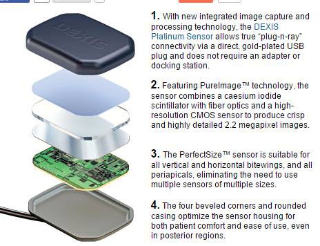
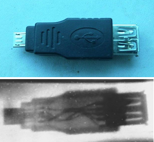
To answer that question, I bought a semi-working dental x-ray sensor. It consists of a CMOS photodiode array glued to a fiber optic plate, itself glued to a scintillation screen which converts x-ray photons into blue ones. Any image displayed on this screen will be coupled to the CMOS sensor array via the fiber optic plate (which increases resolution by making light rays parallel), for recording.![]()
Gotta love the marketing speak.
Unfortunately these sensors cost a great nickel and penny; far too much for me to afford. I ended up purchasing a broken one, with the hope that there might be something I can do to fix it.
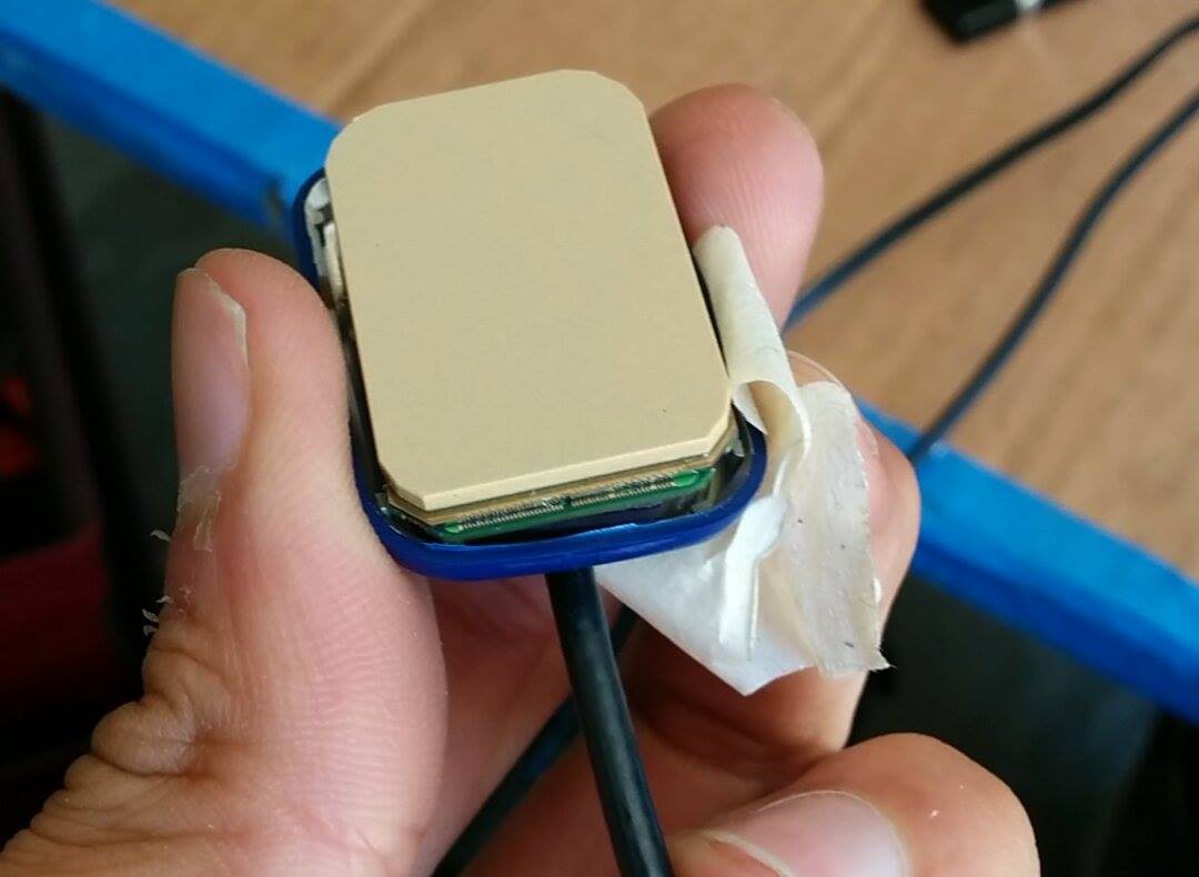
To my dismay, the problem turned out to be one of broken bond wires.
-
![]()
-
Fortunately though, under close inspection it appeared that only a few were actually broken; the rest were just bent at all odd angles.
So, how did I fix them?
-
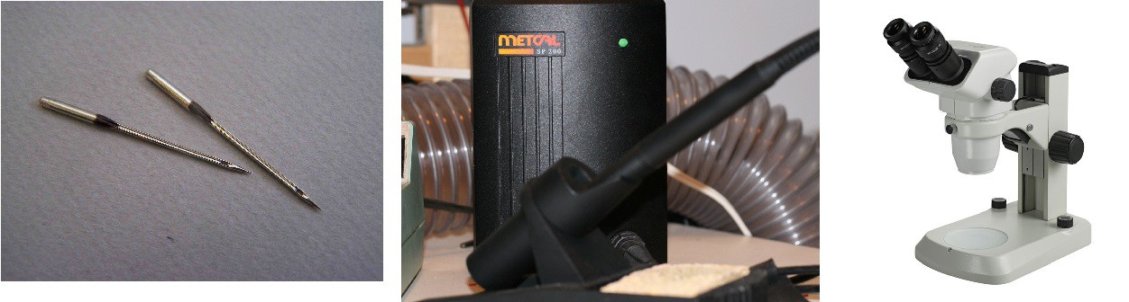
![]()
-
By wiring a sewing needle to a metcal iron, wetting it, and very carefully soldering the bond wires back in place after moving them to the correct position with another needle.
This might be news to many folks, but, a healthy human hand is capable of micrometer positioning! The only thing that limits your ability to move that precisely is your eyesight, however, a stereo microscope can readily solve that problem. I don't have any photos of the repair process, but, when all was said and done, it took about 5 careful hours to complete.
So, how were the results?
-
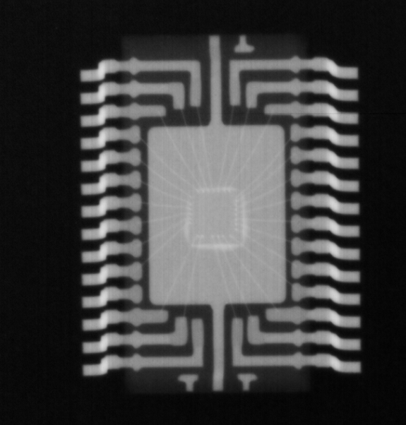
![]()
-
Amazing, to say the least. The above photo is one looking through a cheap calculator. Note, that the 35 micron-wide bond wires are visible inside the main IC! At this energy, (50keV), silicon, and the rubber buttons are wholly transparent.
-
The following picture is one of an SD card.
-
![]()
-
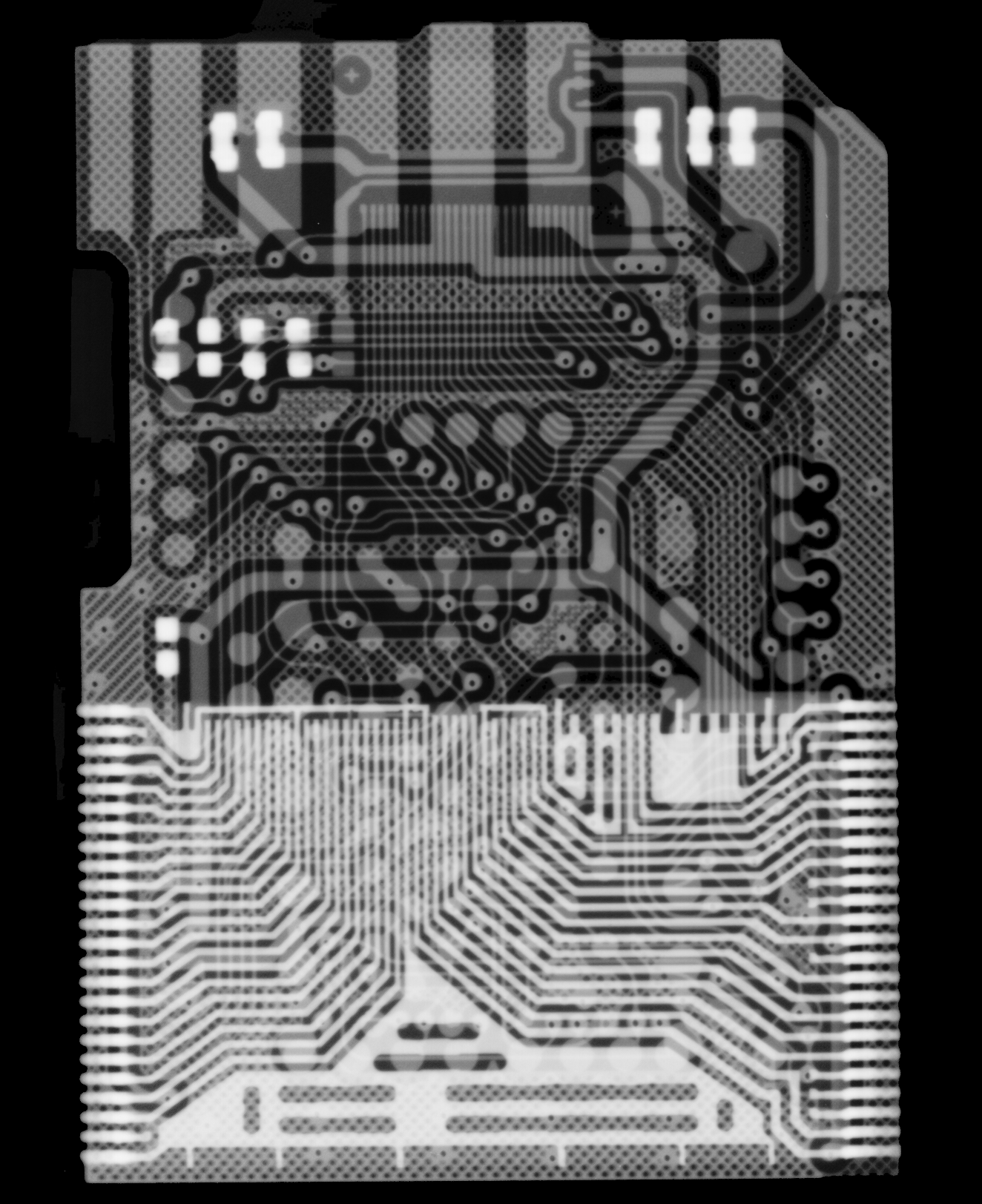
And this one, of a micro-SD card.
-
![]()
-
To say I was floored by how beautiful these radiographs were, would be an understatement.
-
December 2014 - Testing, verification, documentation
08/15/2015 at 18:00 • 0 commentsAt the end of November, I just about had all the electronics designed and working reliably. My code had been written, it seemed to work well, and overall things were looking bright. However, it was now time to assemble everything I neglected, including the high voltage oil tank.
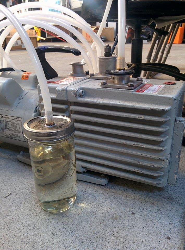
Why an oil tank?
To run an x-ray tube, you need a very substantial voltage: anywhere from 60 to 80 kiloVolts is not uncommon! At these voltages air is unfortunately a pretty poor insulator, and will break down readily to the detriment of your high voltage components. Oil on the other hand, tends to be a pretty good insulator.
At first, I tried taking baby oil from the local grocer, and pumping it down under vacuum to drive out all of the water.
-
![]()
-
For some time this proved to be sufficient, however, after a while I noticed some sparks in the (leaky) oil tank. Clearly, I needed real dielectric oil!
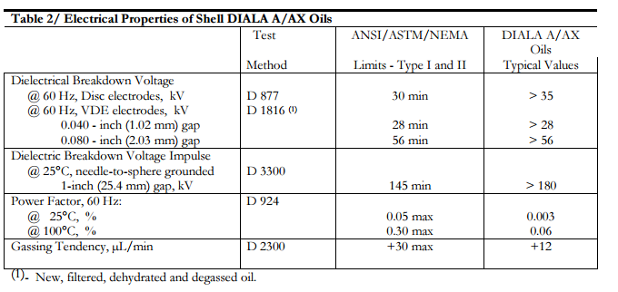
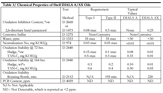
Unfortunately, just going out and buying dielectric oil isn't the easiest thing to do. It's sold only in 55 gallon drums, and, to buy any less of it means you're going to need a friend with such a drum. That was not something I had, but, after about 20 phone calls to companies around the bay area, I found a motor repair shop which was willing to let me fill up a jar of Shell Diala AX.
The specs of this oil are amazing!
![]()
![]()
It's not often you see "water" measured in units of PPM.
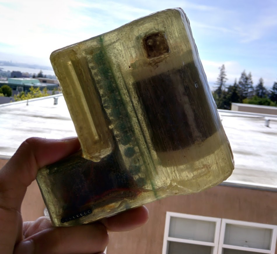
Using this oil solved the sparking issue, and covering the 3D printed oil tank in several layers of epoxy fixed the leaks.
![]()
-
In a way that's quite pretty, if a bit lumpy.
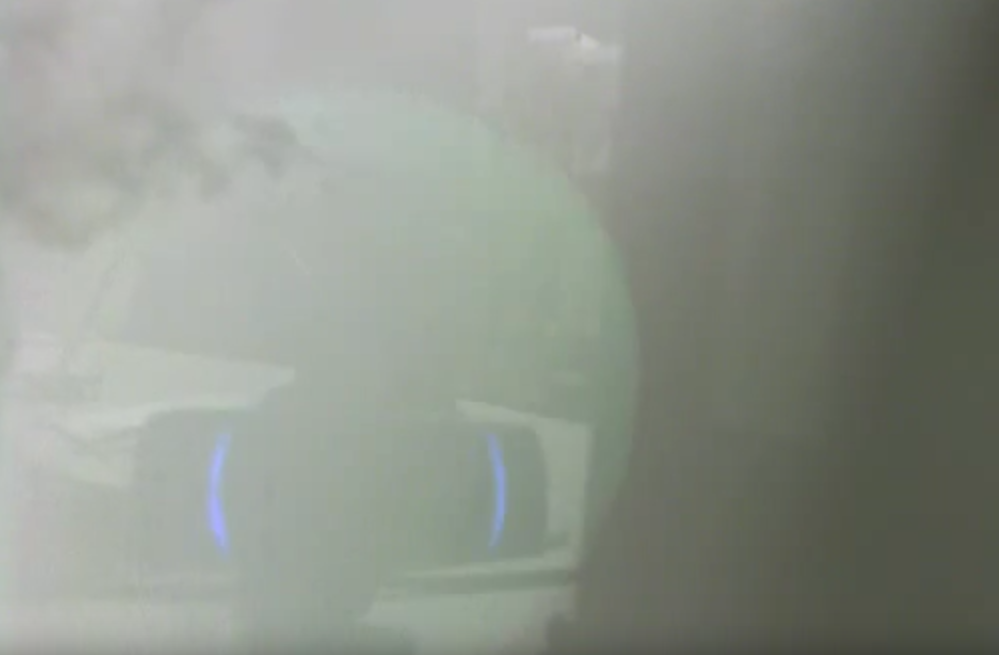
Following this, I had my first real x-ray beams. Interestingly enough, on a phosphor screen, they were bright enough to see in a semi-lit room with the unaided eye.
-
![]()
-
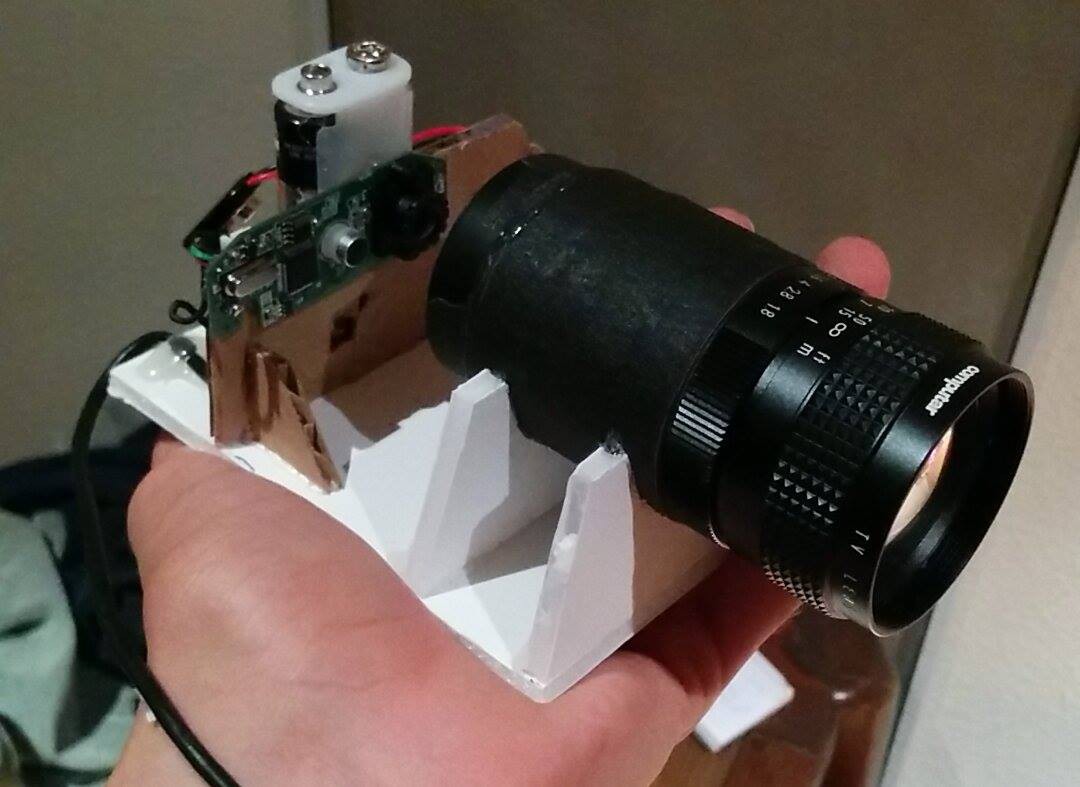
To capture x-ray images, I attached a lens to an image intensifying tube, and, placed that in front of a Logitech webcam. With a mirror, this assembly could view the image from a phosphor screen without picking up too much noise.
-
![]()
-
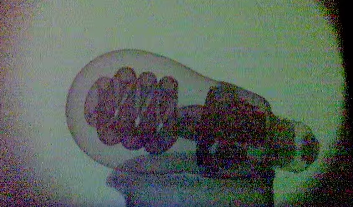
And, how did it turn out?
-
![]()
-
A little noisy, but clearly, working!
Somewhat.
Every so often, I encountered the strangest problem where the machine would simply turn off during an x-ray exposure. This sometimes was preceded by what I can best describe as "static shock sounds". Furthermore, when the x-ray machine's lid was off, it wouldn't have this issue. This puzzled me for a bit, as I had bypass capacitors everywhere, and my oscilloscope didn't suggest there was any noise in the circuit crazy enough to turn it off.
As one would have it, the problem turned out to be
Electro-static noise from the high voltage oil tank, coupling to the LCD panel.
Really. It was the E-Field.
-
![]()
-
Copper foil fixed it. Crazy, huh?
To teach people how to use the x-ray source, and to serve as a short "how to" on radiography, I made a handbook to go along with the machine (which is now lost, for reasons to be described later).
-
![]()
-
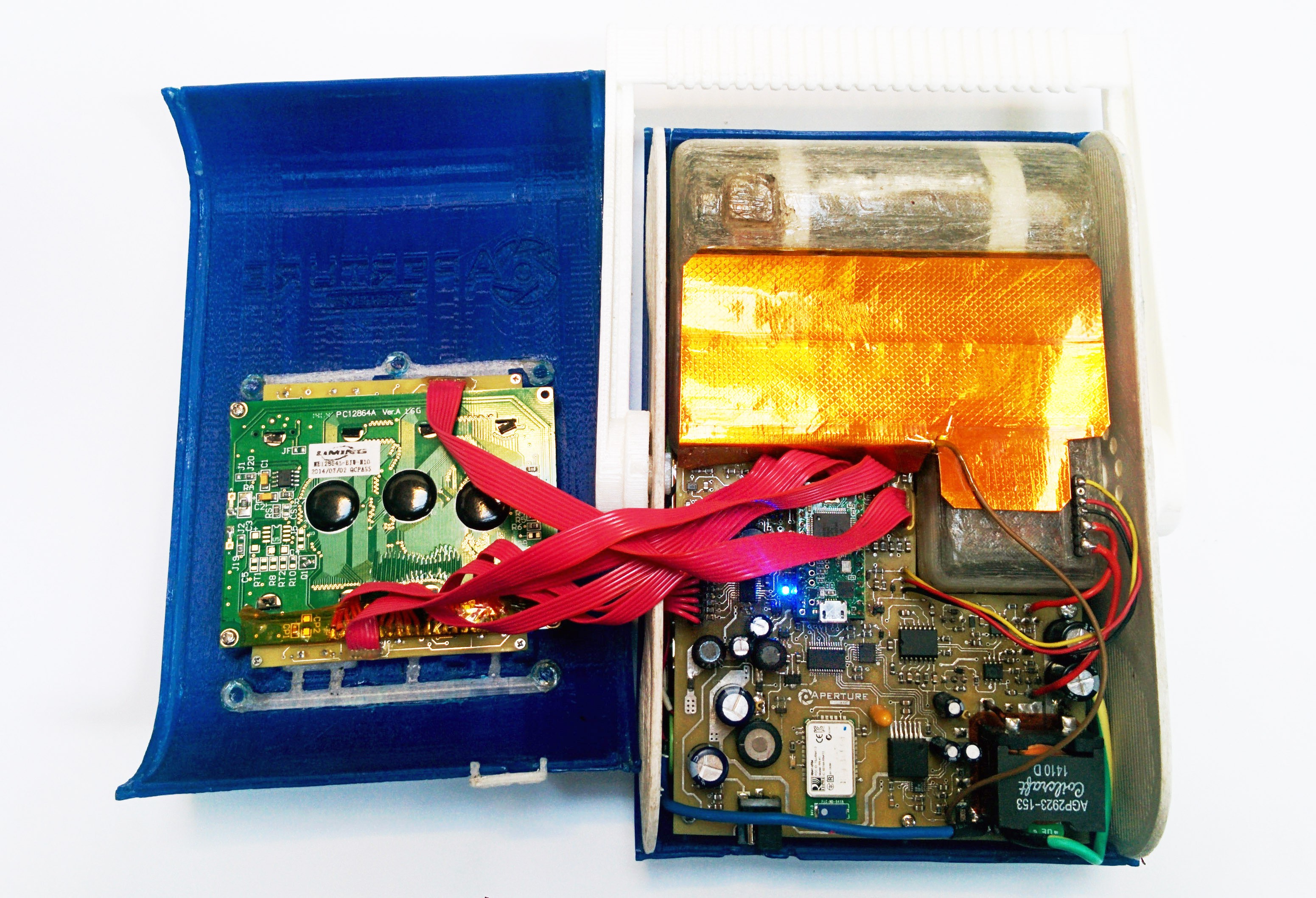
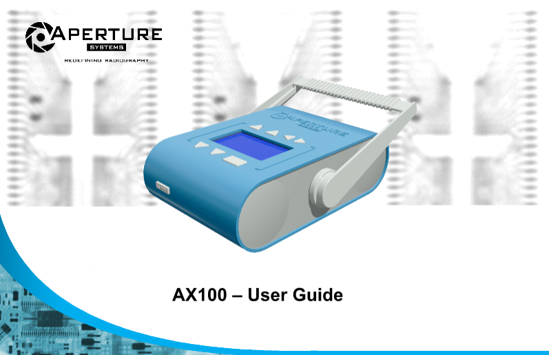
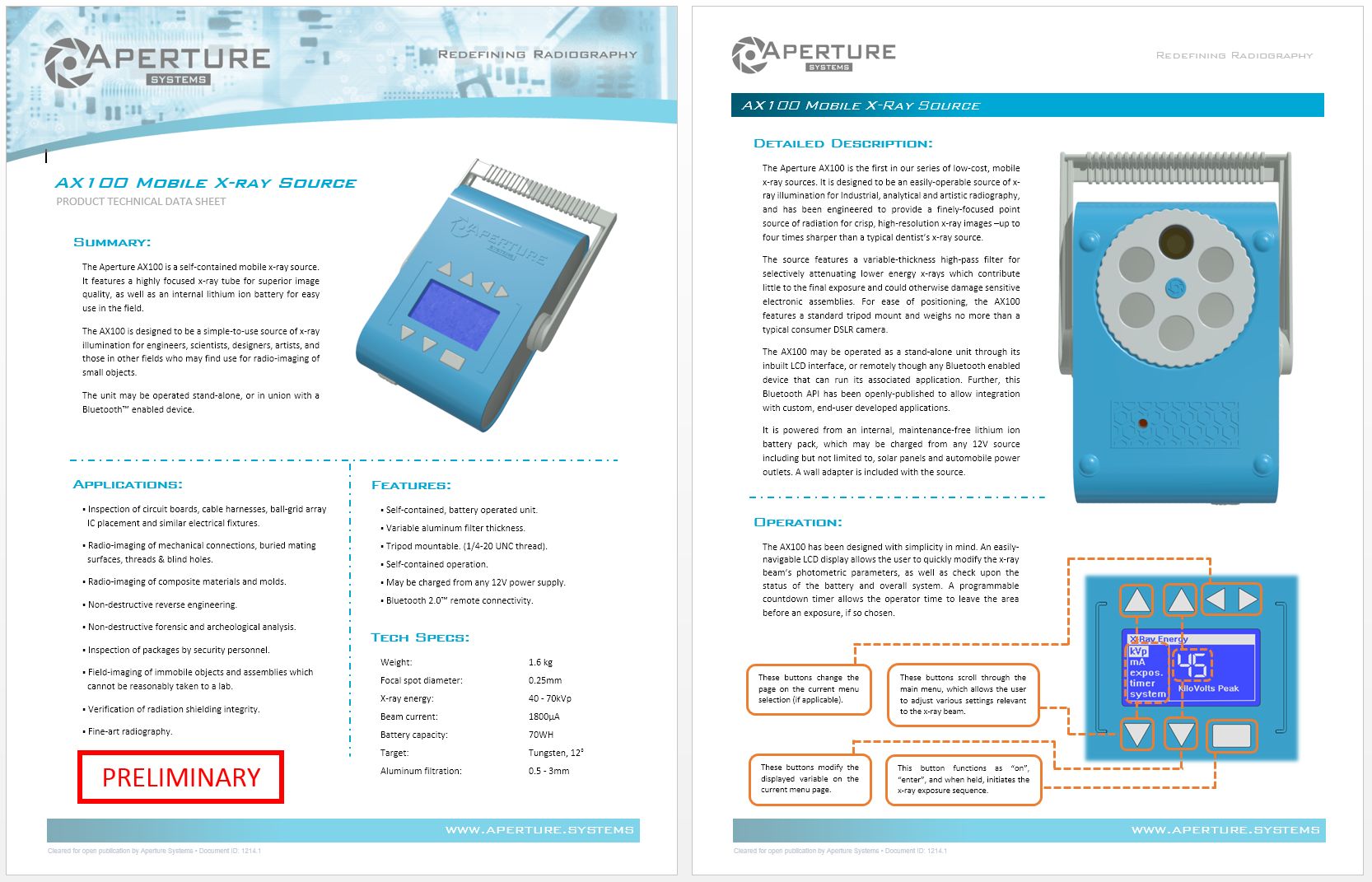
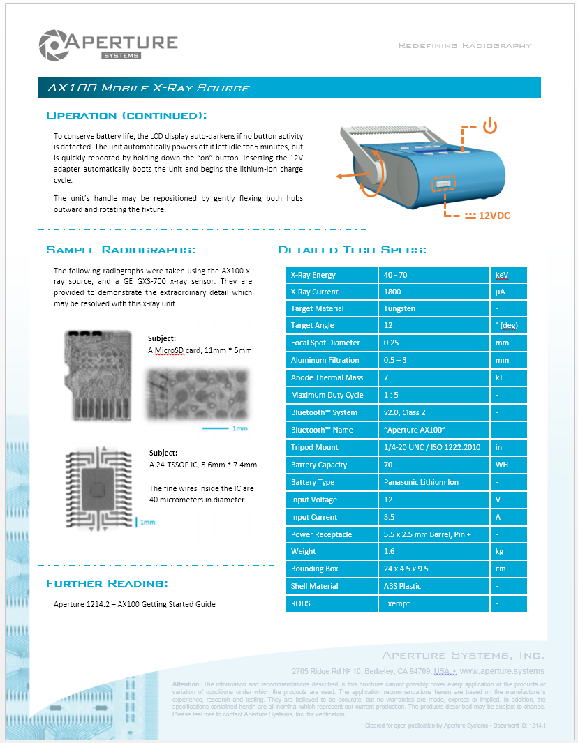
And, a datasheet that describes all of its functions!
-
![]()
![]()
-
At this point, what I had built was starting to look pretty dang cool!
Low Cost X-Ray Systems for Developing Nations
This is the result of 3,500 man-hours of labor and love, but we need your help to push it forward, HAD community


 -
- -
-