 Lex Kravitz
-
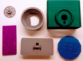
1Print out the six 3D parts
The print needs to be of decent quality. It is a mechanical pellet dispenser, so if your print is poor it may jam or not work correctly. I printed these in PLA on a Sindoh 3DWox printer. STL files located in the files area.
-
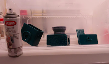
2(optional) Spray the 3D parts with clear acrylic
This is to protect them from mouse gross-ness. Don't spray the pellet disk. Also no need to coat the insides of the parts. Let them dry for a couple days before putting them with mice.
-
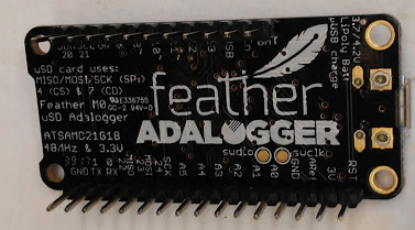
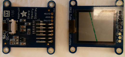
3Add headers to the Adalogger M0 board and the Memory Display
Solder straight male headers to the Adalogger board, instructions here: https://learn.adafruit.com/adafruit-feather-m0-adalogger/assembly
Solder six 90 degree headers from Vin to CS pins on the Memory Display. You can plug the 6-wire harness in while soldering to keep the spacing correct.
-
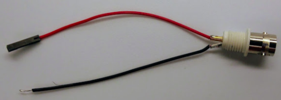
4Prepare the BNC connector
Put a bare wire on the ground pin, and a 0.1" female header on the signal pin. Tin the end of the wire.
Screw the BNC connector into the FED base. (this step seems a bit out of place here but this connector needs to be mounted in the base before the ends are soldered).
-
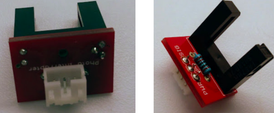
5Prepare photo-interrupter board (PI)
Solder the PI into the Sparkfun breakout board, solder on a 1K resistor (the board says to use a 220Ohm resistor but we found 1K doesn't impair the function of the PI and consumes less power), and solder on the 3 pin JST connector. Be careful with the orientation of the connector, it's important! Plug the wire into this 3 pin jack.
-
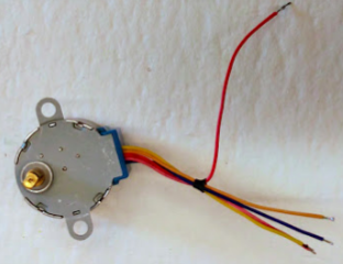
6Prepare the stepper motor
NOTE: The stepper we chose was purchased from Adafruit and has 1/16 gearing. This is critical! You can find cheaper ones on Amazon that do not have this gearing but they will not work in this design without modification. See log entry about our experience with different steppers and servos.
Cut the connector off, leaving about 20cm on the red wire, and 15cm on the others. Strip about 1cm from each and tin the ends.
-
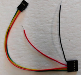
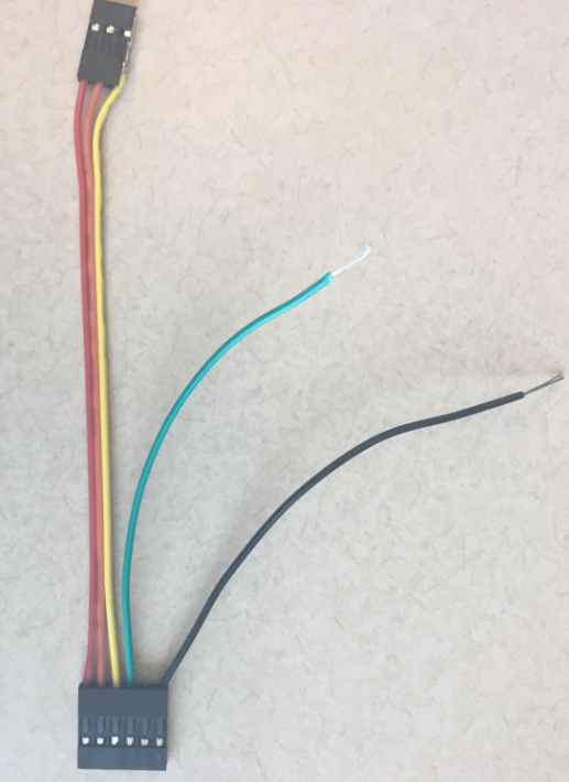
7Prepare the 6-pin wiring harness
Cut one 6-pin connector on the 6-pin jumper in half with snips, leaving the green-yellow-orange connections intact. Cut the other 3 wires to about 10cm long and strip 1cm from the red and black wires. Remove the brown wire completely.
Note: It looks like Sparkfun changed the wiring colors since we bought these the first time! They may look like this - colors obviously don't matter, the order does:
-
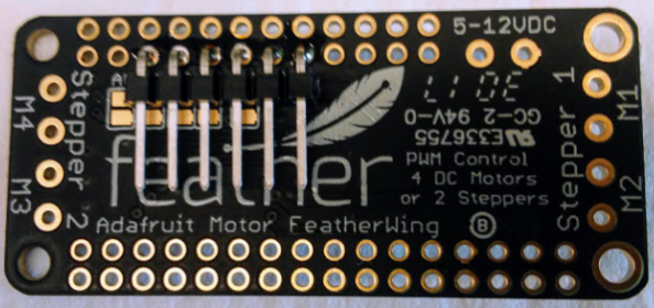
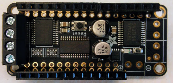
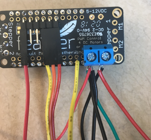
8Prepare the motor shield
There are 5 things that need to be soldered onto the motor shield. I've found this order of soldering to be easiest:
- Start by soldering a 6 pin 90 degree header on the back as shown in photos. They are unlabeled but it’s the 3rd to 8th pins from the left if the board is oriented with “feather” upright. You can plug the 6-wire harness in to these pins while soldering to keep the spacing correct.
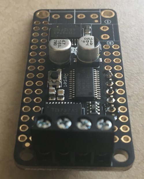
- Solder the screw terminals on M3 and M4 (you can also put screw terminals on M1 and M2 if you’d like, but this is not necessary).
- Solder low profile headers onto the front to interface with the Adalogger. Note: If you use the Adalogger to align these headers make sure you don't push the male Adalogger pins all the way through and solder the boards together, it's possible to do so.
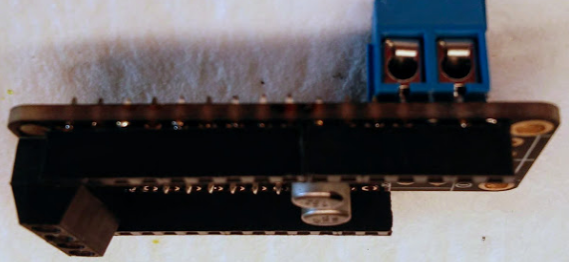
- Solder the 2-pin screw terminals into the 2nd and 4th from the right pins on the back. These will be PWR and GND if you line up the Adalogger board.
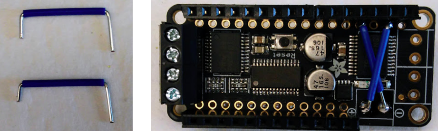
- Finally, cut short jumpers, and jumper the screw terminals to the (+) and (-). You’ll want a very fine soldering tip for this one.
- I know..... someday we'll do a custom PCB to simplify all this! Update: see our design with custom PCB here!
- Start by soldering a 6 pin 90 degree header on the back as shown in photos. They are unlabeled but it’s the 3rd to 8th pins from the left if the board is oriented with “feather” upright. You can plug the 6-wire harness in to these pins while soldering to keep the spacing correct.
-
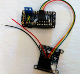
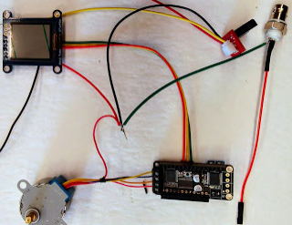
9Assemble the electronics!
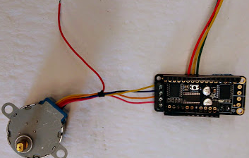
- Plug the 6 pin cable into the header on the screen, and the 3 pin connection to the motor shield
- Screw the motor wires into the motor terminals: from top: yellow blue orange pink (leave red out for now)
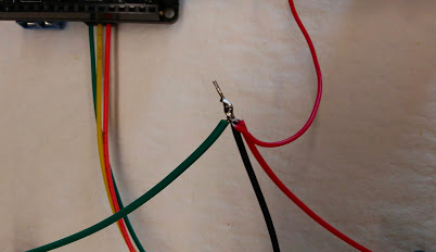
- Strip the ground wires from 4 components (BNC, PI, Screen, and motor) to ~1cm if they aren't already, and twist together and put a drop of solder to keep them together. Be careful of colors: the ground from the screen and motor are red, the ground from the PI is black, and the ground from the BNC is whatever color wire was used there.
- Strip the power wires from the remaining 2 components (these are a black wire from the screen and the red wire from the PI) and twist together and attach with a drop of solder.
- Screw the power and ground connections into the terminal blocks
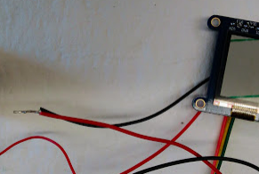
- solder the PI signal wire into pin A1 (2 pins to the left of the terminal blocks).
- Push the BNC signal wire onto pin 5 on the back of the board.
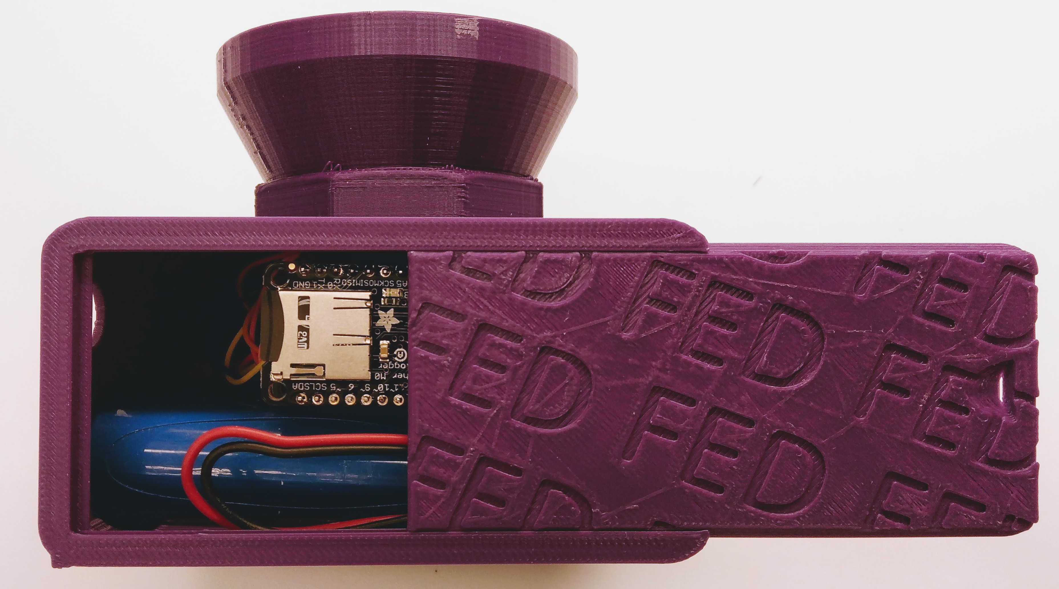
- Insert a microSD card into the slot (this is needed to boot up FED).
- That's it!
- Plug the 6 pin cable into the header on the screen, and the 3 pin connection to the motor shield
-
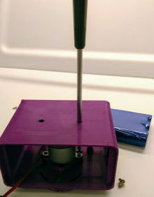
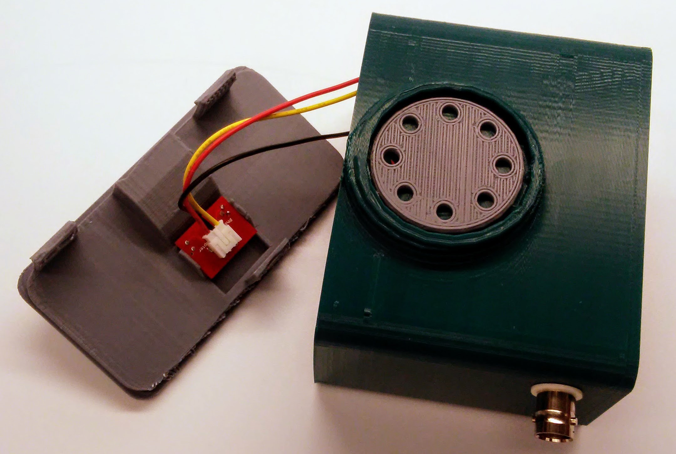
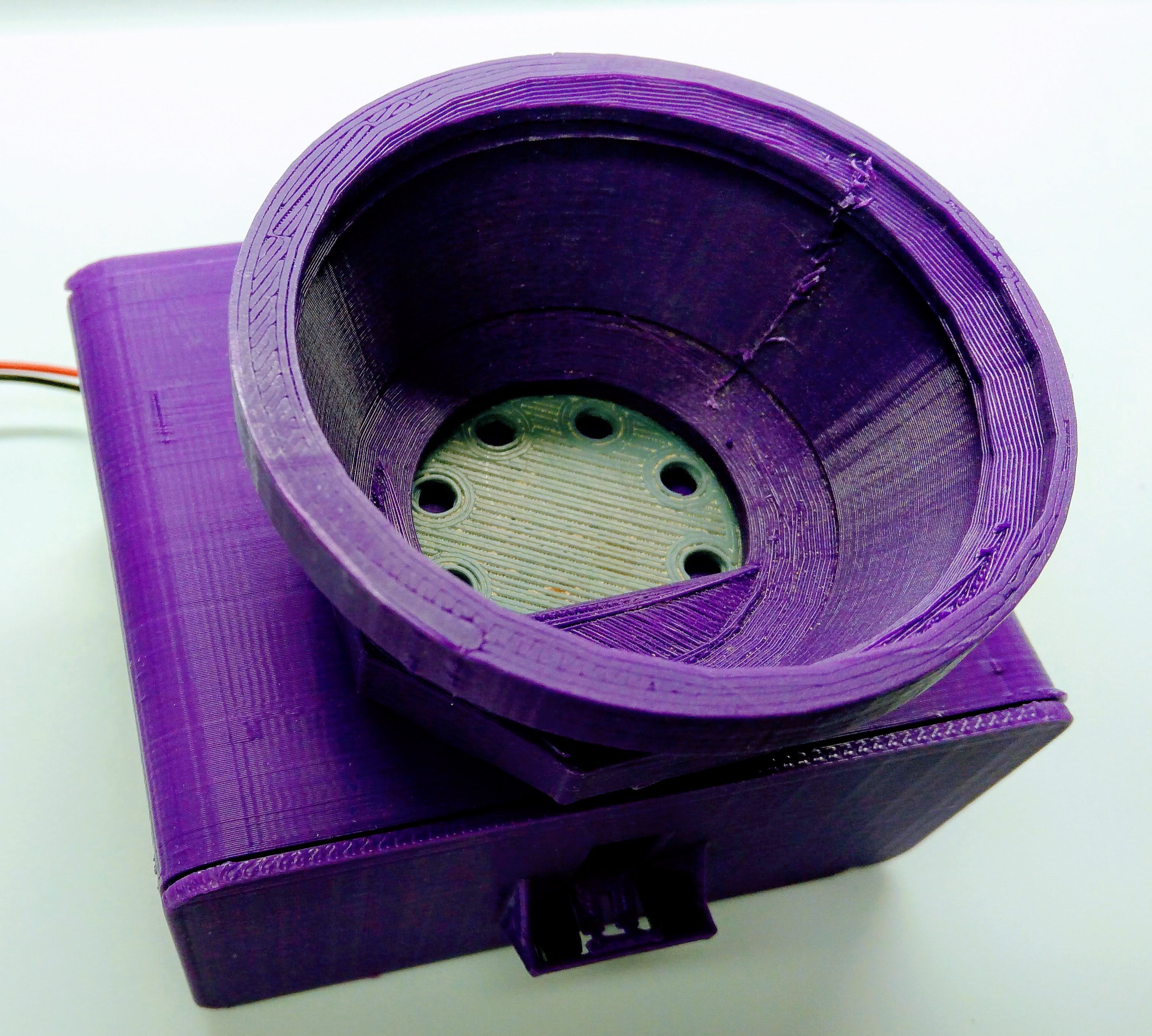
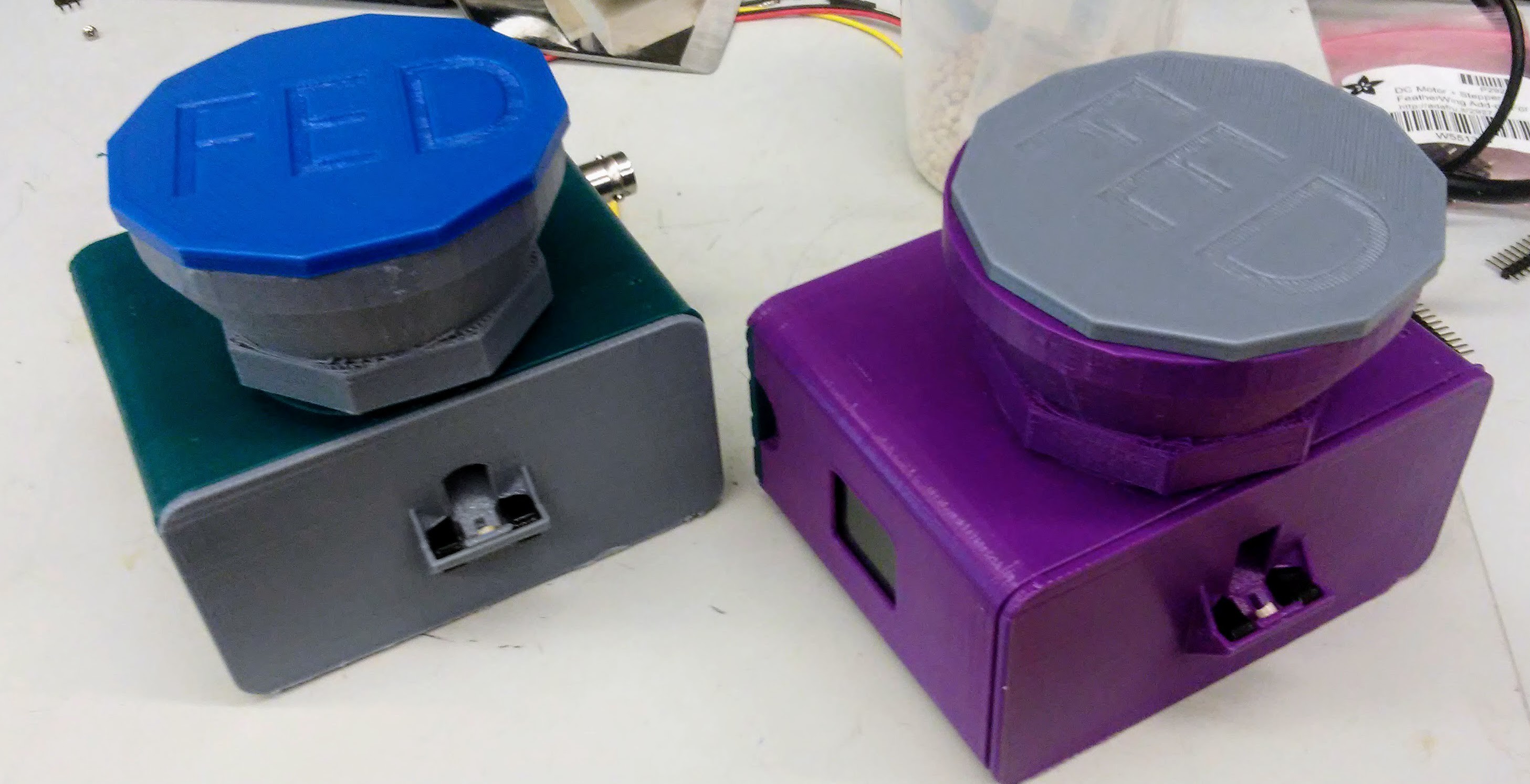
10Put FED together!
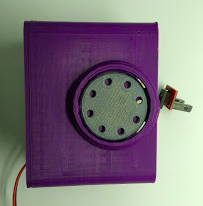
- Screw the stepper into the base with 4 x 1/4" screws. Use holes in base to access with a screwdriver
- Push the pellet disk onto the stepper
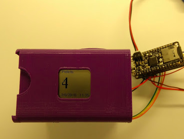
- Position the screen and snap it into place
- Separate the Adalogger and motor boards and screw the motor board into the base with 2 x 1/4" screws.
- Snap the PI into the front plate, and snap front plate into place
- Put the Adalogger back on the motor board
- Screw the silo and lid on top
- Push the battery into place and plug it into FED.
- Slide on the back cover.
- Fill with pellets and flash code (next step) to confirm that it dispenses!
![]()
![]()
![]()
![]()
![]()
- Screw the stepper into the base with 4 x 1/4" screws. Use holes in base to access with a screwdriver
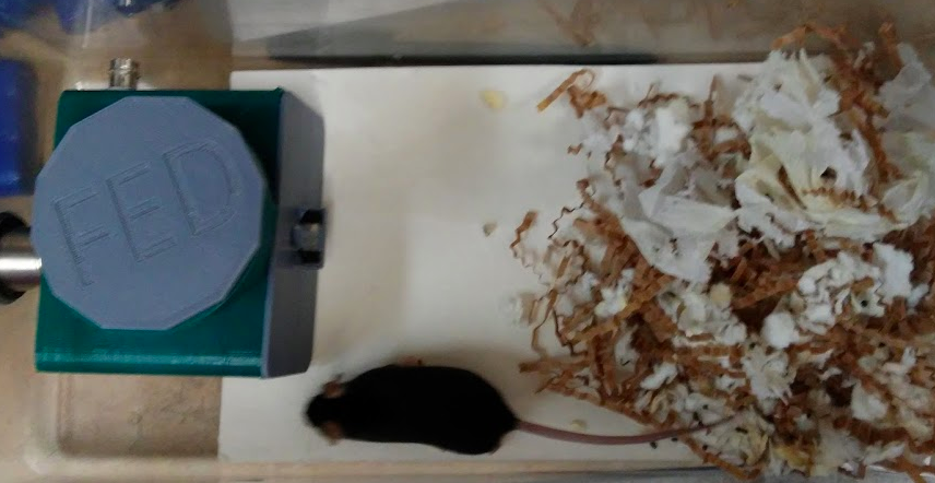
Feeding Experimentation Device (FED) 2.0
FED measures food intake in mice. It is battery powered and designed to be used in rodent colony caging.

Discussions
Become a Hackaday.io Member
Create an account to leave a comment. Already have an account? Log In.