Close
0%
0%

LiFePO4wered/USB

LiFePO4 battery technology, made easy for makers

Similar projects worth following
Starting from
$13.95
xorbit has 1742 orders / 67reviews
Ships from United States of America
Voltage regulation wastes power. If you use an LDO, you waste power when you draw current. If you use a switching power supply, you waste power when your device is sleeping. Low power electronics tend to operate under both conditions: they sleep most of the time, then briefly wake up and do something that consumes power.

Some systems can get away with using a lithium coin cell. The voltage range of such a cell allows it to power 3V systems without regulator. The downside is that they have high internal resistance and are often incapable of providing the current necessary to power transmitters or actuators. Wouldn't it be great if there was a battery technology that had a 2-3.6V voltage range, low self-discharge, low internal resistance so it could deliver high current, was rechargeable and had a large number of recharge cycles?

There is! It's called LiFePO4 (lithium iron phosphate). Now you can easily use it in your projects with LiFePO4wered/USB!

LiFePO4 is a battery technology that finds wide application in power tools and electric vehicles. It is an inherently stable chemistry (which makes it safe), is environmentally friendly (no heavy metals), has very high power density and many more recharge cycles than other Lithiums.

It also has a perfect voltage range for use with electronics: 2 - 3.6V. This means most modern chips can be powered without the use of a voltage regulator, which tends to be a big power waster in low power systems.

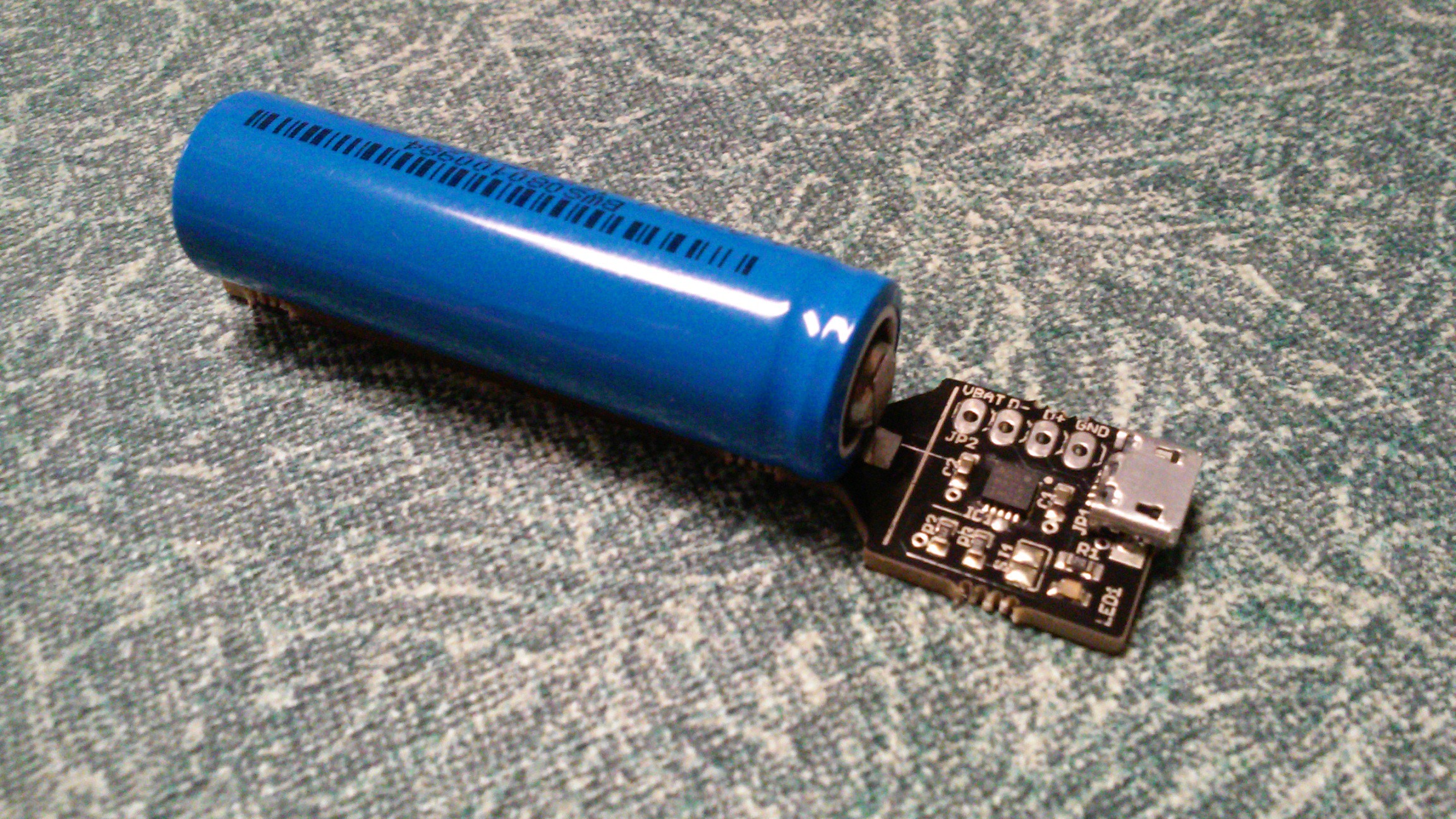
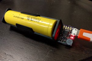
So here is an easy to use module to get started with LiFePO4 in your own designs. It's basically a battery with an integrated USB charger. All connections are on a 0.1" grid for easy integration. Take power straight off the battery holder terminals, or if that doesn't fit in your design, cut off the battery terminals and connect to the 0.1" header footprint.

So stop using old lithium cells that require a voltage regulator and last only a couple hundred cycles, and upgrade to the next level with LiFePO4!

LiFePO4wered-USB-Product-Brief.pdf

force-download - 384.72 kB - 02/02/2016 at 18:13

Preview

IFR14500EC-0.5Ah.pdf

force-download - 197.72 kB - 02/02/2016 at 18:13

Preview

LiFePO4wered-USB-mechanical.eps

x-eps - 58.85 kB - 02/02/2016 at 18:12

Download

LiFePO4wered-USB.pdf

force-download - 11.76 kB - 02/02/2016 at 18:12

Preview

  • 1 × MCP73123 Power Management ICs / Power Supply Support
  • 1 × LiFePO4 3.2V 550mAh 14500 cell

  • New battery holders and cells!

    Patrick Van Oosterwijck11/02/2016 at 19:23 0 comments

    A complaint I sometimes heard about the LiFePO4wered/USB (the only complaint really) was that the battery didn't fit well in the battery holder. This was definitely justified: being a perfectionist myself, it was something that bothered me as well.

    There's a solution now: all new units will be shipped with a new battery holder and cell that provide a much better fit:

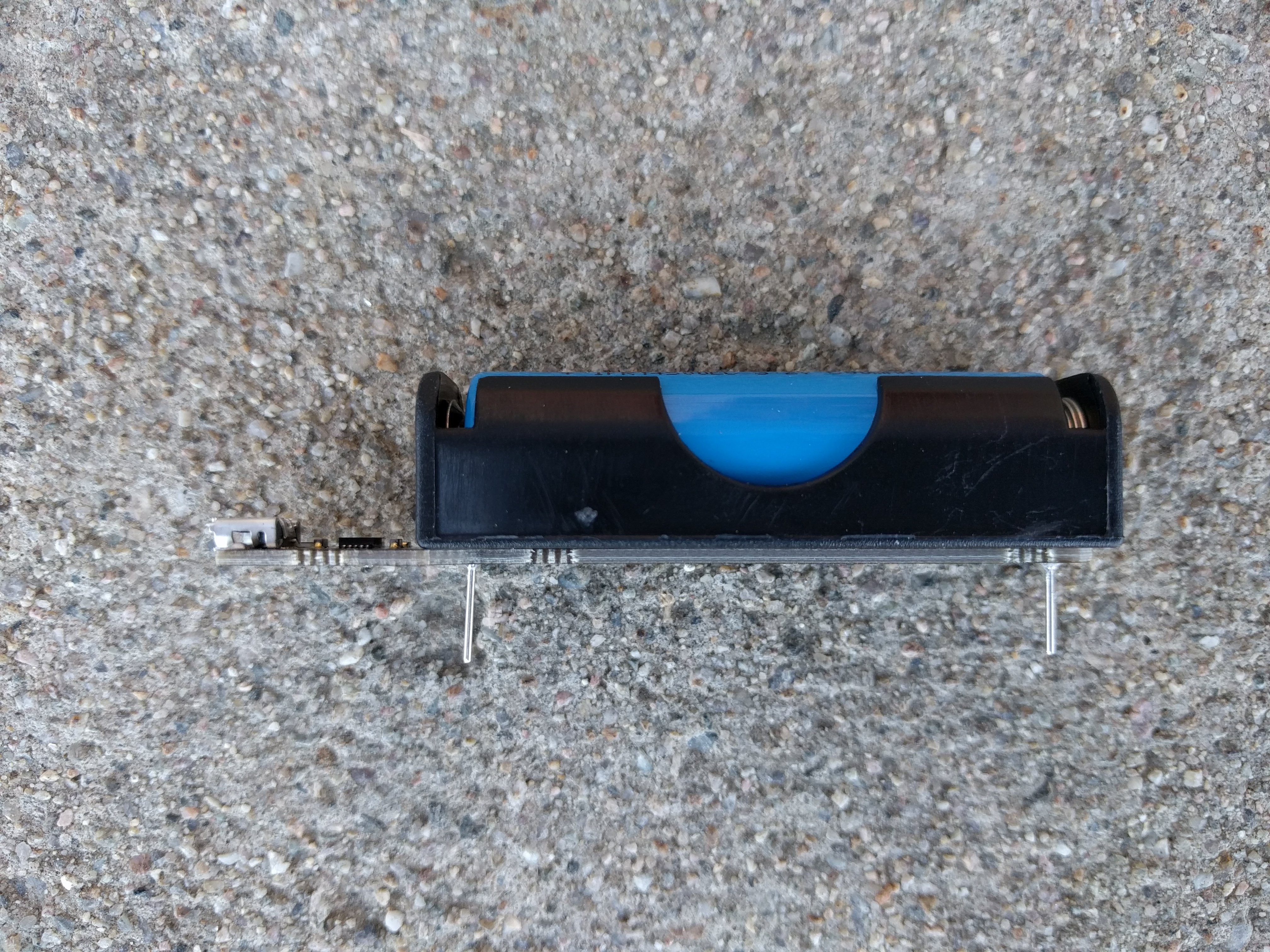
    The new cell is smaller (shorter) because it has a flat top instead of a button top. The old battery holder had a reverse polarity protection feature in the plastic, and although the new cells seem to work in it, the feature is really designed for a button top cell. So I decided it was safer to switch to the new battery holder I've been using for the #LiFePO4wered/Pi and also use it for the LiFePO4wered/USB now.

    The only relevant difference (aside of a much better looking unit :)) is that the battery holder pins are shorter than they used to be. I already altered the product brief to allow for the variation in physical dimensions a while back.

  • Video footage of new build!

    Patrick Van Oosterwijck08/04/2016 at 00:47 0 comments

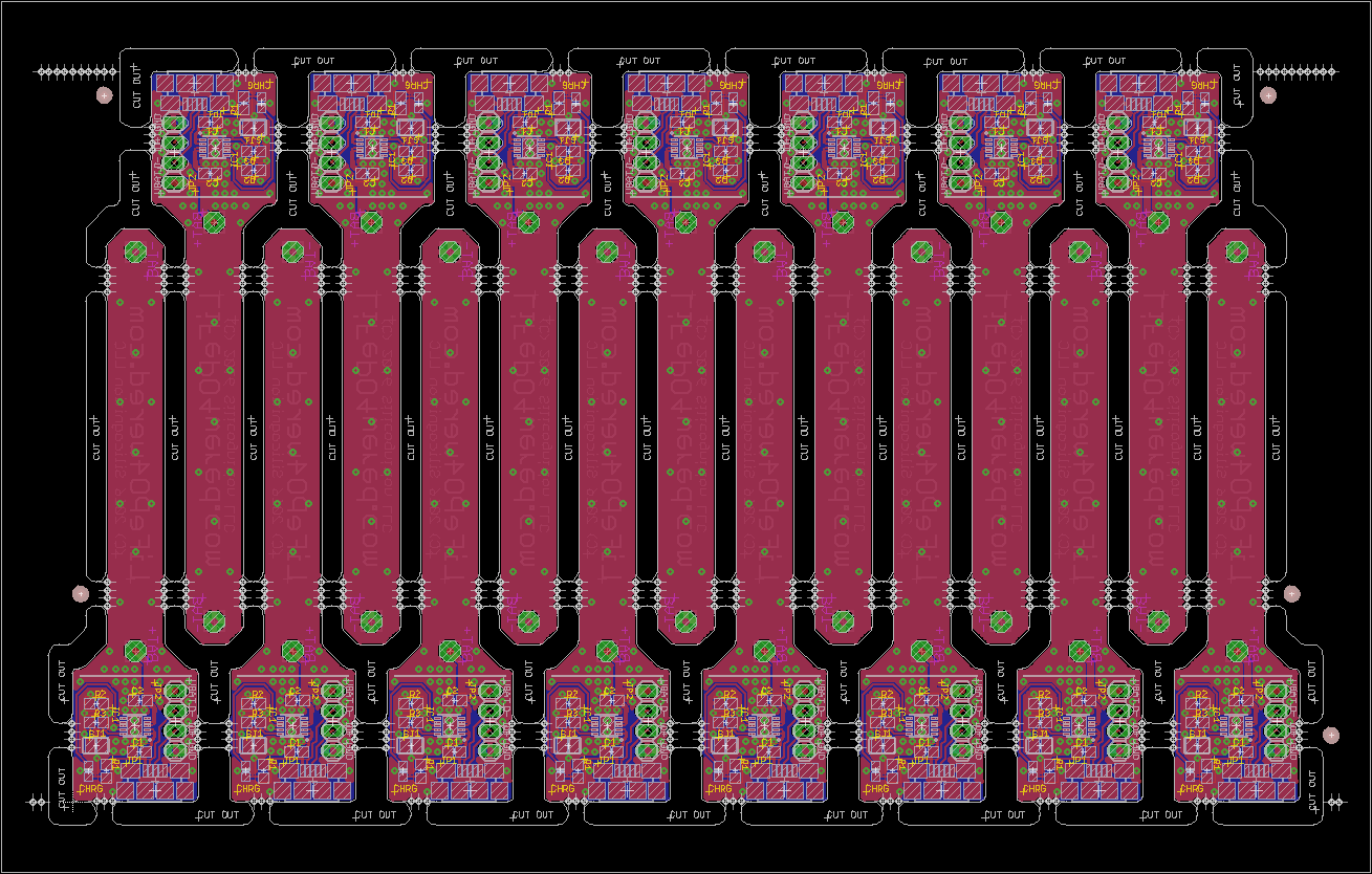
    Since I am using a contract manufacturer that's right here in town (Colorado Tech Shop), I asked them if I could come over to observe when my panels were assembled, and they graciously permitted me to do so. Below is a video compilation showing some of the assembly process:

    Thanks for sharing some of your experience with me Luis! :)

    I now have 300 LiFePO4wered/USB boards with the thermally improved layout that is needed to build the #LiFePO4wered/Pi. They are also available for your own projects on Tindie!

  • Thermally improved panels!

    Patrick Van Oosterwijck06/24/2016 at 17:49 0 comments

    Because of my continuing development of the #LiFePO4wered/Pi, I have ordered new LiFePO4wered/USB panels with the new thermally improved layout. Read the details here!

  • Thermally improved layout

    Patrick Van Oosterwijck06/16/2016 at 16:00 0 comments

    Since not everyone is following both this and my #LiFePO4wered/Pi project, I'll add a log here to link to a cool new development for the LiFePO4wered/USB. To deal with heat dissipation issues limiting the charge current for the #LiFePO4wered/Pi, I made a thermally improved layout of the LiFePO4wered/USB board.

    Check out the thermal images in this project log!

  • Investigating solar

    Patrick Van Oosterwijck05/13/2016 at 18:30 0 comments

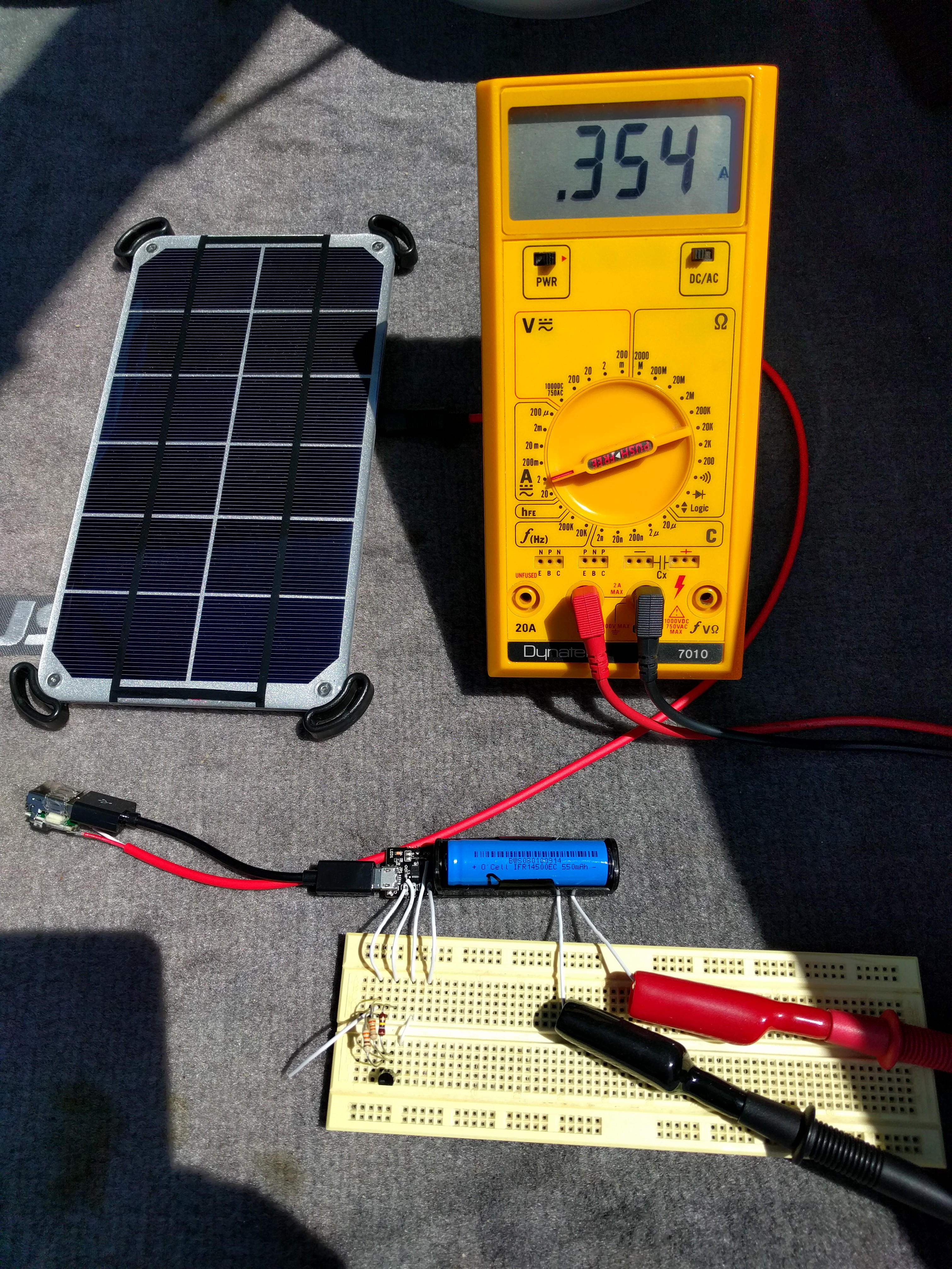
    Jeff Crystal from Voltaic Systems was nice enough to send me a 3.5W and 6W solar panel to experiment with. Since these are bare panels, I was pretty sure that connecting them directly to the LiFePO4wered/USB charger was not going to work well. For one thing, the unloaded output voltage of the panels is 7V, and the MCP73123 enters overvoltage protection at 6.5V. So once charged, and not loading the panel, you could end up in a situation where the battery wouldn't be charged again because the panel's voltage was too high. It would be flaky at the least. So I decided to add a buck regulator to keep the voltage at 5V and below.

    It still didn't work well. The system would end up in a hiccup mode. The charging chip would decide the voltage was high enough, turn on the charging current, which would make the voltage sag, and the chip would stop charging. Over and over.

    The problem is that the LiFePO4wered/USB uses a fixed charging current, set with a resistor. So I decided to add a little transistor current source circuit connected to the PROG pin of the charging chip to see if I could make the charge current dependent on the input voltage, so the charger wouldn't instantly dunk the panel voltage when starting to charge. It seems to work great!

    I will need to do some more testing with this, but it could make it possible to add a solar option to the LiFePO4wered/USB in the future.

  • Cyber Monday!

    Patrick Van Oosterwijck11/30/2015 at 17:14 0 comments

    LiFePO4wered/USB is in the newsletter!

    Only today, it's $2 off with code C73700C.

  • LiFePO4wered/USB with tabbed cell now live on Tindie!

    Patrick Van Oosterwijck09/14/2015 at 19:36 0 comments

    For anyone who is interested in buying the version with soldered tabbed LiFePO4 cell, it is now live on Tindie! :)

    LiFePO4wered/USB with tabbed LiFePO4 cell

  • Spot welded battery!

    Patrick Van Oosterwijck09/03/2015 at 22:44 0 comments

    I got a battery spot welder, so now I can weld on my own tabs for a version without the battery holder! Lighter, more compact (reduced height), better looking. Coming soon to Tindie. :-)

  • Eagle files on Github!

    Patrick Van Oosterwijck08/17/2015 at 21:50 0 comments

    LiFePO4wered/USB is now open source hardware! The Eagle design files were uploaded to Github, and I just added a link to the project. Enjoy, and don't forget to support my development by buying some on Tindie! :-)

View all 9 project logs

Enjoy this project?

Share

Discussions

Le Roux Bodenstein wrote 06/30/2019 at 12:53 point

Something I don't quite understand from either this project or the MCP73123 datasheet: It says the maximum regulated output voltage is 3.618V. It also mentions 0.5% tolerance. So that means a maximum of 3.7989V. If you have the load (ie. your project) connected while charging which I'm assuming most would want to do, that means that whatever 3.3V part you're powering will see that voltage, right? And every 3.3V part's datasheet I've seen says absolute maximum 3.6V.

How do you deal with this or is this just not a problem?

  Are you sure? yes | no

Patrick Van Oosterwijck wrote 07/01/2019 at 20:32 point

It looks like there's a problem with your math, you seem to have calculated 5% tolerance instead of 0.5%. :)  A tolerance of 0.5% gives 3.63 V worst case, which isn't an issue.

  Are you sure? yes | no

Le Roux Bodenstein wrote 07/01/2019 at 20:35 point

Oops. That's good to hear. I'm happy to be wrong on this one ;)

  Are you sure? yes | no

W5FCX wrote 02/18/2018 at 22:03 point

Thanks for sharing Patrick.  Great design.  Loved watching the production line video!

  Are you sure? yes | no

John (EBo) David wrote 03/22/2016 at 09:26 point

Does this model also allow for power loss sense to facilitate shutdown?

  Are you sure? yes | no

Patrick Van Oosterwijck wrote 03/22/2016 at 14:54 point

No, this is just the charger baseboard.  Basically a battery holder with USB charge circuitry.  Any undervoltage protection would need to be implemented in the customer circuitry, like I did with the #LiFePO4wered/Pi.

  Are you sure? yes | no

Thomas wrote 03/02/2017 at 07:27 point

Hello Patrick,
good work - thanks. Do you have a link to a circuit diagram for a suitable undervoltage protection?

  Are you sure? yes | no

Patrick Van Oosterwijck wrote 07/28/2018 at 04:59 point

Hello Thomas,

Take a look at the schematic for my #LiFePO4wered/Solar1 project, it has a low voltage cutoff circuit based on the NCP302HSN30.

  Are you sure? yes | no

W5FCX wrote 02/18/2018 at 22:01 point

The MCP73123 has built-in undervoltage protection from what the datasheet shows.

  Are you sure? yes | no

Nick Farrow wrote 03/18/2016 at 05:26 point

Great project. Let see if it comes on before my pi3 LOL

  Are you sure? yes | no

Mike Szczys wrote 09/15/2015 at 17:10 point

In case anyone is wondering, this is using the MCP73123 on the board. It would be great if you'd post an image of the schematic to save everyone from downloading the eagle files to browse.

Really cool build!

  Are you sure? yes | no

Patrick Van Oosterwijck wrote 09/16/2015 at 15:15 point

You're right, not all people have Eagle.  I added a PDF of the schematic to the Github repo and an image to the gallery!

  Are you sure? yes | no

Xark wrote 09/07/2015 at 19:18 point

I just wanted to mention that I got a few of these from Tindie and I think they work great.  I used one in a "Bike Safety Blinker" project (ATTiny45 + WS8211 LEDs https://imgur.com/a/S0ugQ) where AA battery form-factor and long-lasting rechargeable power were desirable.  I would recommend them for other 3.3v projects.

  Are you sure? yes | no

Patrick Van Oosterwijck wrote 09/07/2015 at 19:24 point

Awesome! Great project, thanks so much for sharing. :-)

  Are you sure? yes | no

Paul Scott wrote 08/21/2015 at 06:46 point

Just hooked one of these up to an ESP8266 circuit and it works brilliantly! Getting a steady 3.3V from it. Battery life seems good too!

  Are you sure? yes | no

Patrick Van Oosterwijck wrote 08/21/2015 at 16:24 point

Thank you very much for reporting this Paul!  Nothing better than reports from users in the field to build credibility! :-)

  Are you sure? yes | no

mr.jb wrote 08/18/2015 at 20:24 point

A 15-20W version that can handle a Vin =8-9v would be nice.... aimed at portable solar panels and maybe even TEG.

I also  think you should consider a version without USB and battery case. Just the charger circuit... 

  Are you sure? yes | no

Patrick Van Oosterwijck wrote 08/18/2015 at 22:02 point
Thanks for the comment and skull mr.jb.swe!

Those would be some great variants you suggest. This is the first simple incarnation and I'm definitely planning some variants, to establish a "LiFePO4wered" brand of LiFePO4 based modules.  I agree a solar (wide input voltage) version would be awesome.  As is the case with other lithiums, low temperature charging is a problem.  So I'm planning to have a solar charging version that takes care of that for outdoor/solar use as well.

  Are you sure? yes | no

mr.jb wrote 08/19/2015 at 05:04 point

My favorite batteries are LiFePO4  8-10 Ah prismatic and Nanophosphate  ANR26650M1-B cylindrical 2A ( 7000 cycles at 1C !? )

Soon graphene  will be available like Zap &Go, taking that in consideration the absolute best would be the possibility to adjust battery float voltage.

And it is worth to note the difference between solar panels, teg and dynamo when it comes to mppt. 

http://www.eetimes.com/document.asp?doc_id=1279330

I think should should aim for durable device for portable power ( camping ) and your toughest clients could be people in the third world  (they need light and charge phones )

My current approach is a simple stupid solution with buck converter.....( but I think it can be tweaked in to a poor mans mppt charger )

  Are you sure? yes | no

Similar Projects

Does this project spark your interest?

Become a member to follow this project and never miss any updates