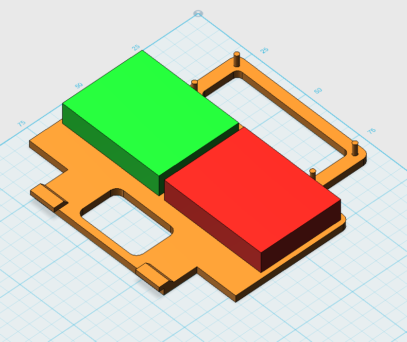
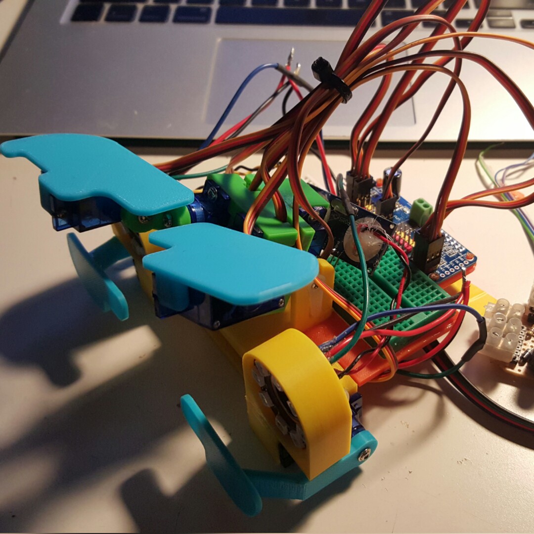
I'm still trying to get the wire mess controlled, to have an easy point to come back on a later point in time. On the backside there will be a PCA9685 16-CHannel 12-Bit PWM Driver board used for the servos and getting along with the ws2812b LEDs. I've heard about timer issues and just wanted to be safe. The red and green boxes are tiny breadboards for arduinos and servos.
I'll update this as soon as the print is done.


 davedarko
Discussions
Become a Hackaday.io Member
Create an account to leave a comment. Already have an account? Log In.
I'm not a great fan of the breadboards -- somehow the wires never stay where they were supposed to. Instead I tend to use breakouts with male pins, and stripboards (also with male pins). It seems to me that they give much better connections with female-female dupont cables.
Are you sure? yes | no
it's just for testing at first and holding the modules in place somewhere. I'll might just solder onto the arduino or make some pinheader plugs later.
Are you sure? yes | no