3D printable logic that works with water at low pressure
To make the experience fit your profile, pick a username and tell us what interests you.
We found and based on your interests.
After retrying some tests and observing the results, I became less convinced that this fluidic half adder was working.
One thing mentioned by someone who did experiments with fluidic half adders (thanks for the work) was that making the adder too small did not work well with a larger fluid flow. I'm finding that a small fluidic device has a smaller range of pressure over which it will function, so it is more difficult to get working conditions to exist.
So what to do? Make a bigger device! The next one I made was 25mm, or about one inch in chamber diameter and an overall length including entry and exit tubes of 75mm, or about 3 inches. Once printed, which took 3 hours, this FHA (fluidic half adder) correctly performed the AND function, however the XOR terms were drippy. The conditions of test were a weak gravity feed of water. I noticed also that in the beginning stage of the gravity feed, when the pressure was greater, the device performed better.
When you think of it, we have two streams and to get an XOR result, the stream must pass over the receiving cup, so it must have a certain minimal pressure or the device will not work. So what I will do next is print a larger gravity feed mechanism for my fluidic adder.
I should also note that in the second design I tweaked the size and location of the receiving cup such that the stream would clear if it shot straight out of the entry tube. To do this, it must have sufficient pressure.
Above is an OpenSCAD drawing of a fluidic half adder. It works by fluid interaction within the chamber of streams entering the top two channels.
If either stream is on and not both, then that stream travels around the central cup and exits out the XOR output in the bottom center. If both streams are on then they collide and redirect each other into the cup and exit out the AND output diagonal at the bottom. And of course if both streams are off then neither output is on. The XOR output is the sum of the two input channels and the AND output is the carry out.
I am currently printing this device with a 15mm cross sectional diameter chamber in translucent orange PLA from ColorFabb. We will soon see how well it works.
The first step in making a fluidic logic gate is to create a chamber that is an oblong sphere or similar. This can be a sphere stretched vertically (for reference purposes, it can be in any orientation in the final implementation) by a factor of two. So your sphere might be 15cm in diameter and 30cm tall. This sphere is a hollow in a block of material.
The second step is to add a number of inputs, usually two but can be three or for or theoretically any number though there must be some practical limit. Put these inputs at a 45 degree angle from the vertical and radially arranged like spokes on a wheel. Arrange them such that they meet at the top of the sphere with a slight distance apart or none if you like. The point is that their streams must be able to meet at the top of the chamber where they will divert each other into the various logic term collectors below.
The third step in designing a fluidic logic gate is to add logic terms. The streams all deflect each other in such a way that they bounce around following the curve of the sphere and want to exit at the bottom region of the sphere. There you put collectors which are half-spheres with output tubes, structures that exist within the chamber. You can collect individual terms and or them together or make specially shaped collectors that flow into a single output tube. Either way or any way, the goal is the catch the desired flow terms and allow the others to flow out the bottom or other term locations. All terms must have an exit path to prevent blockage.
Create an account to leave a comment. Already have an account? Log In.
WAU, it really makes a 3D printer rise on my shopping wishlist!
Oh my, I just read that article on Fluidics and I think I'm about to hyperventilate! Just using the simple AND, OR, and NOT gates we can make all sorts of computer structures! They operate in the low kHz range which is plenty fast for lots of stuff. Using OpenSCAD modules we can describe complex structures by positioning modules within a 3D print - and do so in three dimensions! I am freaking out man, i think i need to calm down!!!
there is of course the Tesla valve which is one of the tools in the toolbox. It functions like a diode. Bruce! Good to see ya man, hope this project gets interesting as I want to 3D print circuits so bad I can taste it!
yes I did meam exactly this, but I would have invented it again without your link, I just did know its doable that way. And yes air does as well of course, both have their own challenges..
YOu mean like this? https://en.wikipedia.org/wiki/Fluidics
This would be interesting to do with air rather than water.
Lower viscosity and less mess, but more noise.
Become a member to follow this project and never miss any updates
By using our website and services, you expressly agree to the placement of our performance, functionality, and advertising cookies. Learn More
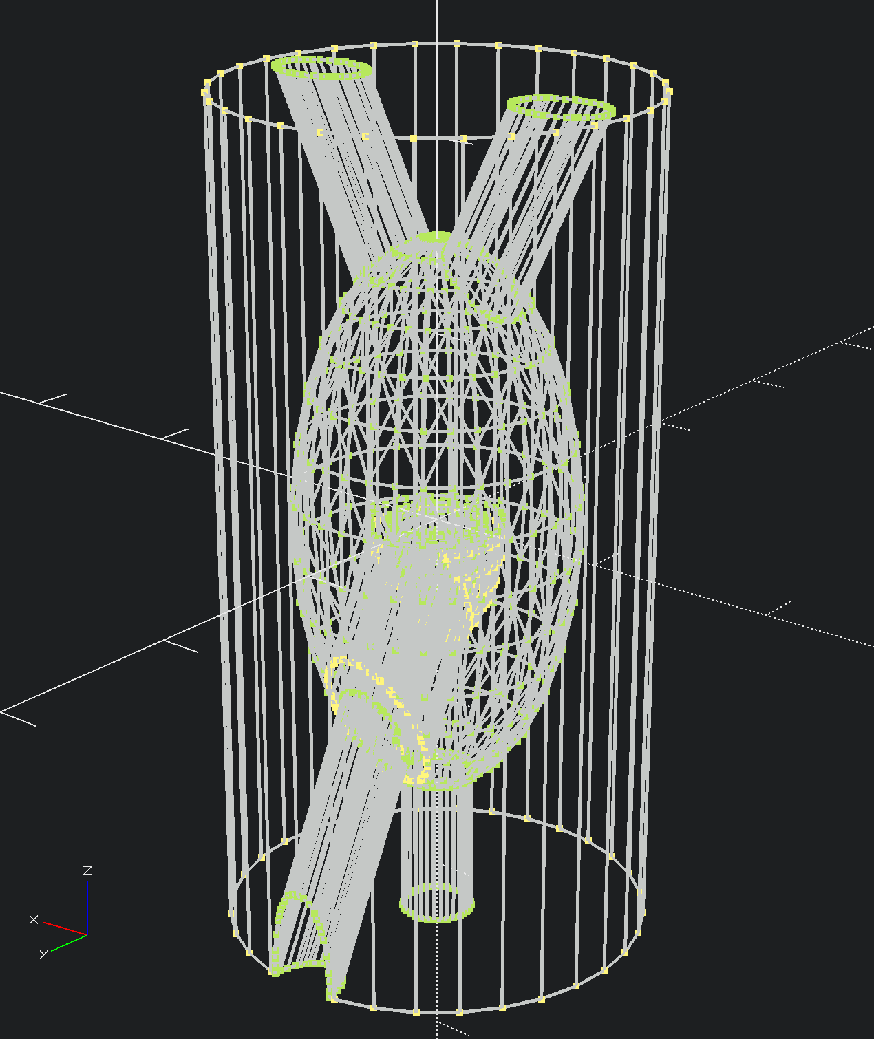
I have printed and tested a small (15mm diameter chamber) of the fluidic half adder shown in the first log entry and it works! If you blow too hard it gets overwhelmed and the XOR terms don't work because fluid just overflows out of both exit holes, however if you blow fairly gently it works great! I want to test on a larger one next and with water hmmm...