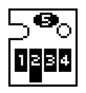
Here's the pin assignment for the PCB:
1 - Clock
2 - Ground
3 - Data
4 - VCC (?)
5 - LED (When this is LOW and 4 is HIGH, the LED is on.)
I'd like to point out that the LED pin might have some other connections since it seems to be pulled high/low without an electrical connection to the printer. However, I haven't been able to confirm this.
 alpha_ninja
Discussions
Become a Hackaday.io Member
Create an account to leave a comment. Already have an account? Log In.