 AKA
AKA-
1Step 1
The assembly of the board is pretty straightforward, except for one thing: the order of assembly. Getting this wrong will mean a bit of bothersome disassembly, because some components sit on top of others and aren't accessible if they're assembled in the wrong order.
The correct way to assemble is to solder all the headers to the PCB first. The plastic part of the header should, in each case, be directly under the daughterboard (the OLED, the EasyDriver, and the Pro Trinket). Here is a photo of the headers in place:
![]()
Getting the headers to stay in straight is a bit of a challenge. I used an extra, unpopulated PCB and some alligator clips to hold them straight; you can see the extra board and how I'm holding the piece in this photo:
![]()
-
2Step 2
Once the headers are all soldered in place, test-fit the daughterboards to make sure you have oriented the headers correctly (ie, the plastic part of the header should be directly under each board, making a spacer of sorts).
Once you are certain of the fit, trim the long ends of each header - the ends that are not sticking out on the side that the daughterboard mounts to. This is important because otherwise nothing will fit. After trimming, you can solder in the boards and the remaining components.
For the encoder, if you are planning on mounting the whole board in an enclosure, you may want to use a short length of silicone wire for each connection, so you can move the encoder to a more ergonomic position on the case.
If you're thrifty and feel you may want to reuse the daughterboards later, they are easy to clip off with flushcutters. To make re-use even easier, you could forego the male headers and use female headers everywhere - this would make the assembly much thicker but would allow you to just pop out any daughterboard as desired.
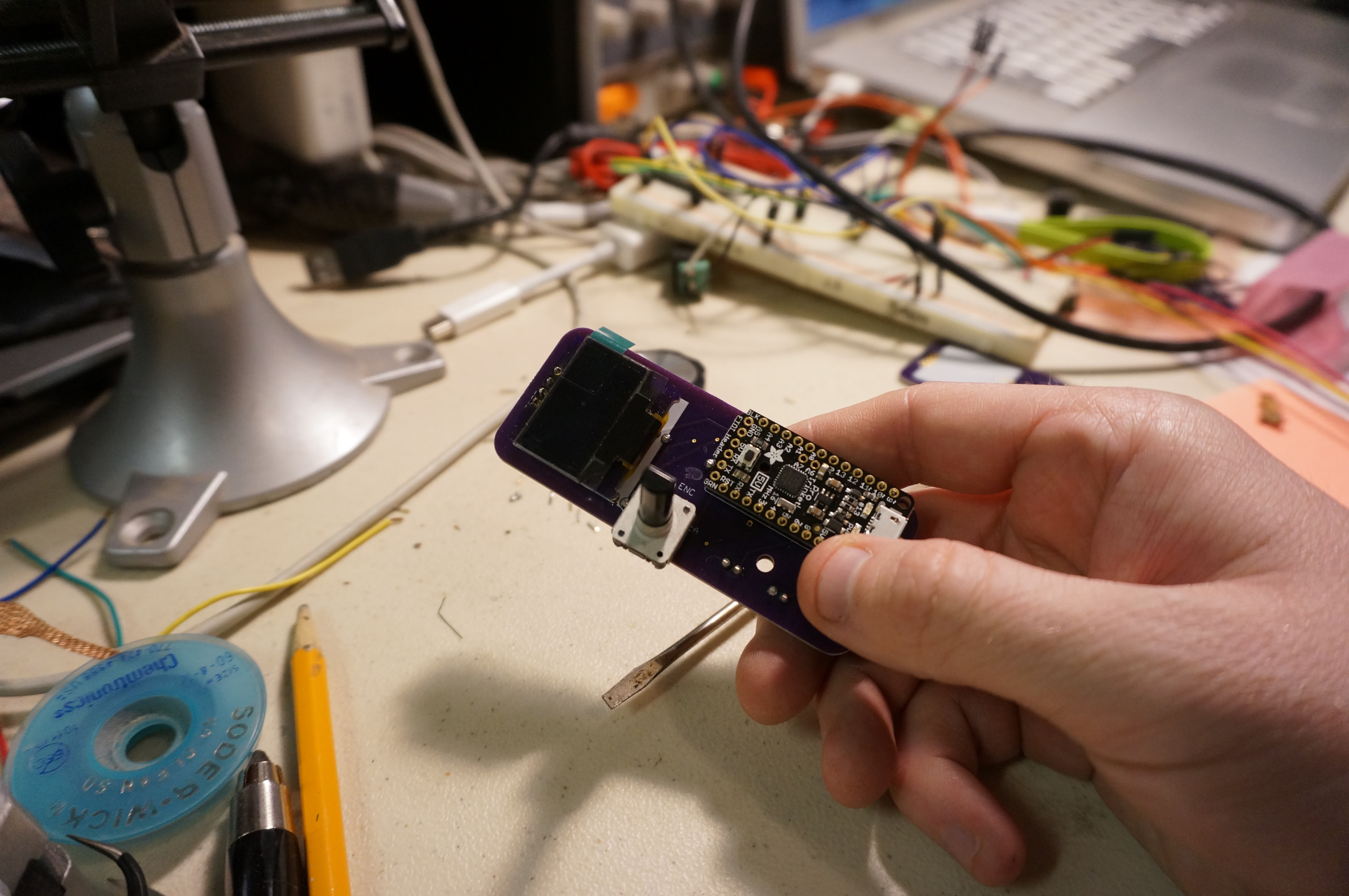
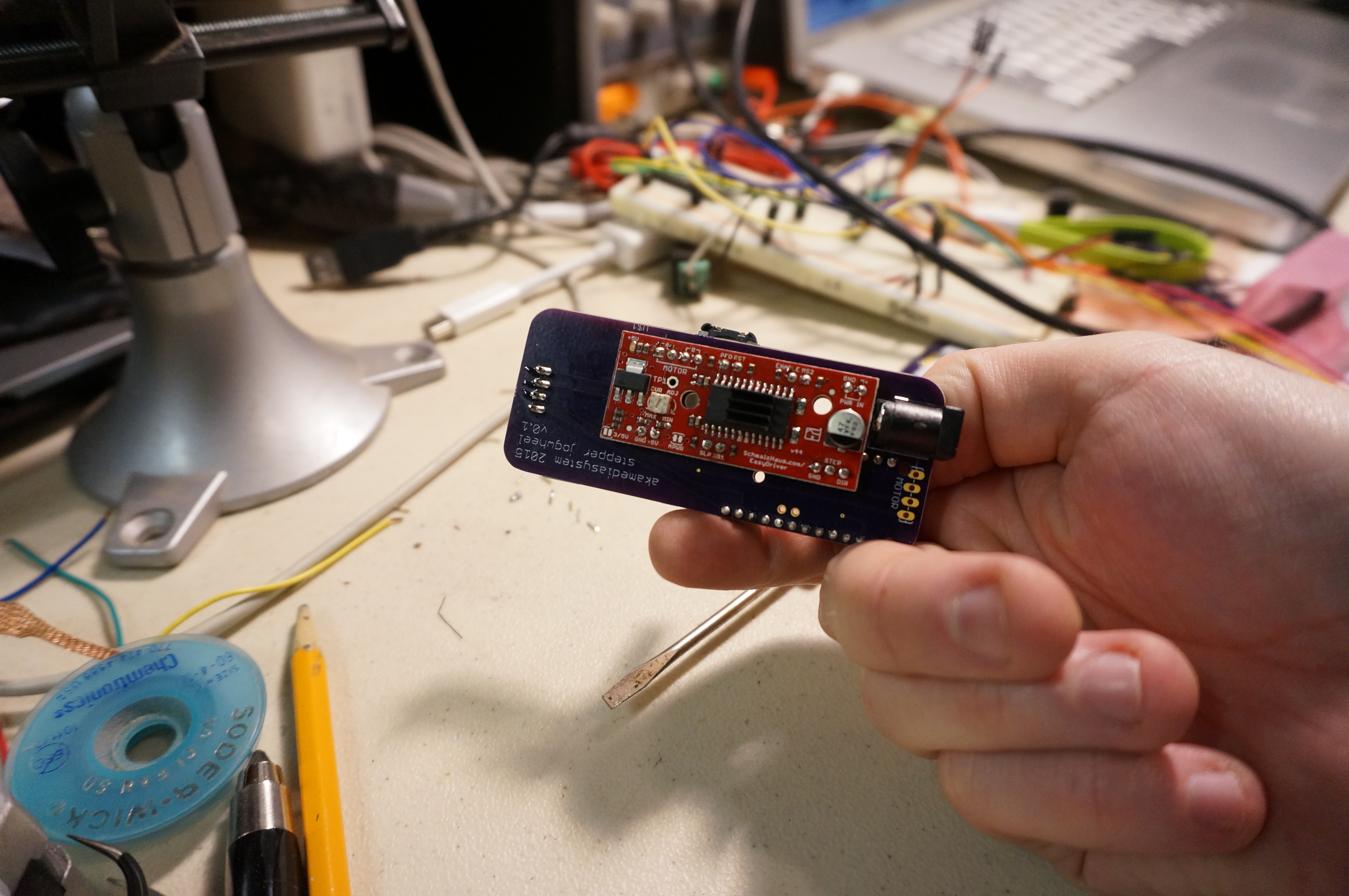
Here are some final assembly photos:
![]()
![]()
Simple jog dial for stepper motor
This is a simple way to adjust the height on the z-axis of my lasercutter; just a jog dial, readout, and stepper controller


Discussions
Become a Hackaday.io Member
Create an account to leave a comment. Already have an account? Log In.