 Eric Hertz
-
Lasers are for wusses. Milling is where it's at!
06/20/2022 at 05:16 • 4 commentsI'm obviously late to the game on this one...
@Paul McClay has gotten high recognition in a previous HaD Prize for his #Minamil: a minimal CNC mill. And friends.
Which, looks to have spawned from his prior *use of* (being more than "experiments with") CD/DVD slides in a CNC mill using a rotary-tool. #CDCNC Nicely Done! Can't believe I hadn't thought of it.
Also, he explains well a phenomenon that could befuddle nearly any aspiring CNC DIYer... Did you know there's such thing as cutting too *slow*?
Check out his work!
-
YES!!!
05/09/2022 at 23:42 • 0 commentsAlthough, my experience with masking tape and markers has been rather impermanent, I'm sure the right tape/pen combo exists.
https://hackaday.com/2022/05/09/all-the-sticky-labels-you-could-ever-need-no-drm-just-masking-tape/
-
First CNCed Toner-experiments
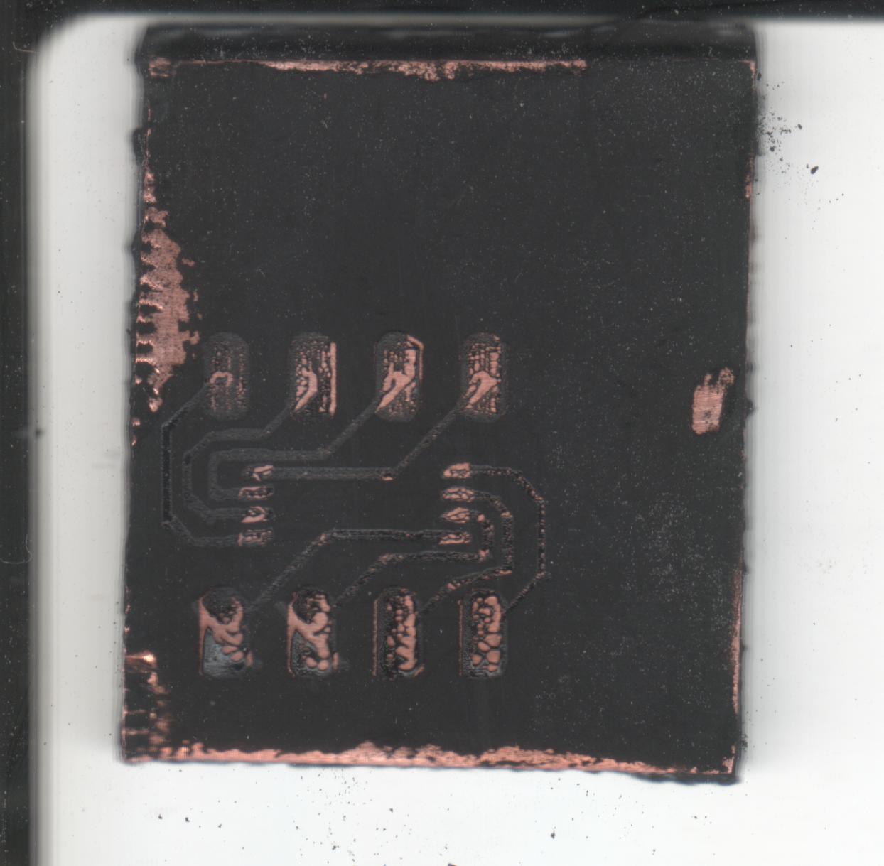
08/01/2016 at 08:02 • 0 commentsThin Slurry Feedrate 30mm/min
![]()
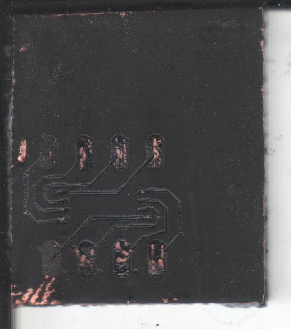
Thick Slurry Feedrate 80mm/min
![]()
The third test-run, Thick Slurry 160mm/min, had about as much improvement in visual quality (fewer burn-throughs, etc).
But, interestingly:
In the second-experiment, wiping up the un-melted toner was easier.. the traces seemed to stay adhered to the copper-clad OK... If I'd've been a bit more careful, they might've even stayed-adhered as all the un-melted toner was wiped-away.
In the third-experiment, the traces actually wiped off *before* the unmelted toner.
![]()
So, apparently, the toner melted to itself, but probably the coldness of the copper prevented it from adhering to it.
Plausibly: Heat the copper to something slightly lower than the toner's melting-point before lasering...?
Though, it seems there's also some importance in choosing a feedrate that is based on the path-taken by the laser... Note the pads always seem to "burn through"
Same feed-rate, but the laser passes much more quickly over these areas, nearly (if not) repeatedly.
![]()
Note that the circles formed at the joint between two traces are *almost* the size of a stepper-step... When the traces are drawn sometimes you'll get two passes side-by-side, or other times you'll get two passes right atop each other... so you can see that when the pads are drawn, it's quite likely there are *multiple* passes on the same path, in the same *step*, which causes the toner to melt more than a single-pass...
![]()
So... either adjust the feedrate depending on what's surrounding, or adjust the laser-intensity... Doable...
Or just find a *really* fine-tipped permanent-marker, add a solenoid, or throw in a rotary-tool, and avoid all these problems :/ But TSSOP with isolation-routing and a rotary-bit? Maybe not... (I still don't own a laser-printer, so toner-transfer isn't an option).
The lasering-toner-method is *really cool*, but it's a bit of work (and mess) mixing up the slurry every time, getting it just right... and when stored for even a few minutes it seems to "settle." Could probably be assisted with a well-sealed container and one of those magnetic mixing gadgets would probably help dramatically... hmm...
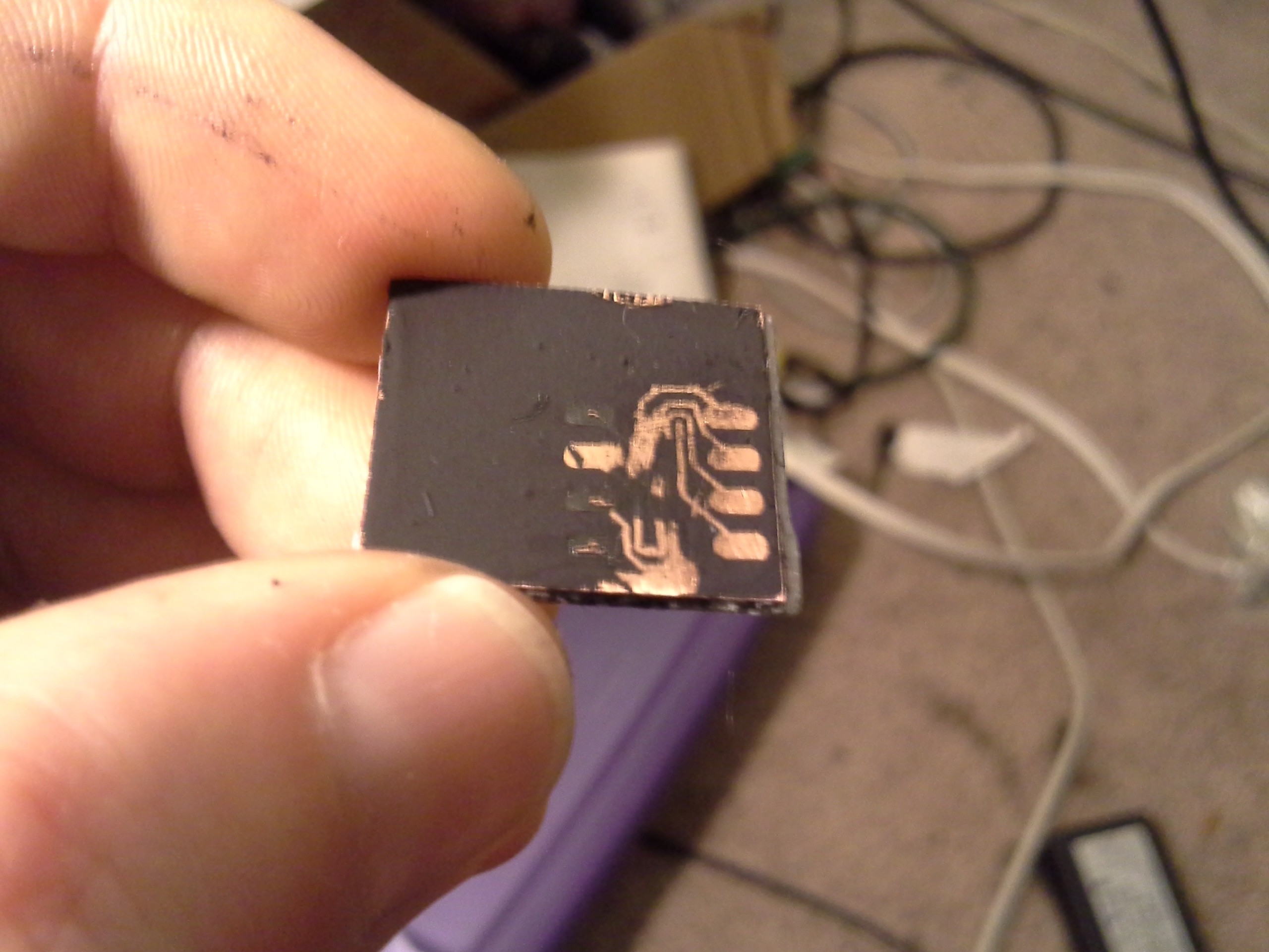
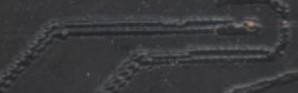
LOL, or shit... maybe I've got it all wrong... Maybe a *really light* pass over the toner, and isolation-routing...? Seems completely backwards, but look again at that image:
![]()
Those traces peeled up *easily* compared to the surrounding (un-melted) toner!
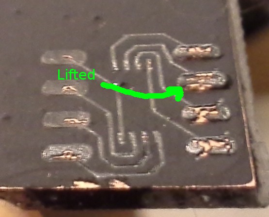
This one started as a strange-accident... I dropped it on the ground, and those pads lifted on their own:
![]()
Hmmmmmmm....
So, then, the idea would be to isolation-route the traces with the laser passing *very quickly* (so the copper-clad behind doesn't heat up), then wipe away the melted-toner, rather than the unmelted toner... Then throw it in the oven for a bit to set the remaining unmelted toner (where the traces are)...
Hmmmmmmmm.....
-
ESOT: Eric Systematically Overanalyzes Things
07/31/2016 at 11:39 • 5 comments![]()
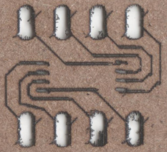
This guy's properly-scaled. HPGL-Settings were a bit off (stupid diagonals through the holes), but otherwise, that's a TSSOP (ATtiny45) to DIP breakout, and it aligns. So, not *perfect*, sure, but definitely doable.
I used a trace-width of 6mils, I measured the beam's burn-width to be 4mils, so I plugged 4mil as the pen-width in Eagle's HPGL output, so it draws each trace twice. This is important, I'll explain in a bit.
This, BTW, is a paper grocery-bag which seems to burn darn-near perfectly every time... Though, with the Pads, the repeated zig-zagging causes it to burn through. That's OK for these early tests.
Got a bit daunted after initially calibrating the system's steps/mm:
![]()
Again with the breaks and overhangs, but this time they're not repeatable! Infact, most of the error is non-repeatable in these (now calibrated) tests.
But then it occurred to me: When outputting a trace-width that's wider than the pen-width, it draws overlapping "sausages." Which might just make up for all those weird "breaks"...
![]()
I tried to take into account the repeatable spacing... 18mils between traces looks pretty good in the spacing-tests, but I ran out of space trying to make this breakout board and just went for it... and the results, again, are much better than I expected. Again, that's a TSSOP... I don't plan to work much smaller than that!
One more time... in case my overanalyzing scared yah off:
![]() TSSOP is fine.
TSSOP is fine. -
More Experiments + microstepping resources
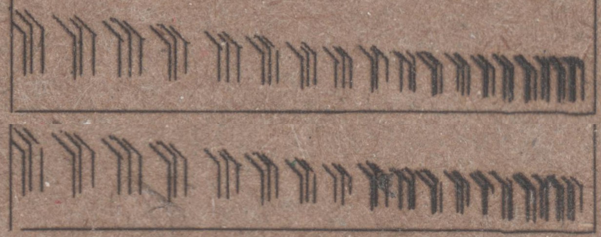
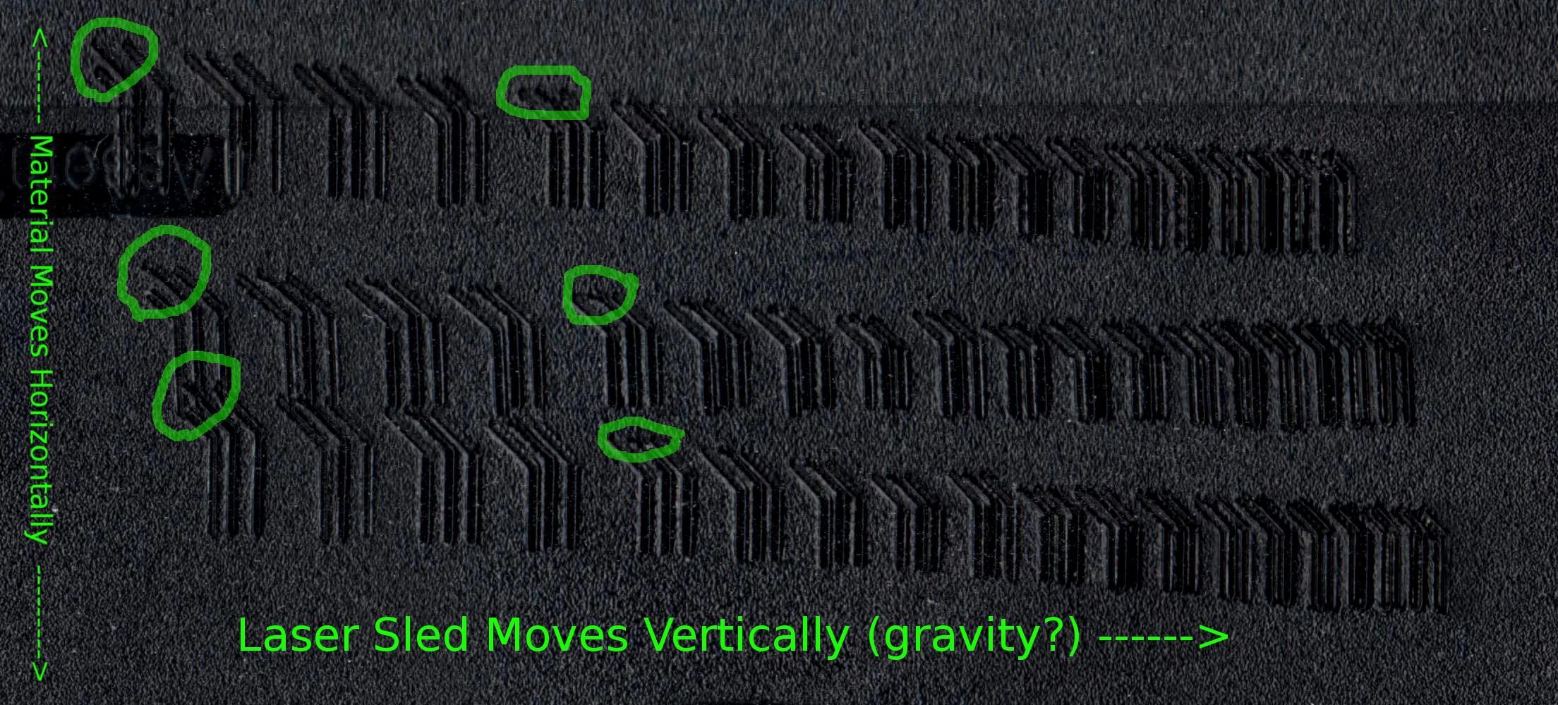
07/30/2016 at 12:00 • 0 comments![]()
The bottom two test-runs are identical settings, just testing repeatability. The upper test-run was after bumping my motor-driver's voltage from 5V to 12V (those motors were HOT).
Click to zoom that biznitch and look at the circled portions. Note that the upper portions of the diagonals are often sloped shallower than 45deg. Why? And note that it's less-apparent (if not non-existant?) when powered with 12V. So, I'm thinking that maybe the laser-sled, since it moves vertically, might be having some gravity-effects which are less-apparent when the motor's got a bit of momentum and also when it's got more power...
Consistency-wise, it seems all three test-runs show nearly identical characteristic oddities in most other cases...
E.G. the uneven spacing of each triad... why aren't those center "traces" centered? And why is it consistent on *all* test-runs...? Am guessing that these are full-steps and the microstepping configuration just isn't strong enough to hold the sled between two steps (but it's OK when moving...?) And, then, wouldn't they have little "tails" from the microstepped position it would've started at when moved to the starting-position, then a straight-line where it settled...? Not seeing that on the perpendicular traces, but it's kinda what I'm imagining to be responsible for the shallow-diagonal-"tails".
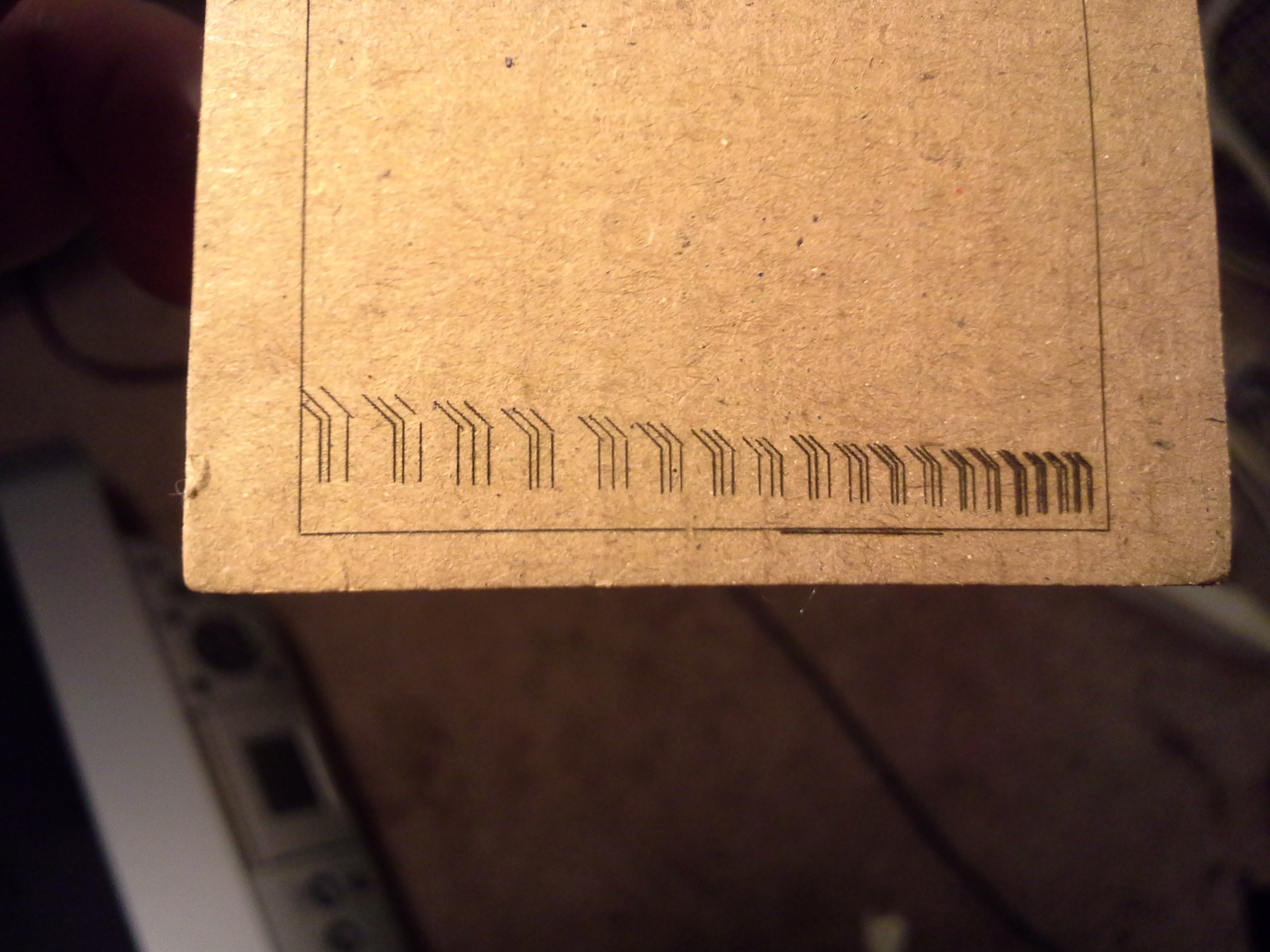
Note also that this test-run (melting into an old floppy-disk) is much more consistent than the original cardboard-test-run...
![]()
I've since done several more cardboard-test-runs, and have gotten pretty flakey results. I think it's *just* past the threshold of actually burning the material, so any differences in the fiber-density, (maybe skin-oils from handling?), etc. would show up as "breaks" in the traces. In several of the re-runs, the majority of the "traces" didn't seem to burn-in at all. (too bad, the smell of burning paper is much nicer than that of burning plastic, and the resolution/contrast is much higher).
And... In the floppy-disk-test-run I don't see the really bad "overhang" on the far-left "triad"... it might be due to the width of the melt, or it may be that the clothespins might've been bumped or otherwise settled during the cardboard-test-run.
(Interesting, I don't see the shallow-sloped-"tails" on the cardboard image... huh. Could it not be a vertical/gravity issue, and instead be a horizontal/momentum issue?)
Also noting the consistency of the triads' bases, which should be aligned. Each of the plastic-test-runs seem to have the same error in alignment... again, likely due to the direction from which they were approached...?
![]()
More analysis to be done...
(Note, again, that my PWM-microstepping method varies the *voltage* not the *current* applied to the winding... So may be a bit less accurate because of it. Also, plausibly, the PWM frequency might be slow enough that it might be effectively oscillating between microsteps at some speeds... hmm...)
I did, however, find some resources suggesting I might not've been too far off in my theorizing about microstepping's accuracy... and whether a two sine-waves is really the most-effective/accurate way to drive 'em... (without feedback)
This is a random-dump of highlights:
Microchip - AN822, Stepper Motor Microstepping with PIC18C452But in practice, the current in one winding is kept con-
stant over half of the complete step and current in the
other winding is varied as a function of sinθ to maximize
the motor torque, as shown in Figure 22.![]()
Never heard of this elsewhere, but it's an intriguing concept.
Microstepping Concepts and Configuration
Motors driven by microstepping drives show non-linearities between full steps. Plotting the desired position vs actual position, where the center of the graph is a full step position, would look like a sine wave rotated about the center by 45 degrees. A full cycle of the sine wave would occur between two full steps.
![]() ...This is caused by the magnetic attraction to the pole that the motor
coils are unable to overcome as well as the way the motor is made.
...This is caused by the magnetic attraction to the pole that the motor
coils are unable to overcome as well as the way the motor is made.
...The repeatability is almost perfect, except for slight hysteresis when changing direction. In other words, when moving to the same position from both directions, the angle is not exactly the same.Right... and that's assuming no load (no static-friction external to the motor, etc.).
If this was consistent across all motors, then I'd imagine it'd be possible to reduce those effects somewhat dramatically by changing the driving-curves a bit to compensate, except the hysteresis factor, and again, the external loading...
Digikey - PSoC® 3 Stepper Motor Control with Precision Microstepping
The position and transitions vary from ideal calculations due to non-idealities in the system such as resistance losses, static friction, and the approximation of the sinusoidal current limits. Microstep resolutions in excess of 16 may not be noticeable due to motor friction and the effects of mechanical error.
![]()
Figure 11: Smooth transitions between steps and limited oscillations and settling in microstep mode.And then some various interesting-things learned... I'll just leave the links here:
Fast vs. Slow Decay: Texas Instruments - Tricks in current regulation when micro-stepping a stepper motor
Holding vs. Pullout Torque: Applied Motion - Microstepping
And this is an interesting way to plot it... Zaber
![]()
"Current Reconstruction" via ADC and PWM: John Figie, Dave Wilson -- A uC Based Stepper Controller using Digital Current Mode Control
![]()
"Mountain Model" and Friction Torque: http://www.sapiensman.com/step_motor/stepping%20motors.htm
Although the ball tries to find it's natural place of rest, friction on the surface prevents it from doing so.
![]()
Figure 15 The mountain modelSome good stuff here, too: Steppers are complicated
-
Bipolar [Single/Micro-] Stepping Thoughts, ctd.
07/26/2016 at 10:49 • 0 commentsAlright, a tiny bit more research...
This is a good resource:
http://www.allaboutcircuits.com/textbook/alternating-current/chpt-13/stepper-motors/
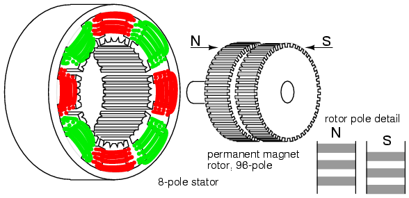
Here's a "Hybrid Stepper Motor" (simplified), (from that page):
![]() (simplified, further:)
(simplified, further:)![]()
"Hybrid stepper motors" are a bit more sophisticated than those in your DVD drive, but they're the ones I've taken apart, so I can understand this one a bit better. These are the big-ol' NEMA# motors used in most 3D printers. They can come in both unipolar and bipolar form.
As far as a bipolar stepper motor, the rotation shown in the second image is acquired by the more-complicated form of single-stepping, described in my last log:
![]() As far as *typical* bipolar-driving goes, this method is less-typical, as it requires more sophisticated circuitry that not only can reverse polarity, but *also* can disable power to the windings. But let's go with this for a second, because, again, this is *much* more closely-related to the typical *microstepping* method used for bipolars.
As far as *typical* bipolar-driving goes, this method is less-typical, as it requires more sophisticated circuitry that not only can reverse polarity, but *also* can disable power to the windings. But let's go with this for a second, because, again, this is *much* more closely-related to the typical *microstepping* method used for bipolars. So, what you see in the image (repeated because... scrolling. Wee!):
![]() So, what you see in the image is the South-Pole of the rotor, and between its teeth you can see the North-Pole which is behind. Note that the teeth on opposite poles are 180 degrees out of phase.
So, what you see in the image is the South-Pole of the rotor, and between its teeth you can see the North-Pole which is behind. Note that the teeth on opposite poles are 180 degrees out of phase. Alright, that's not much different than the simple "bar-magnet" drawing from before. I won't repeat it, here.
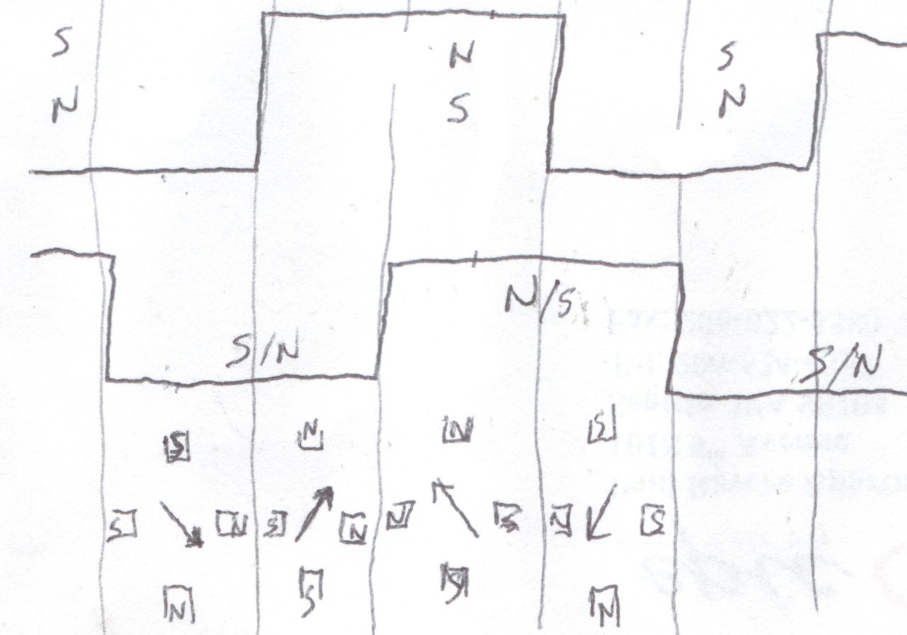
This image shows single-stepping where the teeth of the rotor align perfectly with the powered teeth. These positions are *strong*.
But, here's a half-step:
(This is modified from the original image shown above, from allaboutcircuits.com):
Note that each tooth is only 3/4ths aligned with the nearest tooth on the associated phase-winding... OK, so we've already lost 1/4 of the magnetic holding power just from that factor, alone.![]()
Now, consider that the teeth on the *opposite* pole on the rotor are also now 1/4 aligned with the teeth on the phase-windings. This guy is now pushing back, *against* the phase-winding's magnetic-field. So, I don't know physics to this extent, but I imagine that means it's essentially depleting the overall holding power by something like yet another 1/4th.
So, with my bar-magnet example from the previous log I guessed something like: Put in 2x the power of a single-step (by powering *both* phases' windings, instead of just one) and get something like 1.414x the holding-strength.
And, here, it seems similar might be true... Again, we do have *both* phases powered, this time, rather than a single one (as in the full-steps shown in the original image), so we should have *more* holding-power than single-stepping, but definitely less than double.
Further, when moving from one full-step into the next half-step, we have an interesting scenario where the "other" magnetic-pole is *resisting" that motion. If merely single-stepping, as in the image shown earlier from (a) to (b), *all* the magnetic-force created would go into *pulling* the rotor into its new position. Well, rather, the South pole teeth on the rotor would be pulled to the north winding's teeth (as in (b)) and the North pole teeth on the rotor would be pushed away from the north winding's teeth. So, all the magnetic-force created by the windings goes into moving the rotor to its next step. BUT when half-stepping from (a) to my Half-step image, the opposite poles are acting to *resist* the motion.
This observation isn't regarding the holding-power, but regarding the *moving* power... It would kinda *dampen* the motion... In a way that's nice, it *smooths* it a bit, rather than creating a sudden jerk between positions. But, it also means that now *time* is more of a consideration. Sure, an *unloaded* stepper would eventually wind-up at that half-step, but getting there is a slower process, a bit like pouring syrup rather than water(?).
Then, when you consider external forces, say a spring pulling the rotor counter-clockwise, it's quite likely not only will the motion be slowed even further, but that it might not actually ever reach the "half-step" position, maybe resting more around 1/4th step. OK, that'd be a consideration even with single-stepping. But, now, let's consider other factors... What about overcoming static-friction from (a) to the half-step? What about from (b) to that half-step (reverse-direction). So, now, our half-step might be inclined to go only 1/4th-way between (a) and (b) in the clockwise-direction, and will be located 3/4ths of the way, when "microstepped" in the other direction. What about momentum if the system's already moving smoothly...?
Etc. Etc. Etc.
So, this is where my intuition is telling me that using *sinusoidal* drive-signals for the phases' windings may not be the most effective approach. And, yet, it is pretty much the de-facto method, as I understand. E.G. look at this sophisticated system: http://www.edn.com/design/analog/4368829/Back-EMF-method-detects-stepper-motor-stall (the below image is from there, regarding a dedicated stepper motor driver chip):
![]() This motor-driver chip is designed with microstepping in mind, and uses sinusoidal current waveforms for the phases.
This motor-driver chip is designed with microstepping in mind, and uses sinusoidal current waveforms for the phases.Remember my earlier ramblings regarding the input-power with half-stepping... Wherein we were powering *both* phases at *full power*, and coming up with something like only 1.5x the magnetic force (or less?)...
With actual microstepping techniques, at a half-step, we'd have sin(45) = sin(45+90) = .707x the power output by the motor-driver and going into each winding, so rather'n double the full-power going into the system (vs a single-step), we now have 1.414x the power going into the system, and that, again, is reduced in magnetic-force due to teeth-alignment between attracted-poles to something like 3/4... giving roughly 1x the magnetic-force... Which, would be great, darn-near-perfect (if efficiency's not a concern), except again that doesn't account for the fact that the same polarity-teeth--which are aligned by 1/4 with the same-polarity phase-windings--are *resisting* that motion, and further pushing back even when in steady-state.
This sinusoidal microstepping technique seems to be treating each [micro] step as a steady-state, and further, neglecting the half of the system.
Now, that chip is allegedly "programmable" wherein maybe they plan for other more sophisticated waveforms... I've yet to see anything regarding what those waveforms would look like. Maybe my initial guess of something more like a tangent-function is a bit off-kilter, maybe something more like a sin^2? But, still, such a system would be treating each microstep not as a *motion*, but as a steady-state...
...so, still some intuiting and searching to be done.
Oh, right... and none of this is to say anything about the types of steppers used in a DVD drive, which are quite a bit different, in design (and plausibly in functionality at this level?).
![]()
-
Bipolar Single-Stepping Thoughts
07/25/2016 at 06:50 • 0 commentsThe sled-motors in most DVD-drives are usually Bipolar Stepper Motors. These are stepper-motors with only 4 wires (whereas Unipolar Steppers usually have 5 or 6 wires).
In a bipolar stepper, the wires are paired-up to electromagnet-windings. But the separate pairs are not connected to each other (again, unlike a unipolar stepper).
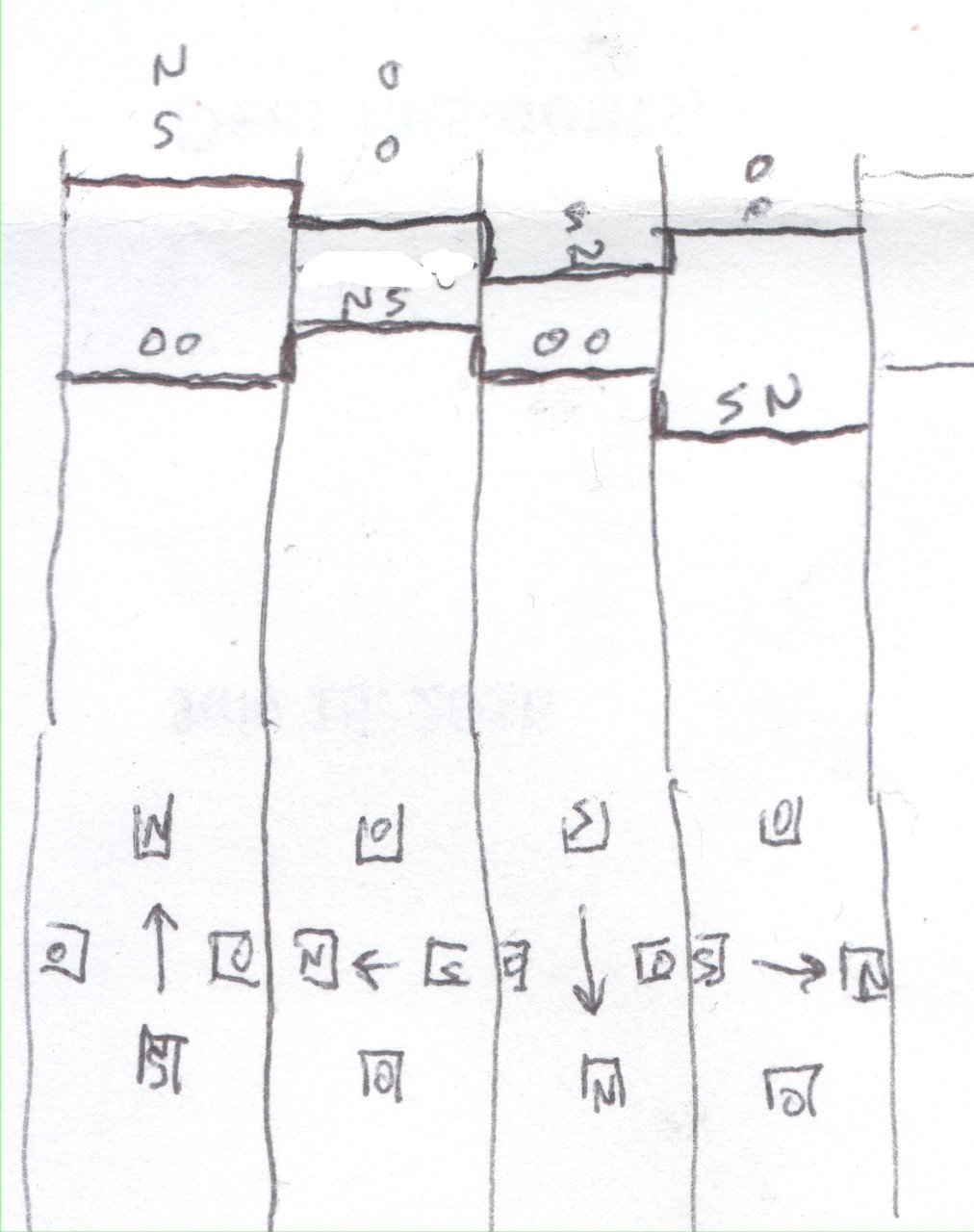
One way this is often viewed is thusly:
![]()
So the motor's shaft is attached to a fixed-magnet with North and South poles, and opposite electromagnets are paired together.
Right.
So, it might be apparent from that picture that for this simplified motor to rotate 180 degrees, the polarity of the horizontal-windings must be reversed... Thus "bipolar" requiring the voltage applied to the windings to switch polarity in order to create motion. (These windings are often called "phases").
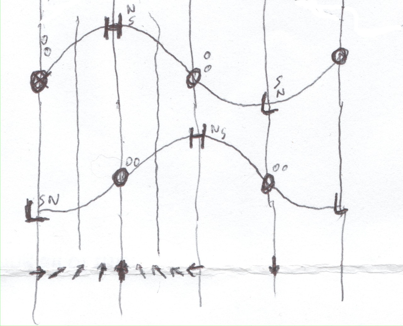
Now, as I understand, the typical way to drive a bipolar stepper with "single-stepping" is to use two square-waves 90-degrees out of phase. Quadrature, essentially.
![]()
(Where the upper waveform applies to the "vertical" electromagnets, and the lower waveform applies to the "horizontal" electromagnets).
The "shaft" in this case is shown similar to a compass, its fixed-magnet is pointing North.
The waveform shown causes this motor to rotate counter-clockwise. The upper waveform "leads" the lower-waveform, its rising edges occur first. To reverse the direction, change which waveform "leads" and which "lags."
Alrighty, looks pretty good.
Except, look again at that first picture.
![]()
Notice something about that "compass"? It consists of, essentially, a bar-magnet.
Now, in this picture, that bar-magnet is *strongly* attracted to the horizontal electromagnets because its surfaces are *really close* to the surface of the electromagnets. Remember magnetism is much weaker in air than in a magnet (or metal)... The less air, the stronger the attraction.
So, revisiting the two cases:
![]()
Because of the small air-gap, we have a strong attraction to the rotating-magnet between the single powered-winding/phase on the left, and we have a weaker attraction to the rotating-magnet between either of the * two* powered-phases on the right.
The image on the right, again, is the way "single stepping" of bipolar-motors is often implemented (again, using Quadrature).
Interestingly, as I understand, when both of the winding (pairs) are powered-down, and the shaft is turned by-hand, the stepper-motor will have a tendency to "step" between steps shown on the left. Because, again, when the windings themselves are powered-down, the magnet on the shaft will be most-strongly attracted to the metal in the windings, rather than the air-gaps in-between them.
So, already, when using quadrature, "single-stepping" is, in effect, already suffering many of the difficulties introduced by "micro-stepping."
I dunno the math (and physics) off-hand, but basically if you're applying 2x the power (1x power to each phase) then you're achieving something like only 1.414x the effective strength of a single phase's being powered. AND, if I understand correctly, that's *neglecting* the tremendous effects of the increased air-gap.
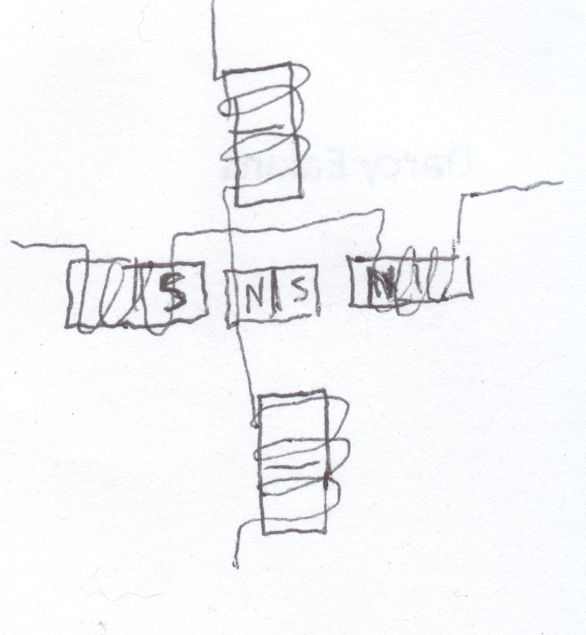
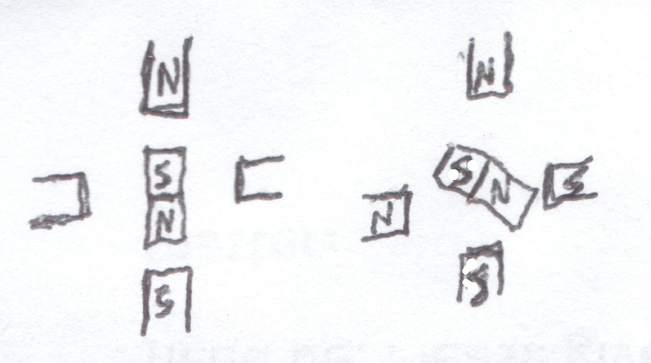
There is another way to power the windings, rather than using (digital) quadrature. And, still, this would be considered "single-stepping." In fact, I'd consider this *more* "single-stepping" than the other method, as it actually stops at the steps where the motor would stay if it were unpowered.
![]()
Note, now, the magnets on the shaft are most-strongly attracted to the powered phase, because the air-gap is small. This, however, requires a bit more logic (and circuitry) than the typical "[digital] quadrature" single-stepping; it requires a phase to be either positively-powered, not-powered, or negatively-powered. AND, the "1x power" described above is likely weaker (though much more efficient) than the "1.414x power" described earlier.
So, where do we go from here...? Electromagnets aren't particularly efficient, right? Throwing more voltage at 'em will result in more heat. If the stepper's rated for 5V, and bumping it up to something like 7V (or higher?) to achieve the same strength, we'll get a bit more heat, as well. Too much heat can melt insulation on windings... so it's not ideal.
ON THE OTHER HAND: This method is *much* more like the simplistic "microstepping" technique of driving the two windings with *analog* sine-waves that are 90 degrees out of phase.
![]()
However, again, consider the air-gaps.
I can't fully wrap my head around it, at the moment, but if that gap has as much influence on the holding/positioning strength as I'm imagining, I could vaguely perceive that instead of 90-degree out-of-phase sine-waves, we might actually need something more like *tangent* functions, 90 degrees out of phase(?), to achieve the same holding-force at any given position.
Further-still, I can vaguely perceive there may be motor-configurations that differ functionally from the simplified example usually given.
Now, I've been known for having pretty bad search-fu (ever since they got rid of operators and wildcards), but I've never seen any explanation for micro-stepping other than sine-waves...
So, apparently, the intuitional-search--rather than the internet-search--continues.
Now... this kinda boggles my mind, as "Brushless DC Motors," which really aren't that much different from stepper-motors, are allegedly becoming as ubiquitous as they are... I can understand their use in situations where *speed* is a concern, (they probably found their initial-niche in spinning hard-disks or CPU fans) but I'm having a *really* hard time believing they're as-common as being alleged for *positioning* without some extremely sophisticated feedback loops, excessively high voltages, and high-resolution position-encoders. In which case, frankly, there needn't be much understanding of the physics, as much as there'd be a need for high-speed DSP algorithms that could neglect those physics as much as they wish by merely accommodating the unexpecteds rather'n trying to expect them. Which, too, would require power-systems with *much* higher capabilities than the typical ratings of the windings. We're talking... e.g. your 12V DC-motor might be replaced with a "12V" BLDC, but for positioning-purposes might require spikes of 48V or more. This practice isn't uncommon for stepper-motors... single-stepping can be dramatically improved by sending a voltage-surge way higher than the rated voltage, then immediately dropping that down to the "normal" range. Doing this allows for a bit of overcompensation for the windings' inductance, which resists changes in current (and thus resists changes in electromagnetic force). So, by over-powering/volting the winding briefly, the current, and therefore force, can be changed more quickly, which kinda makes sense as far as "microstepping" and changing a motor's micro-step from one to the next. But, then, there're all sorts of "stepper drivers" which seem to be completely oblivious to the actual specifications of the motor, claiming to have 16 or 256 microsteps, which really don't amount to anything more than the amount of overall power applied to the windings, which again, really has no meaning, especially if those [micro] steps are occuring at different rates or from different directions, or are in any way loaded by static/dynamic friction, momentum, or other external forces... nevermind differing motor designs.
Quite frankly, I find it extremely surprising that stepper (or BLDC) motors are able to achieve what they allegedly do... I could understand in a highly-engineered situation wherein it's very well known that the stepper's resolution is *way* higher than necessary (e.g. through gear-reduction) as well as it being known that the stepper's *torque* is *way* higher than necessary at any speed that might be required of it, then it makes sense it would work... (in which case, "microstepping" serves no *positional* benefit, but definitely serves a benefit toward its ability to move from one step to the next smoothly without being *loud* in doing-so, and plausibly aiding in its ability to move without missing a step). But people be throwing steppers at things that allegedly work, with zero consideration of these factors... How? No Friggin' clue.
I do know that we once needed a custom gear overnight that was cut via stepper-motors which we were unaware until the next morning lost steps the entire way through the process... That was a friggin' mess that resulted in countless calls to gear-manufacturers until one just happened to be cool enough to do a custom-run overnight for our needs and an overnight delivery, for free, no less... and if I wasn't so friggin' stupid, and the team wasn't so friggin' frantic, we'd've made a tremendous effort to thank that company and the dude who was so gracious as to take our call, work extra hours, and bring it to the attention of the supervisors to get us that custom gear from halfway across the country in two days. Fsck steppers... That Dude and his supervisor are great blokes. Makes me proud to be Murican.
-
Resolution Experiments and flow...
07/24/2016 at 13:19 • 0 commentsTonight some resolution-experiments...
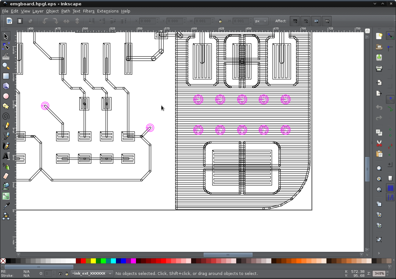
I used Eagle for the first time since college, what, a decade ago? (Holy snap, how long has there been a Linux version?) And one nice thing I discovered is *really* good HPGL support.
Note the paths used to fill the pads and fill-layers... it also fills wide tracks, and even pays attention to "pen"/tool-width. Awesome.![]()
(PCB design from #Mumai, written-up recently on the blog.)
I'm using grbl. (I'd intended to use HPGL from the start, as I've already done motion-control projects with it, before... but that's another story. And the PC-side grbl tools are pretty sophisticated these days, what with rendering, etc.) And that means I need to convert that HPGL output to G-Code. And low-and-behold the friggin' search-fu finally worked in my favor... "hpgl to g-code" resulted almost immediately in exactly what I needed! Howto PCB from Eagle - RepRapWiki
Cool.
(Note that most G-code (and similar) output from PCB applications seems to be aimed at mills/routers, which cut the material surrounding the traces, rather than drawing ink (or toner #Mini PCB printer!) where the traces are located, as I'm doing).
OK. So, Eagle -> HPGL -> hpgl2gcode (requires python3) -> G-Code -> Universal G-code Sender -> grbl -> stepper-motors.
The output of hpgl2gcode is quite straightforward (as is the HPGL), so it's not difficult to modify the Z-movements into 'spindle' start/stop commands, if you're using the 'spindle' output to drive a laser, as I am.
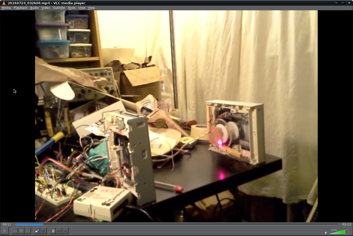
Yes, that's cardboard, and yes the laser burns some cardboard... especially with slower feed-rates...![]()
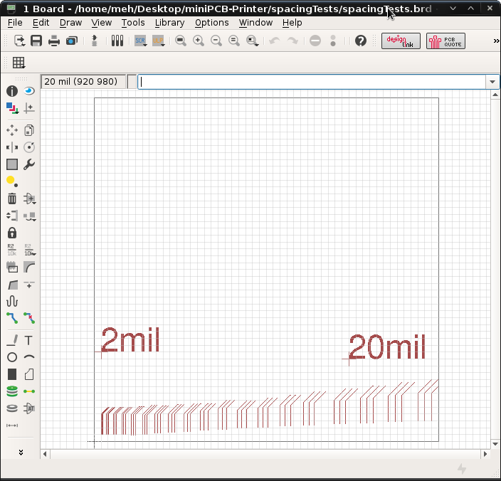
Here's the PCB layout...
Three traces parallel spaced at 2mil to 20mil (1mil traces, 1mil pen-setting in HPGL).![]()
Drawing the text was pretty slow, so I ultimately removed that from the raw gcode.
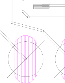
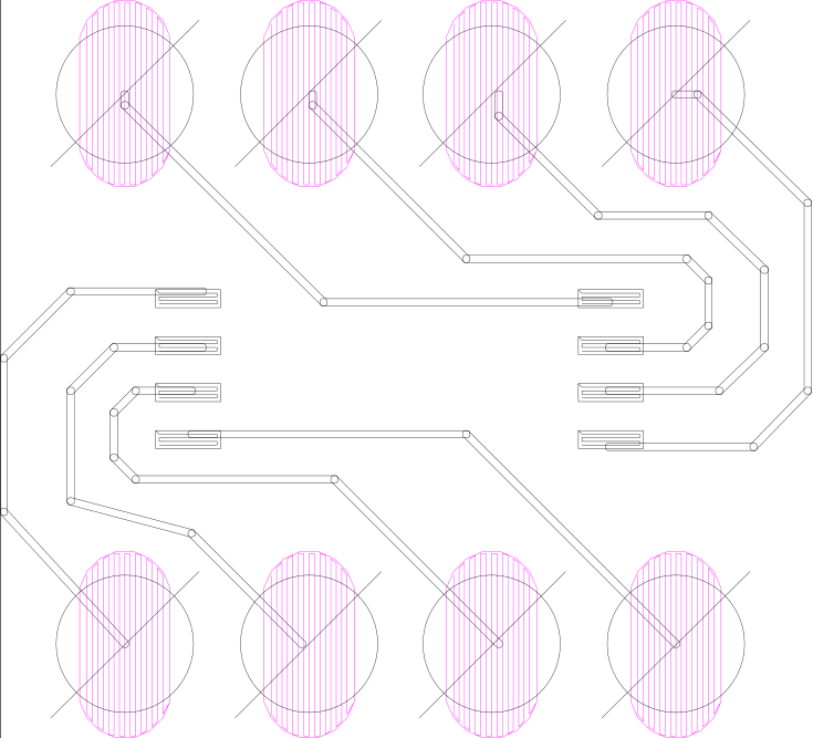
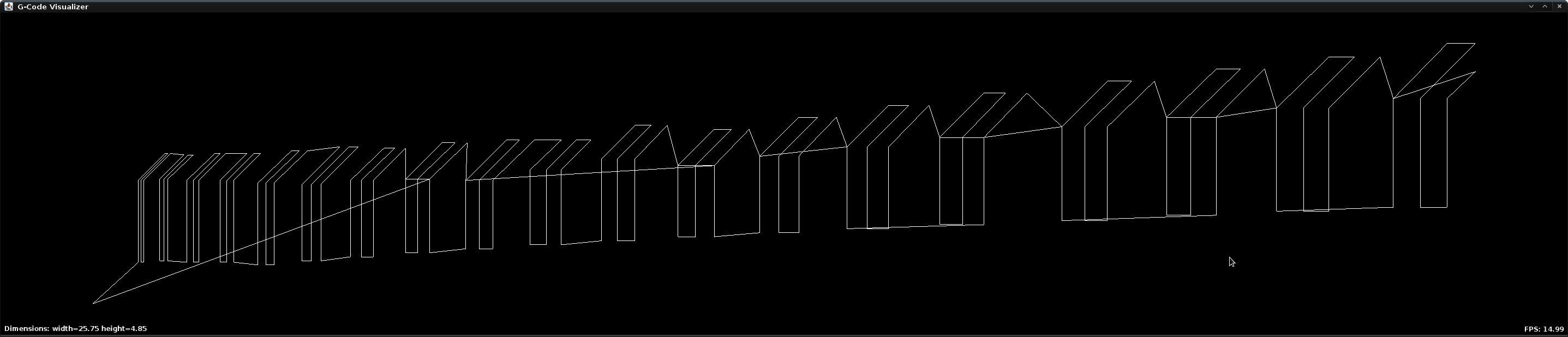
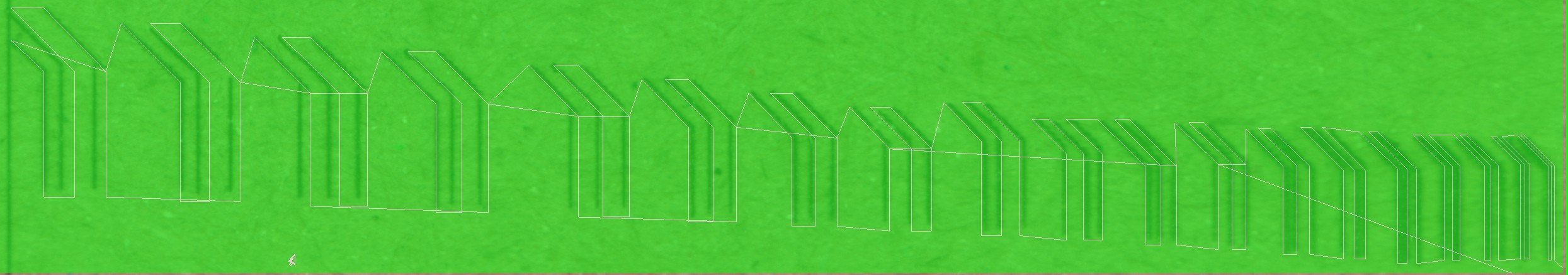
Here's the visualizer from the Universal Gcode Sender (UGCS) (a *very* nice feature, that definitely makes conversion to g-code worthwhile even if you have a device capable of HPGL):
![]()
Interestingly, it doesn't draw all the paths in the same direction, guess it's trying to save time as best as possible. Also, though, it turns out to be a handy test of the precision of the system...
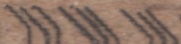
Here's the cardboard:
At first it looks darn-near awesome... but upon closer inspection it's easy to see some odditites.![]()
Yeah, I could expect some breaks, likely due to the cardboard fibers varying in various locations, rendering it more difficult to burn... But then there's some overlaps, and those ain't right. Then there's the traces which clearly aren't evenly-spaced... and that ain't right either.
So, I thought, hey, there's a lot of conversion going on 'round here... Who knows where it's coming from, but I can easily think of conversions from floats to ints, then back to floats, then back to ints, and probably even more. So... maybe... And then there's the fact that my PWM-based "microstepping" is pretty much non-sophisticated, but we'll come back to that.
So I spent *way too much* time trying to get a side-by-side between the actual output and the rendering... And discovered many flaws in my thought-process along the way.
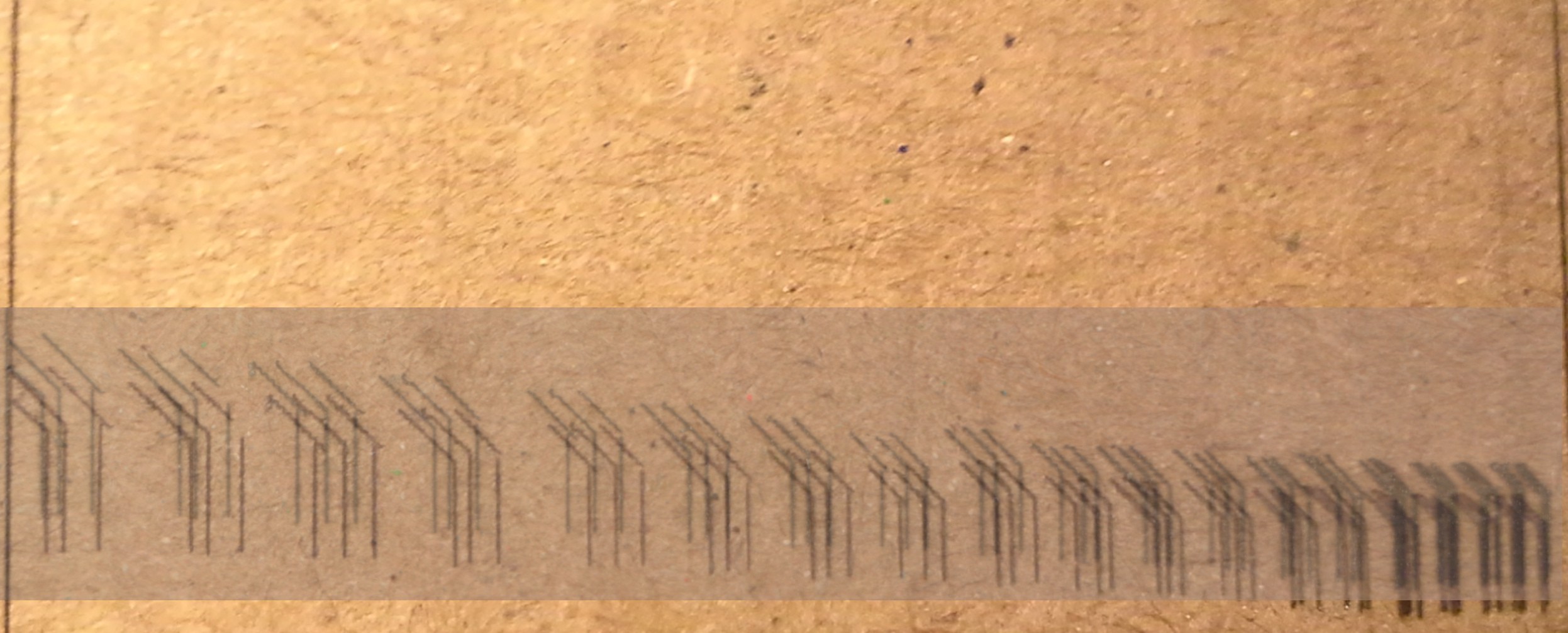
Big One: cameras taking close-ups distort the image. Below is a scan (from a flatbed scanner) overlayed (and slightly shifted upwards) atop the photograph:
Note how the two line-up at the edges, but in the middle they're quite far off. Makes sense, but took quite a while to figure out while comparing the photo directly to the rendering. Won't bother showing that. (Oh, yeah, and apparently one of my steppers is wired backwards).![]()
Here we have the rendering compared to the scan:
Kinda hard to see, there, (are there click-throughs to zoom? I forget).![]()
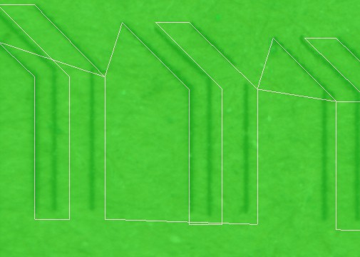
Here's a highlight:
You can clearly see the path to be taken by the machine (in white) isn't exactly consistent for each trace... But the points do all align. So, it appears the most-visible errors aren't due to all those conversions. There must be some error in the software (which I modified) running on the machine, and/or with the steppers themselves.![]()
So, that might make sense, considering I modified grbl to add direct PWM-based microstepping output... microstepping isn't *particularly* accurate, anyhow. And my implementation could probably stand to be improved.
Note some other "features"... there's a distinct jagged-pattern on the diagonals. That'd make sense if single-stepping.
It would also make sense in poorly-implemented microstepping... The motors really do want to hold at certain positions more than fractional-positions, so it takes more energy to move away from a step to a microstep than it does to *hold* at that microstep (overcoming the motor's tendancy as well as external forces). So, it would *also* make sense that there might be some *slop* which varies depending on which direction it approaches each fractional-step. Which might explain some of those "overhangs" etc., many of which appear to be almost exactly one "step" (comparing to the stair-step pattern).![]()
...So, maybe it's best to stick with dedicated motor-drivers with step/dir inputs (rather'n H-Bridges), if you've got 'em, or money, or patience waiting for delivery... none of which are on my plate ;)
Thing is, the traces in that furthest-to-the-left group are separated by 20mils, and off by quite a bit. Worse-still, I haven't calibrated the machine, which means that those are more like 30mils! Also, those overhangs are bad, and the opening is even worse... So...
(hmm, is it just me or are those 'stair-steps" longer than they are tall...? I wonder if gravity has anything to do with this?)
Oddly... I don't recall that much error on the earlier tests which were *much* more complex...
![]() Note that this guy was drawing each line *twice* (except for those weird rounded-insides of the wrenches which I can't explain). But maybe if it drew them from the same direction each time (I'm not sure) then it would be less noticeable...
Note that this guy was drawing each line *twice* (except for those weird rounded-insides of the wrenches which I can't explain). But maybe if it drew them from the same direction each time (I'm not sure) then it would be less noticeable...So, I'm not sure.
One plus: That "trace width" is looking like about 7mils, as best I can figure out how to measure it with my calipers.
-
DVD-Lasered Jolly-Wrencher
07/14/2016 at 12:26 • 2 commentsThe moment We've all been waiting for... Or at least I have.
![]()
Not sure why Inkscape decided to draw every line twice, something about edge-detection? And where'd it get the curves in the wrenches? Dunno.
USE GOGGLES, and Open The Window. That be burning-plastic smoke you see in the video.
Grbl has been hardware-abstracted and ported to PIC32, per the last log. Also added direct-support for PWM-microstepping output within grbl, to be fed directly into H-bridges, rather than the normal "step/direction" output usually fed into an EasyStepper. (The PWM output is a sine-wave fed into the two windings, 90degrees out-of-phase).
Other tools: Universal G-Code Sender (java-based), Inkscape with the Gcodetools extension, (Inkscape CNC (G-Code) tutorial - YouTube), Grbl, 2 DVD drives (the burning-laser is, I think, from a 20x drive, running at 250mA, just remove the focussing lens, and the focal-point is about a foot away),
-
grbl + usage-TODO?
07/13/2016 at 07:51 • 0 comments(Update: Adding this link: https://github.com/ericwazhung/grbl-abstracted/tree/master)
So, nowhere in these logs is information about using grbl...
Over the past countless weeks I've been working up to using grbl... Why so long? Well, for one I don't have any unused AVRs with enough pins/memory to load it on. So I've been working on porting it to my PIC32s.... And today I've accomplished motion, for the first time... more on that later.If you don't know what grbl is, as, believe it or not, I didn't only a few months ago...
grbl is software you can run on a microcontroller to accept G-code (CNC commands) sent from a computer, and convert that into motion via stepper-motors.
As I recall, back in the day, using G-Code to control a CNC-machine meant running a Real-Time Operating-System (such as RT-Linux). So, I guess, what makes grbl special is that it offloads the realtime aspects of the motion-control to a microcontroller (usually an AVR), then the host-computer only needs to send high-level motion-commands (e.g. "move to a point") via serial-port whenever there's enough buffer-space on the receiver. No real-time stuff necessary... run it from any computer with a serial-port, or USB-to-serial converter.
The cool thing, I guess, is that it's *really well supported*. I mean, seriously, check out this page: https://github.com/grbl/grbl/wiki/Using-Grbl
OK, that's that.
There're some things I've learned along the way, the hard way, that I haven't seen explicitly-stated elsewhere... e.g. the limit-pins don't seem to have any effect unless you *enable* them, so if you don't [have the knowhow/patience/pins to] wire-'em-up, you can still get a system running likely without even having to modify the code...
So, notes like these, I wouldn't mind being written-up somewhere. (if someone knows a link, by all means, lemme know and save me the trouble!)
Alright, so I've been working on porting grbl to my PIC32s.... And today I've accomplished motion, for the first time.
So here's some big TODONEs:
Hardware-Abstraction
Everything other than the EEPROM has been abstracted to the point of macros and function-calls that can be written for nearly any architecture... I've obviously done it for PIC32, and the original AVR code has been moved to *_avr.c/h files. The architecture can now be selected in the Makefile, and it will include/compile the *_<architecture>.c/h files as appropriate.
EEPROM/No-EEPROM
The EEPROM stuff is, frankly, a bit excessive... It's easy to do on devices (like an AVR) with an EEPROM built-in, but many microcontrollers don't have it. One alternative is to implement it in FLASH (read/write an unused portion of program-memory). That's doable on most architectures these days, but it is *very* architecture-specific, and I didn't have the patience to do it for PIC32. Another alternative is to use I2C or SPI EEPROM chips... Again, pretty hardware-specific. Could easily be done, but wasn't within my patience-level. The Alternative I chose was to make an option for NO_EEPROM. In this case the system acts as though it's brand-new/unconfigured, thus using default/hard-coded values, each time it's booted. OMG... 'cause, frankly, most people probably don't change those settings anyhow. And, they can easily be changed in a source-file if necessary.
Byte-Identical!
Despite all the above hardware-abstraction functions/macros, it can still be configured to compile BYTE-FOR-BYTE identical to the original grbl-master compilation. This is KEY, as, as I understand, grbl has been *well* supported for quite some time. Doing all this hardware-abstraction results in *zero* changes to the original functionality... Even additional function-calls would result in changes in terms of context-switching, pushing/popping the stack, etc. This configuration-option shows that even despite *all* the hardware-abstraction, there's NO CHANGE to functionality, speed or otherwise. And, thus, it's easy to see what changes have been made, (when the Byte-Identical test is disabled) in order to debug, if necessary, when implementing new architectures.
NEW FUNCTIONALITY:
PHASE-OUTPUT:
Rather than outputting Step/Direction signals, those pins can now be used as PHASE-outputs, to directly-drive H-bridges which in turn directly-drive the stepper motors. This is a relatively minor change... If it weren't an add-on, it would probably require *less* resources than the step/dir outputs. But, in keeping with the knowledge that grbl has been known-functional for quite some time, it makes sense to add this as a sort of additional (software) "peripheral" atop the already-functional code.
PHASE-OUTPUT + MICROSTEPPING:
The next step, after that, is microstepping. If your microcontroller has enough PWM pins, it's only a small step to add direct control of H-Bridges WITH microstepping (via PWM). This is, obviously, implemented for PIC32.
So, as it stands, I've a PIC32MX170F256B, which has a sum-total of 28 pins... it's a bit short as far as running a Z-axis, but it's plenty for a 2-axis/laser/router system. And... it's running! With microstepping... and no "easy-steppers," just some old dual-H-bridge chips extracted from some floppy drives.
https://github.com/ericwazhung/grbl-abstracted/tree/master
More to come, I'm sure... It gets a bit wonky, as this "project" is relevant to so many others I'm working on, so notes might end up in those logs instead....
CD/DVD mechanisms and cartesian thinggie[s?]
DVD-laser-etcher, dremmel-router, possibly a 3D printer? Who knows!


 ...This is caused by the magnetic attraction to the pole that the motor
coils are unable to overcome as well as the way the motor is made.
...This is caused by the magnetic attraction to the pole that the motor
coils are unable to overcome as well as the way the motor is made.


 (simplified, further:)
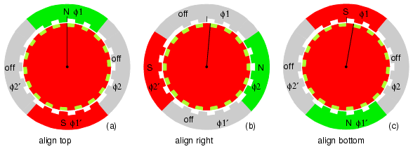
 As far as *typical* bipolar-driving goes, this method is less-typical, as it requires more sophisticated circuitry that not only can reverse polarity, but *also* can disable power to the windings. But let's go with this for a second, because, again, this is *much* more closely-related to the typical *microstepping* method used for bipolars.
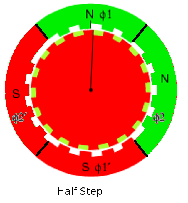
 This motor-driver chip is designed with microstepping in mind, and uses sinusoidal current waveforms for the phases.
 Note that this guy was drawing each line *twice* (except for those weird rounded-insides of the wrenches which I can't explain). But maybe if it drew them from the same direction each time (I'm not sure) then it would be less noticeable...