Eric Hertz
-
PCB FAB?
12/11/2015 at 10:57 • 8 comments@Stefan Lochbrunner and @esot.eric were thinking about using a dvd laser to ablate spraypaint for making PCBs as seen <here>. I had a laser working, but whether I tried paint, marker or tape, it just didn't work right when the stuff was stuck to copper.
Taking apart a few laser printers, I struck on the idea of using toner - it's a plastic powder that melts on, and is what people have used for making PCBs at home.
I tried dusting on the toner powder, but that failed epically. But I did eventually find a method that works!
1) Mix some toner in with some alcohol (water doesn't work due to surface tension and this dries faster anyway). It shouldn't be pasty, but you do want it quite thick.
2) Clean some copper clad board with steel wool or whatever, then pour on some of the toner mixture. Tilt the board to get full coverage, then shake off the excess. Watch someone doing tintype photography to see a professional at getting the constant thickness. As you're shaking it off, the stuff left on the board should already be drying. Give it an extra blow or two and you're ready to laser!
3) Use a DVD laser (mine is in an XY thingee outlined in other posts) to burn out the pattern of the traces. You may have to experiment with different burn speeds, focuses (its good when not quite focused) and coating thickness (varied by adding toner the the slop) to find what works.
4) Carefully use cotton wool or a soft brush to clear away the non-melted toner, leaving the melted toner where you want.
4b) Heat the remaining toner and the board above some sort of flame to fix it thoroughly in place.
5) Etch away the excess copper and you should (theoretically) have a board! Yaay :)
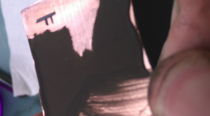
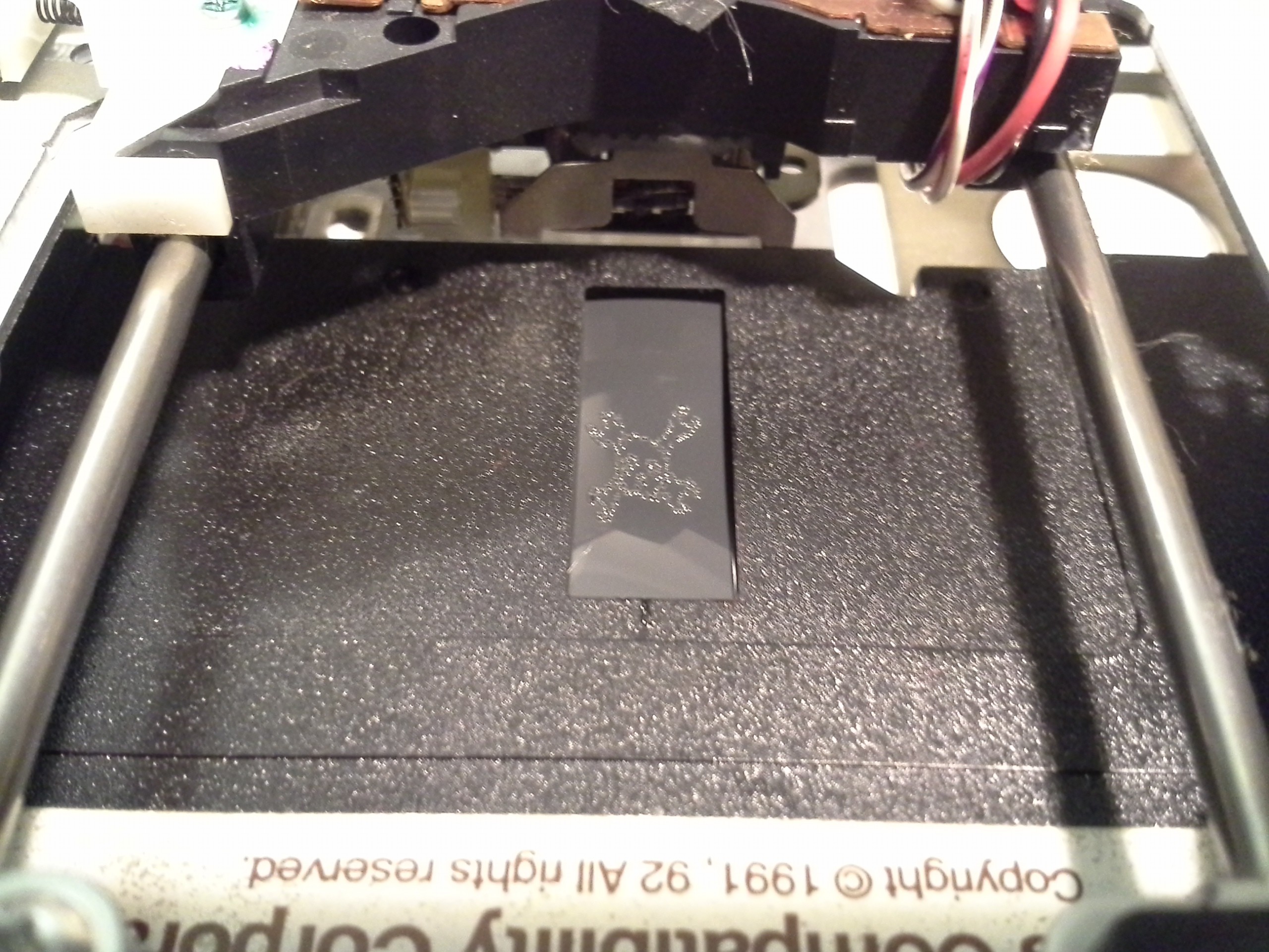
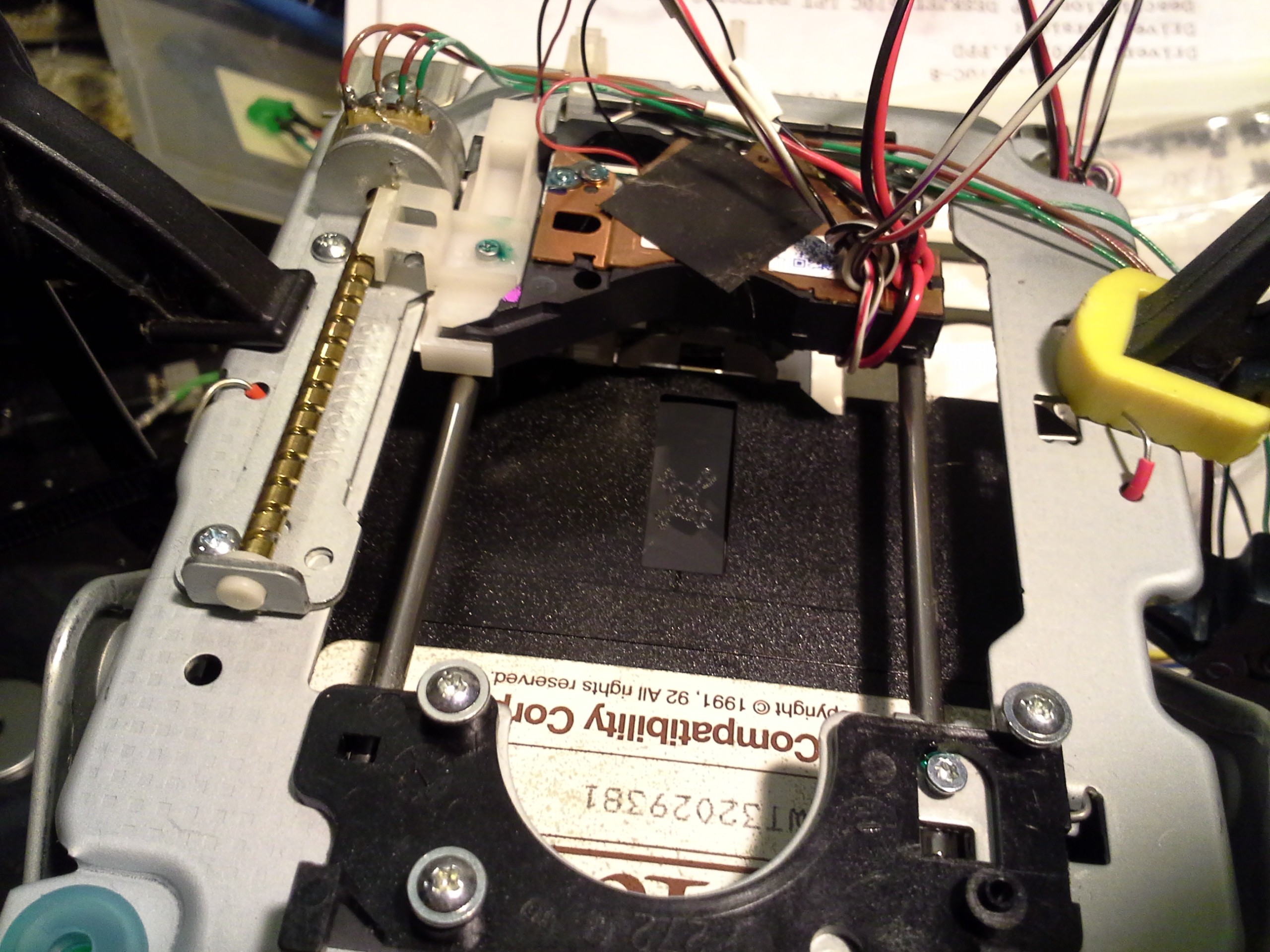
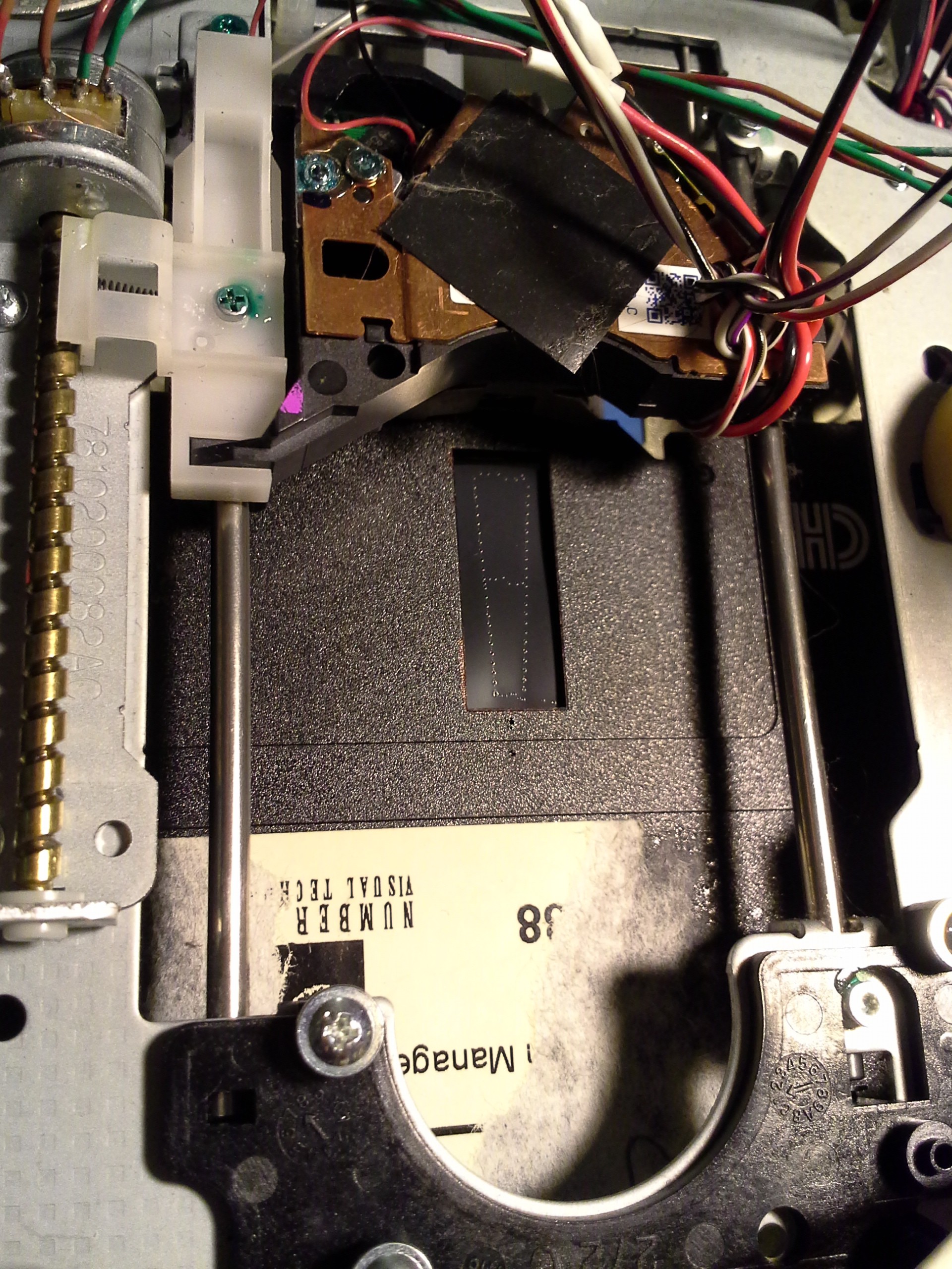
Here's a test trace (not etched yet). I could scratch it off easily, but careful handling should help (edit - problem solved by 4b).
![]()
__UPDATE 1__
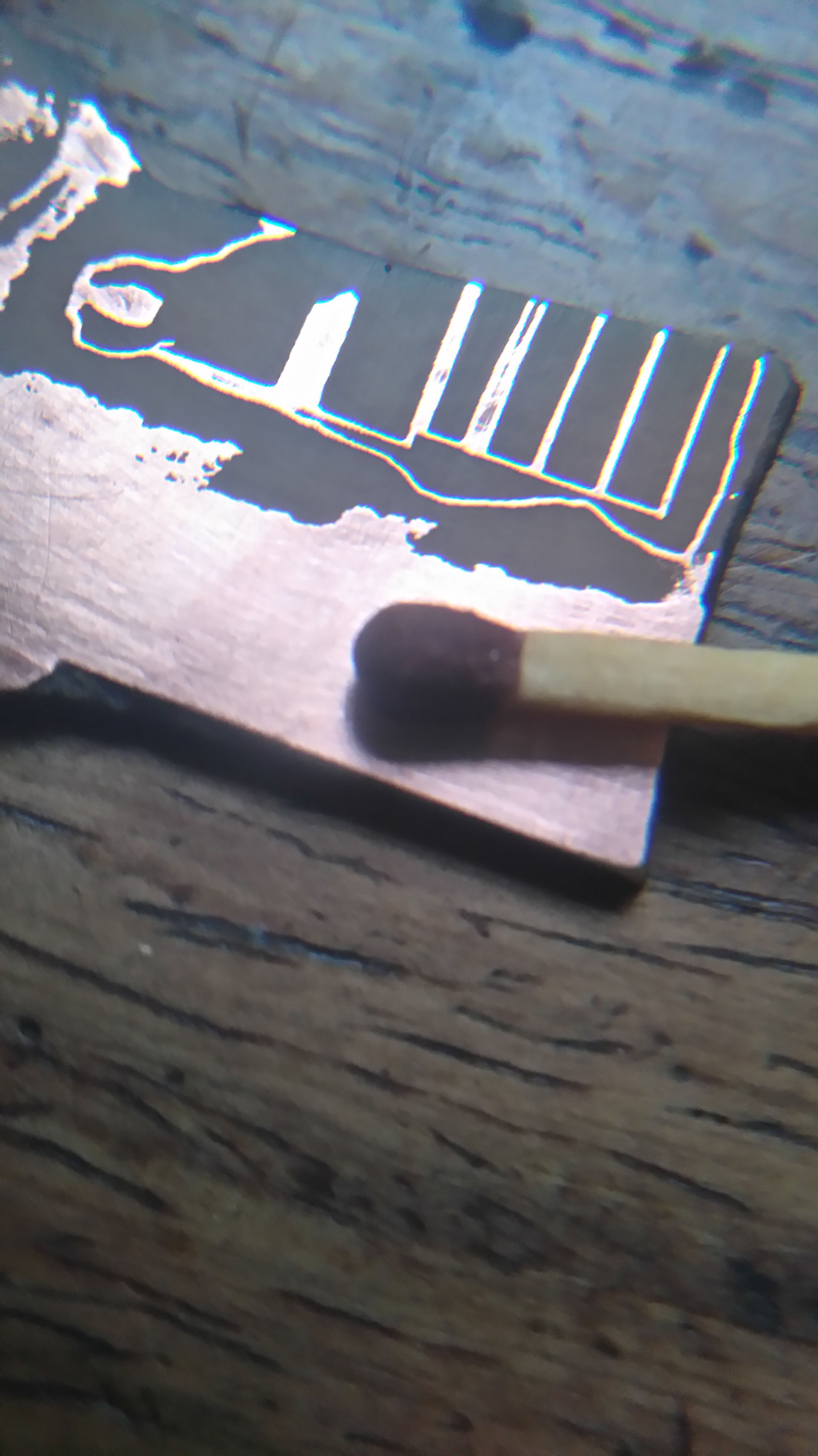
I'm leaving on holiday but just had to try properly. The video files are massive, and I don't have time to edit/upload yet. Here's a money shot of the results though:
![]()
I added a step between 4 and 5 above, which makes handling the board without the traces lifting much easier. In fact, they survived harsh scrubbing without a single break. So this is good to know if it is going to be a silkscreen method.
I confess to speeding up the etching process with some VERY strong HCL, but don't even think of trying that without gloves+goggles+safety tie. Seriously, I happily splashed the H2O2 in my eye and bleached my fingers a little with it, and people normally freak out about the safety of that. So when I freak out about this acid, you know it's bad.
I am amazed at the tiny track width this thing manages. And the clearance between lines it can achieve! It looks like there are some broken patches in the photo, but these are left over toner.
Even though this was just a fake pcb sketched in inkscape in 5 mins, I am pleased with how this is looking and excited to try some actual boards in January, plus show the whole process in a video.
Happy hacking!
-
Laser Diode mA vs. mW misunderstandings in previous logs!
12/11/2015 at 03:41 • 0 commentsI believe I've made some horrendous mistakes in my mA vs. mW understanding/explanations on previous logs!
This probably explains why many of my burnt-diodes were burnt!
Prompted by @johnowhitaker's explanation at: https://hackaday.io/project/560-mini-laser-cutter/log/28767-getting-there/discussion-42620
Here's the bit that I think might've been horrendously-misunderstood/mis-explained throughout previous log-entries, so please read the corresponding tidbits in those entries with a hefty amount of skepticism!
P = V * I. Duh.
I've burnt-out a LOT of diodes in this project, and having only a couple remaining drives with lasers allegedly-capable of burning materials, I need to figure this out...
So e.g., as I recall, I think I configured my original current-source to drive my 16x diode with 200mA, per something I read online... That diode, on that circuit, has yet to burn out, but *several* later diodes on my new circuit *have*. Including 16x (and a 20x?) diodes. The new circuit is nearly identical to the old circuit, except for one plausibly-glaringly-related thing: I actually calibrated its current-limiting resistance (calculated: 5ohms) until the output actually reached 250mA (for a 20x diode) when the potentiometer was at its minimum.
According to a chart in these logs, copied from elsewhere, according to one particular diode's specs: "x16 speed recording – 250mW".
BUT: P=V*I...
And, I haven't been measuring the voltage! Let's just say that the forward-voltage of the diode is somewhere around 2V...
P = V I = 2 * 200mA = 400mW.
Somehow, I think, I was making the mistake that 200mA would equate to something *less than* 200mW, not *MORE*. I guess I had something like P=I/V in my head for this case, or maybe I was taking the mW-rating to be *optical* instead of *electrical*? Something like that. Regardless, somehow I figured 200mA would be a safe value for a 200mW diode, 250mA safe for a 250mW diode, etc. CLEARLY THAT'S WRONG. P=VI. Duh.
So, why has my 16x laser-diode survived on the old circuit, when so many others on the new circuit have met their demise...? Because, in part, I think, I never actually measured the current output from the original circuit...I threw in the calculated resistor-values (and a potentiometer, in series) and let it go... and had no trouble.
OTOH, with the new circuit I went to a lot of trouble to make sure the maximum output-current was what I expected, which meant quite a bit of calibration.As I recall, I started with two ten-ohm resistors in parallel... 5ohms, right? Then I measured the output-current which was something quite a bit less than 250mA. They were 5%ers, so I found a resistor to put in parallel that should've been about right to fix the tolerance-issue... That *still* wasn't getting 250mA, so I found *yet another* resistor to put in parallel...
Finally I got 250mA, which I figured should be well-within-spec for a 250mW diode. (But of course P=VI. Duh.)
Now, here's another thing...
The circuit contains a potentiometer in series with the (now "calibrated") current-limit-resistors. I think I used a 100ohm potentiometer... Well, it's quite likely that those 100ohm potentiometers have a bit of resistance in them, even when adjusted all the way to the "0" end...
Then there's the equation for the current-output of the LM317 current-source circuit:
I ~= 1.25V / R
Right, so R = 5ohms = 250mA...
But R = 6.25ohms = 200mA
So all it would take is 1.25ohms of error to *completely* change the output-current... 1.25ohms on a potentiometer-wiper ain't much, right...?
So who knows.
It's also plausible that the calibration I did, by placing resistors in parallel with the (5ohm, calculated) limiting-resistor actually resulted in a much *lower* resistance. Maybe my potentiometer wiper wasn't adjusted *all the way* to the left when I did that calibration. Or maybe the wiper had some dirt on it, so now with my "calibrated" limiting-resistance values the output can spike during adjustment... I dunno.
Lots of speculation. But the key is it wouldn't take much in terms of tolerance-error in this case to bring a calculated-but-unsafe current to a physically-safe value...
And thus, I've a 16x diode that's been running on a half-assed and mistakenly-calculated circuit for quite some time, and a graveyard of diodes from a carefully-calibrated circuit whose output was being watched almost constantly.
I guess tolerance-error worked in my favor on that first one.
-
Newbie, his setup and THE SUN!
12/10/2015 at 12:31 • 0 commentsSo I (Johno, Yenrabbit, that other ginger dude, whatever) joined the project. Without further ado, here is what prompted me to join:
![]()
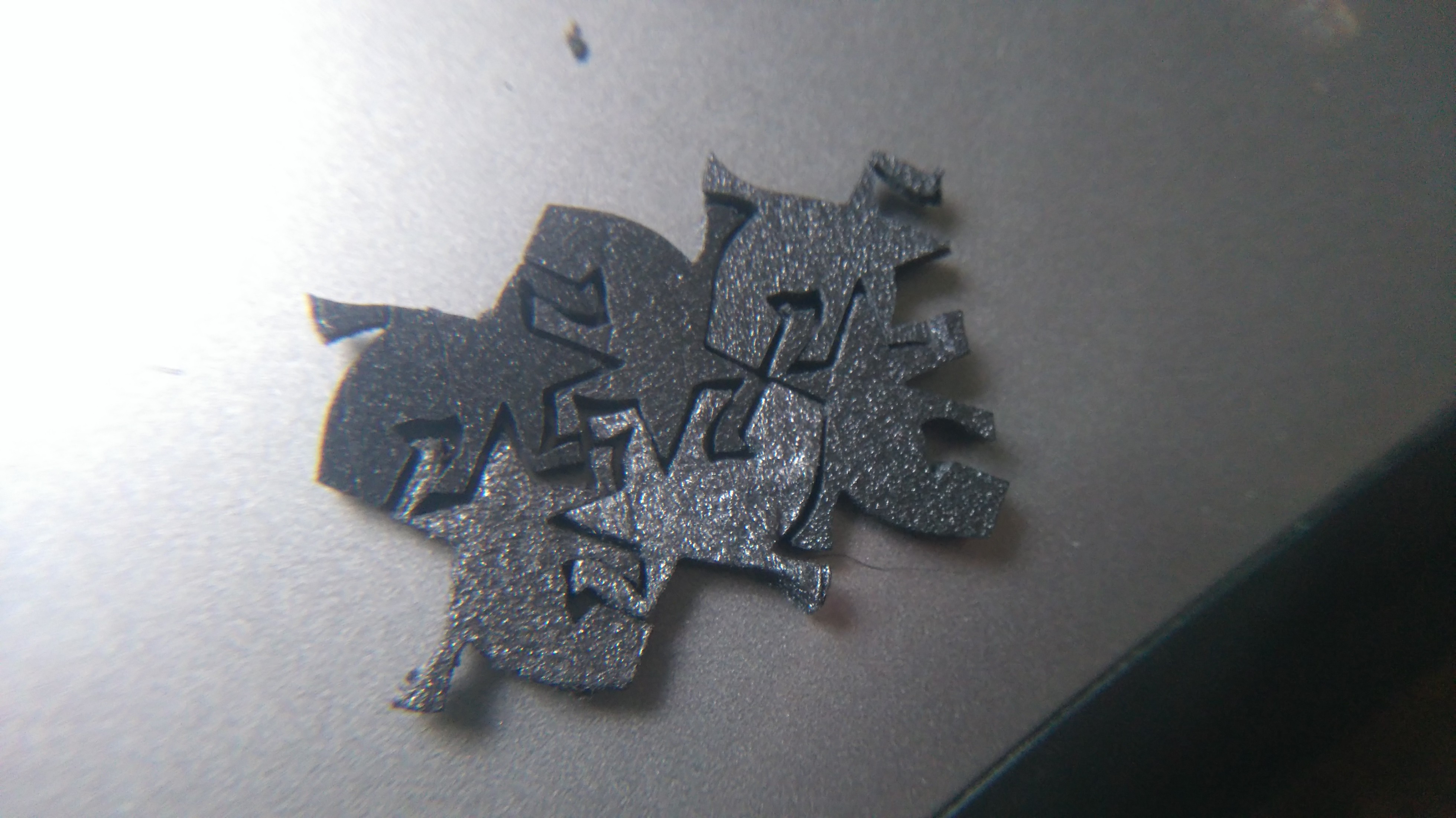
(https://hackaday.io/project/560-mini-laser-cutter) And a sample cut through polystyrene:
![]()
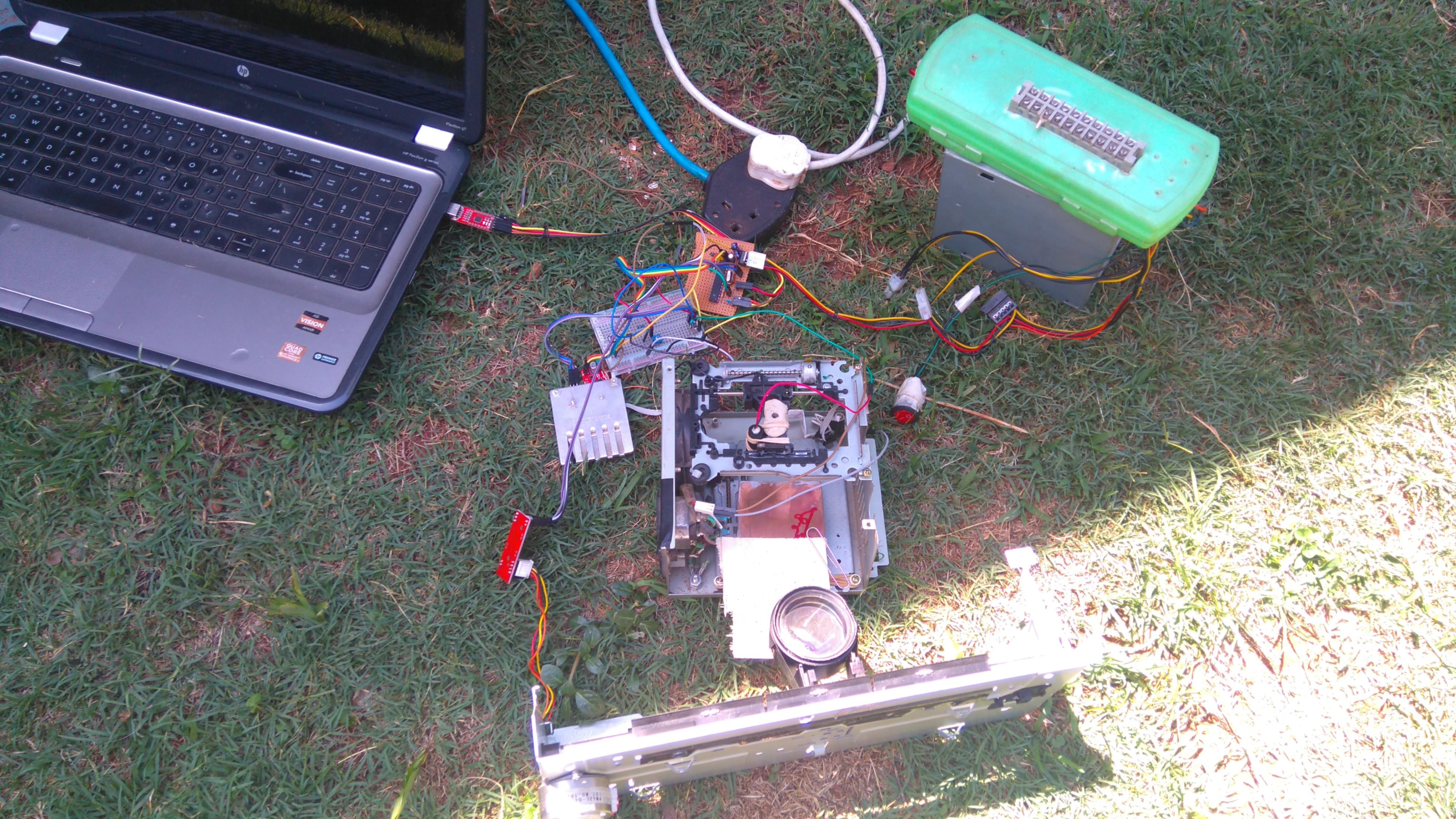
There are two DVD drive sleds, mounted at right angles inside an old power supply, both stepper motors driven by easydrivers and an ATmega328 with gbrl firmware to interpret gcode. A 500mW laser being (under)driven my an LM317 based laser driver and some fluff for the fan etc round out the setup.
I also have a larger axis from a printer which I can swap out for one of my sleds. To test an idea I taped a lens to it and tried to harness the sun to my will. My nose probably got more burnt than the wood - precision and grass+electrical tape do not go together!
![]()
I think that about wraps it up for my introductory log. I have a few more steppers lying around from a laser printer I destroyed yesterday, and I am hoping to dig up a few more drives soon, so hopefully more hacks to come :)
![]()
-
More Experimenting, plus pictures from yesterday
11/14/2015 at 13:15 • 4 commentsHere's the first-go at a rotary-tool "chuck"... I described it quite a bit in yesterday's log. The end-result was, my tools just aren't precise enough to make this work. There's way too much "wobble", and unfortunately a bearing on the second shaft just doesn't seem to help.
![]()
It's mostly due to not having the right drill-bit size, which required widening by-hand, which is just not very precise. The bit's shaft is actually not at all coaxial with the motor's. No amount of bending the coupler would align 'em... If the bit's parallel to the motor-shaft, then it's offset.
(Also, the bolt in the picture was a nice find, a self-tapping bolt! I used it to tap the set-screw holes, worked great!).
I tried a second-go with similar results. Maybe I'll try again, and plan to have a bearing at the bit, but that's on the back-burner, due to drill-bits.
Here's the new design:
![]()
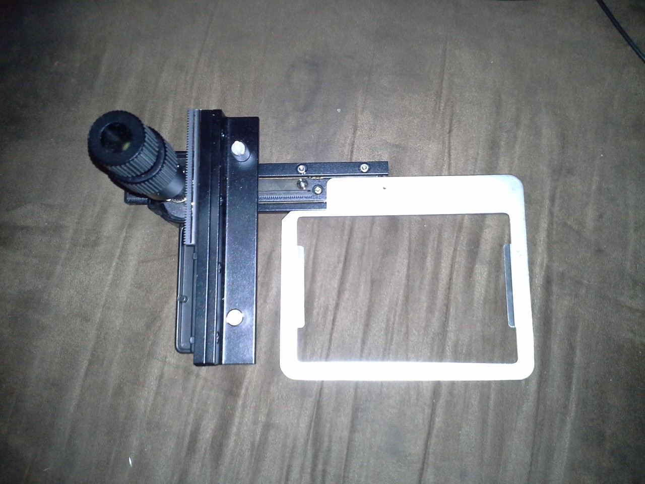
This new motor is *much* quieter, plausibly at the cost of speed. But it's also geared-up... Did some test-drills with a PCB and it seemed to *drill* fine, routing is another issue.
Two bearings are zip-tied (for now) to angle-stock, at either end of the bit's shaft. The third bearing (these bearings are actually from pulleys, I left the pulley on the third bearing). The third bearing prevents the bit from riding up and down. This is a quick-test, thus the zip-ties and cheesy support for the third bearing.
There's a new problem, now... These bits are *tiny,* just small enough for spaces between TQFP pins (nice!). BUT, they're *drill* bits, meant for plunging, not for side-cutting. I've broken four or so of these today, alone.
So, one consideration is possibly doing several *really shallow* passes, and I built a test-rig to try this out (see below).
Also, heat... I dunno why it didn't occur to me, but it came to light with the test-rig... those bits can get hot! I'm not sure whether the heat I felt would be matched with *really shallow* passes, but if it's close, I'll have to worry about whether the rubber-belt will hold up to it. That's another consideration for later.
Here's the test-rig:
![]()
I mounted the PCB on the really sturdy axis right under the rotary-tool (this is the axis that might eventually support the tool) and did several passes in a straight line.
Not the best test-rig, by any means, but certainly better than trying to hold the tool in one hand and the PCB in the other. The drill-press stand doesn't have particularly high-precision on the vertical motion, so I managed to apply too much pressure at times, and other passes where it wasn't cutting at all. (Thus, maybe, the heating of the bit might've been due to too much pressure).
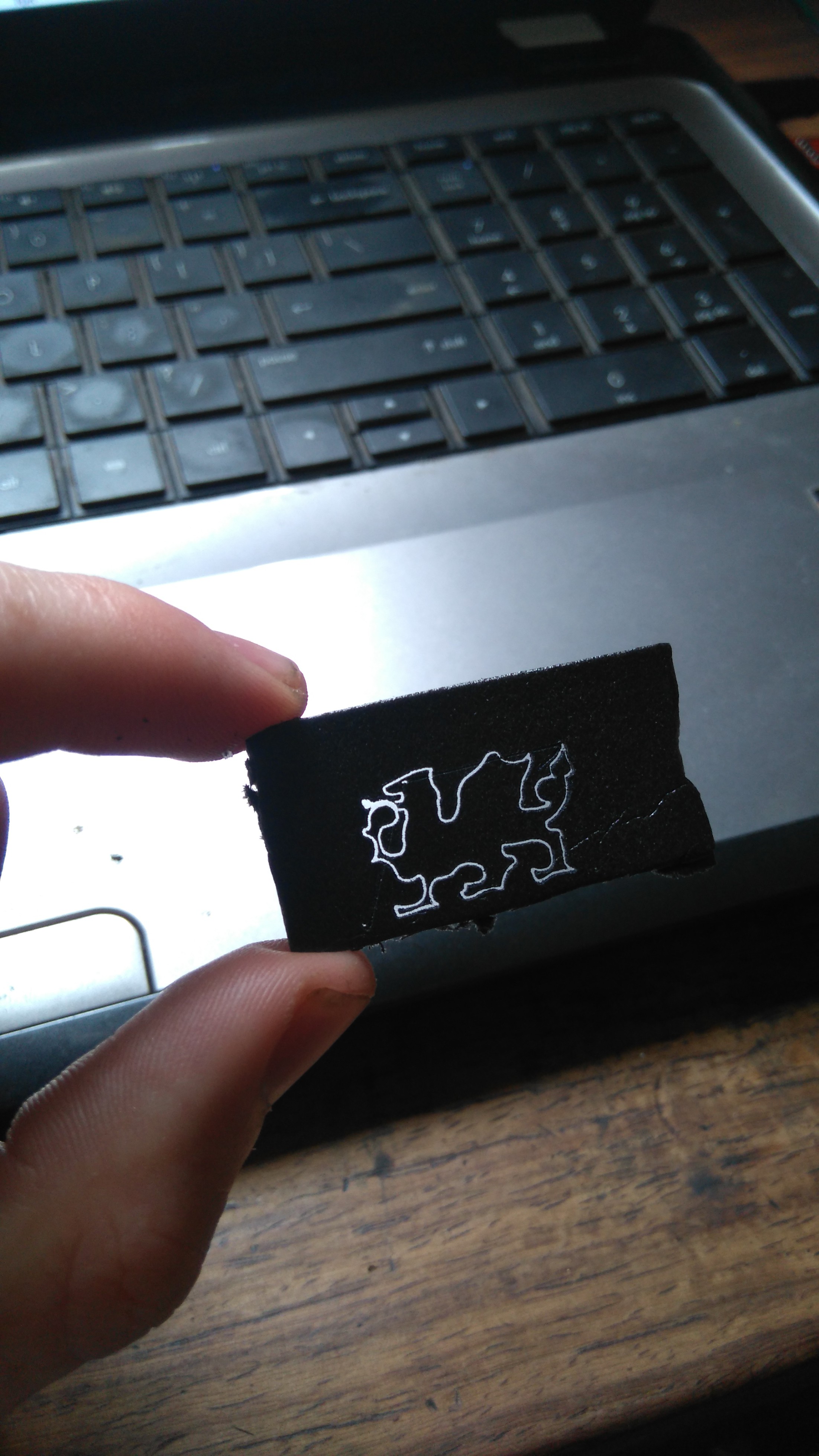
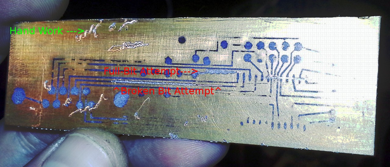
Here's the PCB (it was an early experiment with toner-transferring, several several several years ago):
![]()
The cut-squiggles are the results of trying these experiments by hand... Hard to do, the bit spins, and tries to walk. So with the test-jig I did several straight-lines, the best one's right in the middle. There's another experiment, kinda hard to see in the image, but above and to the right... That's the first test, with a fresh bit. The fluted part of the bit is quite long (half an inch?) and even with the test-jig the end of the bit managed to "walk" in a sinusoidal pattern that varied whether it was moving left or right. Possibly, with higher vertical precision and smaller passes it might work... But I managed to break the bit before another attempt.
So, the straight-line was done with a broken bit, only about 1mm of flutes remaining. I didn't have high-hopes for this working at all. With my hand-attempts, the broken bits seemed to have no cutting-power, they just marred the surface, and I couldn't even get them to plunge 1mm. But, three passes with the test-jig, and I broke through the copper and managed a pretty clean cut, as well. This is actually quite promising.
I think the width of the cut is larger than the bit, however. There could be several reasons. Of course, a broken-bit isn't really meant for cutting, so there's probably some weird forces at play. They might be causing some play in the rotary-tool and/or its mount. Regardless, I might not be able to do TQFPs with this setup, but obviously larger-pitch surface-mount would be doable. Besides, my understanding is that TQFP is difficult without a solder-mask... (That won't prevent me from trying!)
So, actually, this broken-bit multi-pass technique might be just-right. I did some searching for routing-bits and the smallest I found was 1/32nd (for $20!) which ain't too small when thinking about PCBs. And, hey, I saved all my broken bits :)
I'm not sure about the new design, using a rubber-belt... There's the heat issue, and there's the difficulty in actually replacing the bit. It's doable, but definitely not quick-change. And, it only works with bits that have the plastic sleeve. And a few other factors. OTOH, as nice as the other motor's knurled-shaft was for press-fits, it is *really* loud. Some thinking to do.
And, I mentioned yesterday that I had been filing-down the shaft on a right-angle drill-attachment. The purpose was to use it with my normal drills for its bigger chuck. Now I can use drill-bits with shafts up to 1/2in in diameter! Nice. But then it occurred to me that I could use it as a lathe...
![]()
In the chuck, in the image, is the 1/2in "pipe" I originally tried to use for mounting my bearings. I used a hack-saw while it was spinning, to cut straight-through (hey, no wonky-hack-saw angles!).
The shaft (sticking "up" from it, in the picture) took *hours* to file-down to fit in my drill chuck. Fun!
-
Brain-dump lest I forget...
11/13/2015 at 10:50 • 0 commentsKinda burnt-out, been working toward some sort of functional PCB-CNC/rotary-tool system, all day.
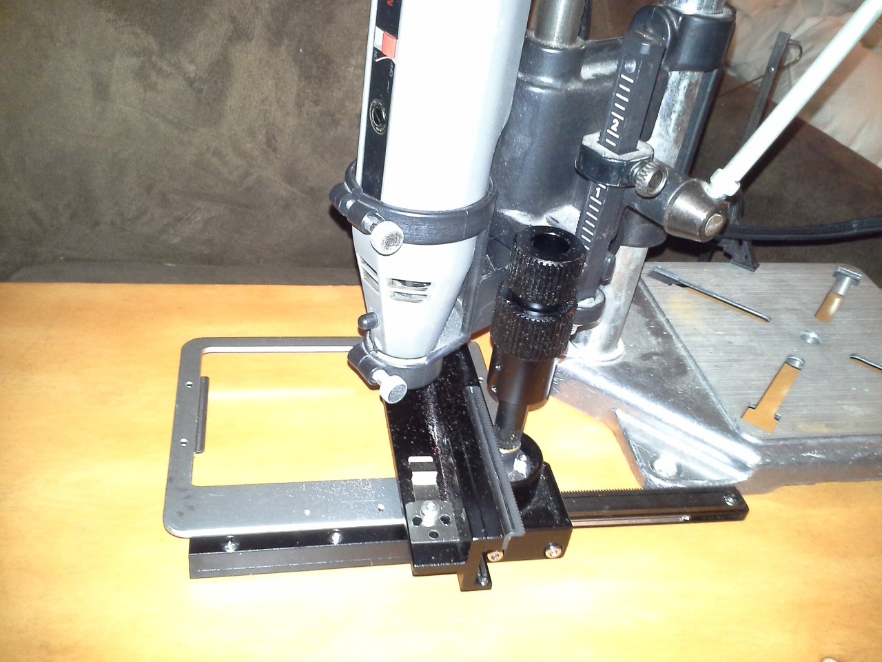
Decided to use the groovy microscope-slide mechanism my Pops found for me, but not exactly sure *why*, as it's been difficult to come up with a driving-solution. The thing is, the way its *designed* to be mounted results in the knobs *moving* *with* the motion of the slide. So I spent some time trying to figure out how to use stationarily-mounted motors and still allow it to move as-designed. End-Result.... Mount the dang thing differently. I did come up with a couple solutions for the mobile "knobs", one not unlike CoreXY. The first method requires *FOUR* motors for the two axes. The second method requires two motors, but one is dependent on the travel of the other, AND, this method requires three pulleys that are *exactly* the right diameters. If they're off just a little, the "pulling" motion of the motor will only work in one direction, there'd be a lot of slop, the belt would be loose in one direction. Oh, I think there was another 2-motor solution that requires "idler pulleys" that follow the motion of the knobs, but these are *really difficult* to attach, due to the geometry of the axes. The end-solution is to mount it in a way that it wasn't designed to be mounted, but it keeps the "knobs" stationary. Actually, this "mount" is the same sort of mount necessary for the idler-pulleys, but the idler-pulley method was difficult because it relies on the "mount" being *entirely* free-floating, whereas the stationary-knob "mount" (which, again, is the same) gets added-support from being stationary...
Anyways, Lucked-Out that I just happened to have a bunch of long bolts (with nuts already on 'em!) that have the right threading to replace some bolts already on the system... So they extend outward and I can attach them to a surface. Awesome.
Then the next difficulty is that the original mounting-method now becomes a moving axis, that axis happens to be the one that will support the Z-axis (the rotary-tool, in this case). And, again (previous log) there's the issue that the "slide" travels *under* this axis. Alright, PCBs are thin and can do this. Regardless, the actual cutting-bit needs to be offset by quite a bit from the mounting-point, which means I'll probably need to add another "glider" to support it.
So, let's just pretend that's all solved... what's next...?
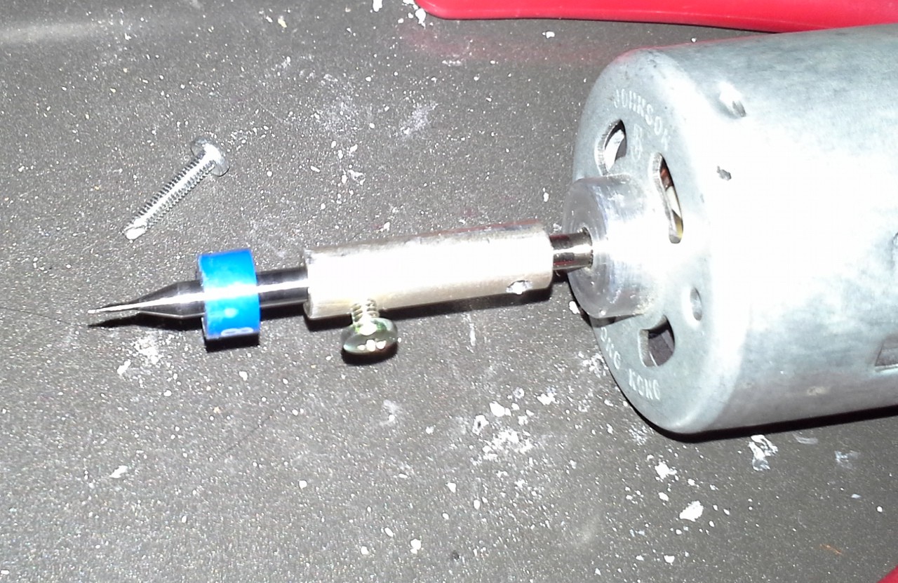
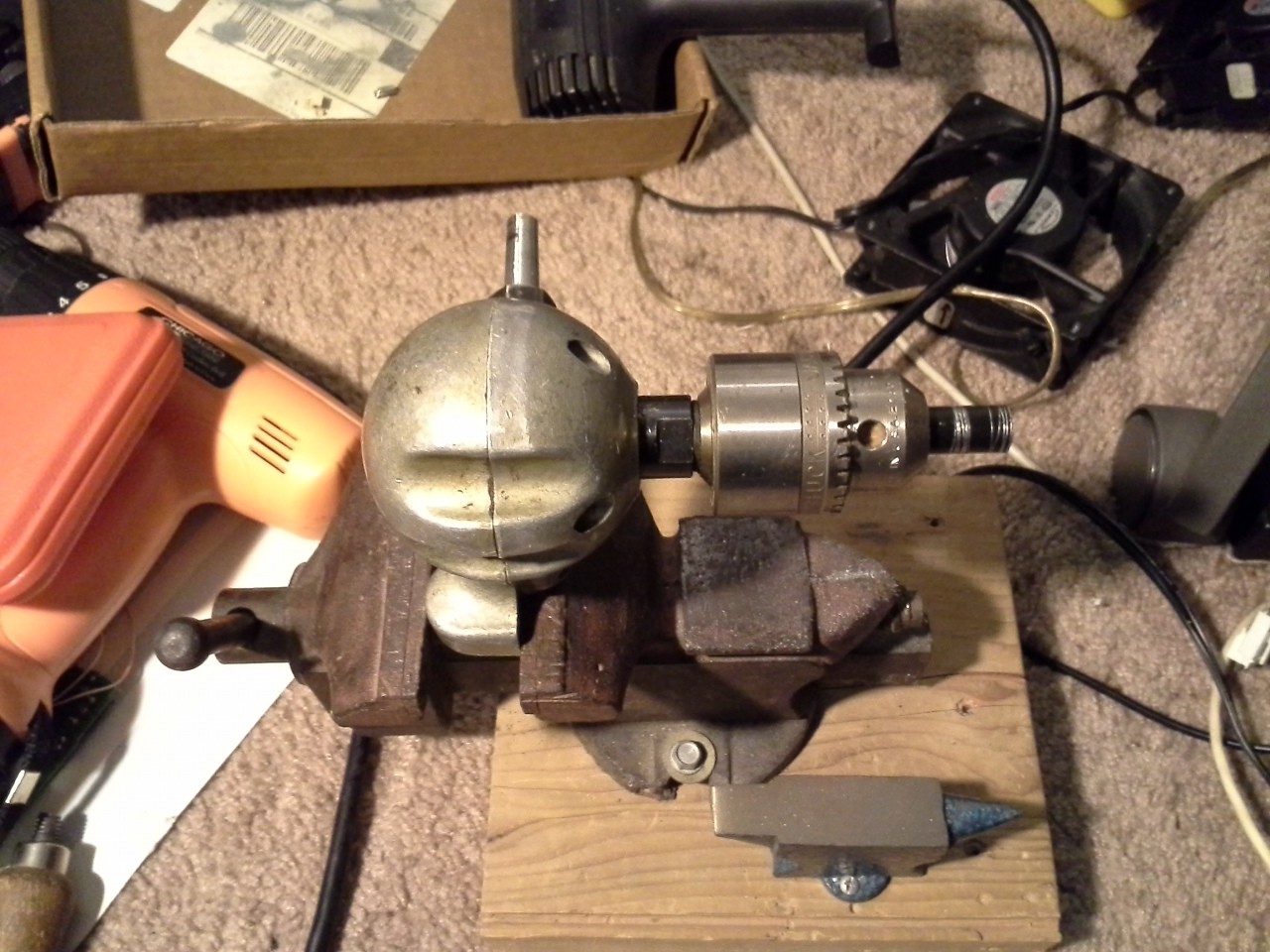
I need a friggin' rotary-tool. @Stefan Lochbrunner's project suggests using a "chuck" designed to attach to a regular-ol' DC motor. And, being broke, I decided it'd be easy to make my own rotary-tool chuck (since rotary-tool-bits always use 1/8in shafts)...Oy.
The Good: This'll leave my rotary-tool available for other purposes. Excellent. This is also quite a bit lighter, which is a good thing. It's also *smaller*, which makes mounting easier.
The Bad: Unless you have *exactly* the right-sized drill-bits, this is darn-near impossible. The end-result is about 1/8th inch "wobble" at the end of the bit. Whoa. There's no way to make a PCB with that. I've thought of a few things, but the end-result was a remake, then a total redesign.
Too bad, 'cause the whole process went amazingly smoothly until the wobble-thing at the very end. First, I needed to find a "dowel" of some sort, so I eventually came across a couple really-long threaded aluminum standoffs, leaving plenty of room to grip both shafts. The threads had to be drilled-out for the shafts, which is great, 'cause it was basically pre-drilled. Then I grabbed my tapping-tool to add set-screws but realized the smallest tap was too large, not only in diameter, but it would only have about 1-2 threads in the shaft-coupler. I had this crazy idea to cut sharp slots into regular ol' bolts (with much smaller threading) to *make* taps... (Hey, we're working with Aluminum, here, who knows...). And, lo-and-behold, I actually found the perfect bolts with a really tight threading *AND* apparently designed to be self-tapping (!?). I've certainly seen self-tapping wood screws, self-tapping sheet-metal screws, but I don't know that I'd ever noticed a self-tapping *bolt*. Wild. Cool. They're now *in* my tap/die set. I had no idea what size bit to use, but tried one, and it worked great. Oh, before that I predrilled the setscrew holes with the only drill-bits I have (besides 1/8th-inch) that will mount in my rotary-tool, so I could make use of its drill-press stand. Excellent. Those bits are *TINY*... smaller than most needles. Managed to drill both holes straight through, so decided two set-screws might not be a bad idea. Redrilled with my regular-'ol hand-drill with a size better-suited for "tapping" and despite the tiny holes that were barely big enough to have an effect on the larger bit, the redrilling and tapping worked perfectly.
I mean, seriously, the whole thing went so smoothly... Then I started to assemble it with the motor and realized that it was *just slightly* larger in diameter than the bits, and it happened to have "knurls" (?) on it... so why not press-fit the blasted thing? Oh yeah.
Oh and a few other bits and pieces here and there that just seemed to flow together so dang well, it was shocking.
Then... The wobble. Seriously, I'd say it's nearly 1/8in at the end of the bit. I tried bending, and various other things... I just can't get it right. I think what happened was I drilled once from one end, and I used one of the set-screws to keep the thing from spinning in the vice (didn't want to clamp it so hard as to warp the thing!). Then I switched the set-screw to the other side and drilled from the opposite side. I think, maybe, the drills didn't align perfectly. I don't think anything could be done about that, as far as bending goes.
Fought it for a bit. Gave up. Finally regained some motivation. Tried again from the beginning. This time *one drill* straight down the center. But, this time, decided to use a different motor, with a smaller shaft. Not sure why, exactly, but I think it's higher-quality and certainly much quieter (though probably slower). And I have several... And I haven't quite figured out how to remove the press-fit shaft-coupler from the other motor...
So, drill out the smaller diameter first... all the way through, then drill the other end (with the nearly-identical-sized predrill) for the 1/8in rotary-tool-bit shaft... Simple. But, I don't have a drill-bit that matches this motor's shaft. I have one that's slightly smaller... So, right, brilliant, 'cause I didn't get the point of wobble before... I drilled it out, then widened it as best I could... and it was just wide enough for the motor at the end I was working, and apparently *too wide* for the 1/8in bits at the other end. Whoa. Alright, I give up, wobble's not gonna be avoidable with my tools.
How do they make rotary-tools so precise that that *tiny* bit could drill a perfectly *tiny* hole?! I bet it has something to do with a long body and bearings at each end. Well, I don't have a long body to work with, here... and I can't get alignment in my shaft-couplers to the tolerances most anyone (and certainly a tool-manufacturer) could do with the right tools...
How can we avoid this...? Well, I don't have any U-Joints that'd handle these speeds and could easily be attached-to at both sides... So... here's where we're at right now...
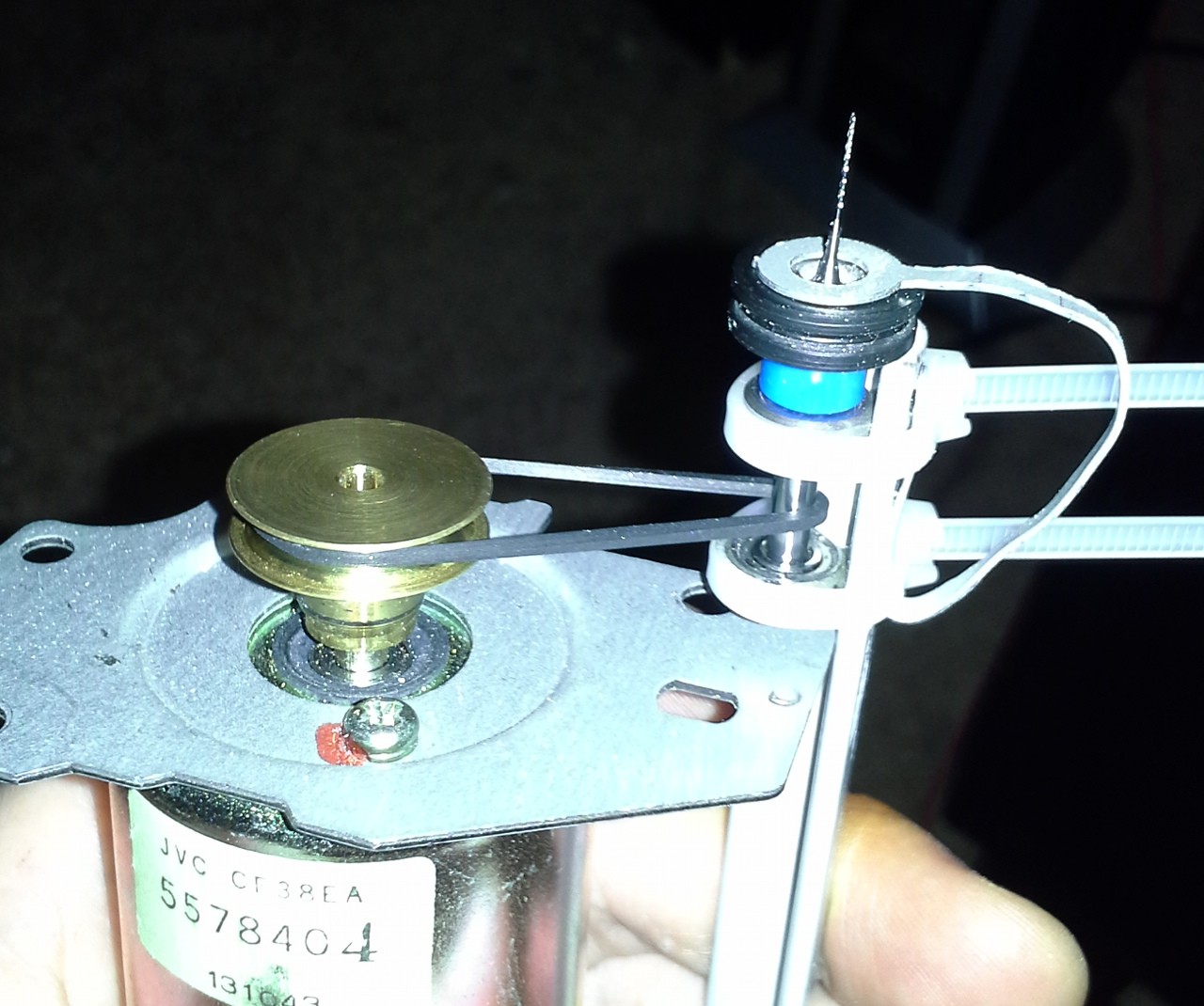
I have ball-bearings that are *almost* perfect for a 1/8in shaft. They're a *tiny* bit loose, but not much. So, two bearings where the bit normally mounts in the chuck, but that would fall-out. So, a third (easily dis/reattached) bearing under the bit's plastic size-indicator. This, also, serves the benefit of preventing up/down slop, which would have to be considered in the directly-coupled design, since apparently many motors have axial slop (interesting). Also, it serves to prevent the bit from torquing while being dragged along the PCB.
So, in all, I think this'll be a good route, but it means I've got to figure out how to support these three bearings. First-Go, I have a hollow-rod (a pipe, really) that's almost exactly the right size, but needs to be drilled-out slightly. Fine. I have a drill-bit that is almost exactly the right size... Drill it out as best I can... Turns out, it's easier to drill more precisely *in reverse* where it won't *grab* the material. Excellent. Drilled out enough for the two bearings surrounding the plastic size-indicator, then planned to cut the "pipe" to drill-out the same just long-enough for the third bearing at the end of the shaft. Looked *everywhere* in my home for a matching screw to mate with the end of the pipe (preferably an end-cap sorta thing, which I'dve drilled out if necessary to allow the bit to protrude as well as be changed easily), but couldn't find any. Fine... I'll figure something out... Not sure when I decided to drill it out just a little bit more, but I did... and lo-and-behold, apparently the inner diameter of the pipe is actually *wider* than the bearings, once you get past the threaded-portion (of the pipe). Now... well, we have wobbling bearings.
So, where we at now...?
Did I mention that my plan is to spin the bit with a rubber belt? Yeah, that's of some questionability...
So, I think I'm going to drill out a block of wood to support the bearings. (it *just* occurred to me, maybe I could set-screw the bearings? Hmm, maybe even in the pipe...?)
That's basically where I'm at... THIS part IS relevant to [my] CD/DVD mechanism project... Lasers are cool and all, but I think it'd be more useful if I attach a rotary-tool. I chose to work with the other mechanism mostly 'cause it's larger... But as @John Pfeiffer pointed out, 40mm x 40mm (DVD-mechanism) is actually a pretty decent size for a PCB. It's much bigger than #The Square Inch Project! Heck, the last several boards I ordered were 50x50 and had lots of free space. So, I'm kinda tempted to revisit this. The last experiments with the "Secret Project" were finally repeatable with microstepping (which seems to help reduce missed-steps due to loading). (I think the lack of repeatability was due to using the wrong supply voltage). And, if I recall correctly, single-stepping gives 1055 steps end-to-end, which didn't seem like much at the time, but is actually something like 0.04mm precision, that's pretty dang good for a PCB, if I can fix this wobble-problem!
Oh, and I finally figured out how to squeeze a few more fractions-of-an-inch out of my cheapo cordless drills... I've had an old (wooden-handled) right-angle drill-attachment in storage for longer than I can remember. It has a 1/2in chuck! So I took a Hex-standoff and chucked it up between my drill's and this thing's chucks, and spun the drill so the right-angle-thing's shaft spun... Its shaft acting as though it was chucked up in a lathe, I filed that shaft down until it fit in my drills, and now a chuck-size-adapter.
Shoulda done this years ago. Not only does it make for a larger chuck, but it also mounts easily in a vice to use as a lathe of sorts. Much more stable than just a bare drill. Excellent.
-
back-"burner"ed for a bit, plus some inspiration
11/12/2015 at 05:25 • 0 comments@Stefan Lochbrunner has thrown up some of his #Computer Numerical Considerations, definitely worth a look for some inspiration. Which is timely, because, if you haven't noticed, this project (at least on my front) has been sorta thrown on the back-"burner." He uses a CD/DVD part in his build, but it's not the part you'd expect. Check it out!
In other news, my Pops found this groovy thing in the recycle-bin at work:
![]()
It's made by Nikon, but doesn't have any part-numbers, but I did manage to find it via image-search, and it turns out to be a carriage for microscope slides, and has quite a bit of travel in X-Y fashion, around 5 inches in one direction, and three in the other.
It's meant to be hand-driven, but I dug through my old belts and pulleys from old printers and such and found mates for both coaxial "knurled"(?) knobs. Oddly, the two knobs have different "tooth" spacing. One is apparently common-enough that I have *several* belts of different sizes to mate with it. But the other only matches one belt in my collection, which happens to be a good 8inches in diameter. A bit excessive, but I guess it doesn't really matter.
I spent some time contemplating its use in a PCB mill... I think it could be done, but it wasn't exactly designed for too much loading. Also, the original microscope slide actually travels *under* one axis, which would be fine for PCBs, but I contemplated other mounting-methods for e.g. routing 3D things...
![]()
That foam-core stuff is handier than I expected for quick-experimenting like this! And here I thought it was just packing-material...
So, if I mount the rotary-tool at the '>' on the top piece of foam-core, then I can route within the four dots on the other, without the piece going under any axis, and with the loading being somewhat centered on the lower axis (which will be supporting the piece).
Or, yahknow, weeks later I might discover that I could flip the whole thing upside-down and it doesn't go "under" any axis at all... duh. Anyways, still need to consider adding a separate support-glider on each axis, still in the works.
In other other news, thought about using an old flatbed scanner for one axis, an inkjet printer for the other... Finally dug that scanner/printer combo I found next to the dumpster out of storage... Interestingly, it only has one glider, in the middle, so not really well suited for carrying an inkjet mechanism and rotary-tool on top. On a whim decided to press the "copy" button, and sure-enough not only did it scan fine, it also *prints* fine... in color. Dunno why it was by the dumpster, but now I have my own copy-machine!
Cool observation: Apparently they started using LEDs instead of CCFLs, so you can actually see it switching colors as it scans (or scan in green, when doing B/W).
So... where's this leave us...?
Oh, the old inkjet I took apart many months ago... turns out that thing doesn't actually have a rod-glider, the ink-carriage rides on a bent piece of metal... So, it really wouldn't take much torque to rip out the plastic that's gliding on it... And any vertical pressure (e.g. from a rotary-tool) would push it right off the glider. Another consideration.
I have two identical printers which I thought to use as one wide axis, could drive the two motors with the same motion-profile... but I'm having a hard time breaking up with these printers, they were an investment for photo-printing a while back, but they are going through the ink trying to unclog those heads...
And a yet another printer that happens to be wide-format... which, again, printed right off the bat, despite having been in storage since it was given to me as non-functional 5+ years ago. 11x17 is sure nice for things like schematics... (Nevermind I have a stack of 11x17 paper).
Soooo... now to decide whether to take things apart which are functional and useful...
If I did the two normal printers as one axis, and the wide-format mounted atop as the other, that'd be >8.5x11 work-area, which would be a decent size for actually doing things... PCBs, wood-work, and more.
And, of course, none of this is based on CD/DVD mechanisms...
-
LaserDisk HaD Logo, coordinate-changes, ++
10/08/2015 at 11:33 • 0 comments![]()
![]()
Wow, I had to convert between 4 or 5 coordinate systems to finally get the images proper... There's the cartesian coordinates of the image itself, that have to be scaled to fit within the "window" on the diskette... There's the polar coordinates, in real-life (mm, radians)... There's conversion from mm to "steps" of the steppers... Then since the vertical motor homes at the top, rather than the bottom, there's a strange sort of "polar coordinates" used for actually moving the steppers... So rather'n a radius and an angle, we have a distance from top, and an angle. Confusing.
Anyways, broken down into steps it's not *that* complicated, but there was *plenty* of room for error, and amazingly didn't run into any math/conceptual/code-errors in those conversions. OTOH there was a stupid oversight at the very end during the drawing-routine, and there's some work to be done with making sure the image fits within the "window" that can physically move around, and the fact that the disk itself doesn't fill up the entire window... For now, simply make sure the image drawn has a blank border...
It definitely makes a huge difference converting to polar... A couple images done when I treated it as rectangular can't even be discerned... So there's that huge improvement.
Also, I think the vertical motion repeatability problem was largely due to a few factors: A) I was trying out running the 5V side of the H-Bridge at 3.6V (to match my microcontroller), which seemed to work fine for quite some time, but switching to 5V seemed to help the repeatability quite a bit. B) It was mounted somewhat vertically, and I think some of the missed steps might've had to do with the weight. C) There was the "slop" in the rotational-"engagement" mechanism... I put a couple rare-earth magnets on the rotational-mechanism to hold the disk tight, and it seems to have helped.
-
LaserDisk (not Disc), microstepping, laser focussing
10/05/2015 at 10:33 • 0 commentsFinally got the code running to draw some images...
Ran into a couple hurdles. The laser was positioned almost perfectly, then something unexpected happened... The disk warped due to the heat. And, in the process, the laser was no longer in focus, believe it or not, even though the disk is sandwitched in its case and could only warp a tiny bit... it wouldn't burn.
So I came up with an idea... Why not just move the focus of the laser back and forth? The end-result is simply that it sits at each point for a few seconds while adjusting focus between its maxima. Was pretty easy to do, the same H-Bridge chips I'm using for the steppers seem to work fine for the lens's "voice-coil." PWM, (one resistor), and done.
![]()
The images don't quite look right, however... The columns seem staggered, as though the vertical motor isn't positioning to the same point each time. I'm not sure what the reasoning for this is... maybe it has to do with my microstepping technique. There's certainly plenty of "slop" in the *rotational* axis, but that shouldn't affect the vertical (unless the rotational axis reverses direction, take a look at the "engagement" mechanism on a floppy next time you see one, they're not exactly precise).
I tried a couple different techniques. The first was obviously too hopeful, drawing in a zig-zag raster-fashion... One column down, the next up, etc. Then I tried "homing" between each column... The vertical motor/carriage reacts differently depending on which extreme is "hit". At the lower extreme, the sled's attachment to the worm-gear slips, apparently intentionally. Fine, but there's really no way for the system to know when it will reengage; it may happen in a half a turn, or a quarter-turn, etc. At the upper extreme, however, the motor itself is actually stalled, and misses steps. This seemed to me like a great place to "home", since the motor would always be at the same position (right?). Well, that may be contributing to these staggered columns, as I had run some other experiments that suggest it doesn't actually arrive at the same position each time, even after homing. (Maybe if I did *not* use microstepping during homing... hmmm...)
And, as far as the rotational motor, I tried to measure the "engagement slip" to allow for back-and-forth motion, but it was flakey. And, later, I noticed that the disk actually shifts vertically depending on which direction it's rotating (again, take a look at the floppy engagement thing, it makes sense; it's slanted). Woot!
And then there's the rubber-wheel I'm using, which might lend to some more imprecision, as well as requiring a certain amount of force on the motor's shaft... And... That amount of force is *right at* the limit for how much the stepper can drive without missing steps. Weird.
Anyways, here's the results:
This was a much-too-hopeful first-drawing attempt of the cat... If you look close, you might see one, but if you look at the actual image, you might be surprised. (You can also see the warping of the disk).
![]()
![]()
This was a test to see how much of the badness of the last image was due to image-skew... I treated it as though the vertical and horizontal were perpendicular rather'n radial... this would be a rectangle...
![]()
And, there (and here), you can see the weird jaggedness in vertical offsets...
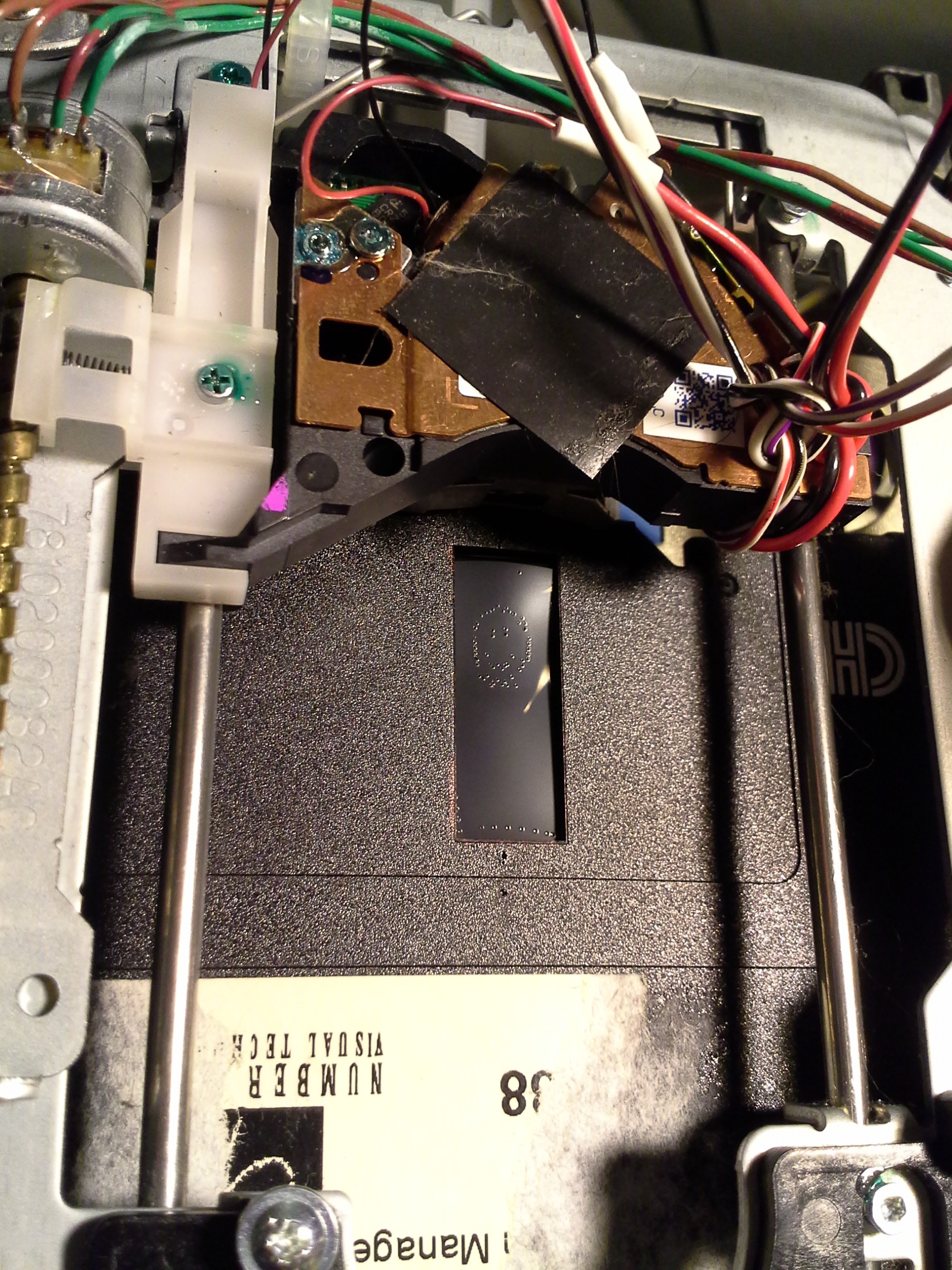
Below is supposed to be a smiley-face, not a Pacman ghost!
![]()
-
"Secret Side-Project" Revealed
09/28/2015 at 10:37 • 6 commentsUpdate 9-29-15-2.0: Adding photo of "tapped" mouse at the bottom.
Update 9-29-15: Adding schematic at the bottom.
Wanted to get the whole system running and make a video of the whole shebang for the "reveal", but decided it's too cool as-is :)
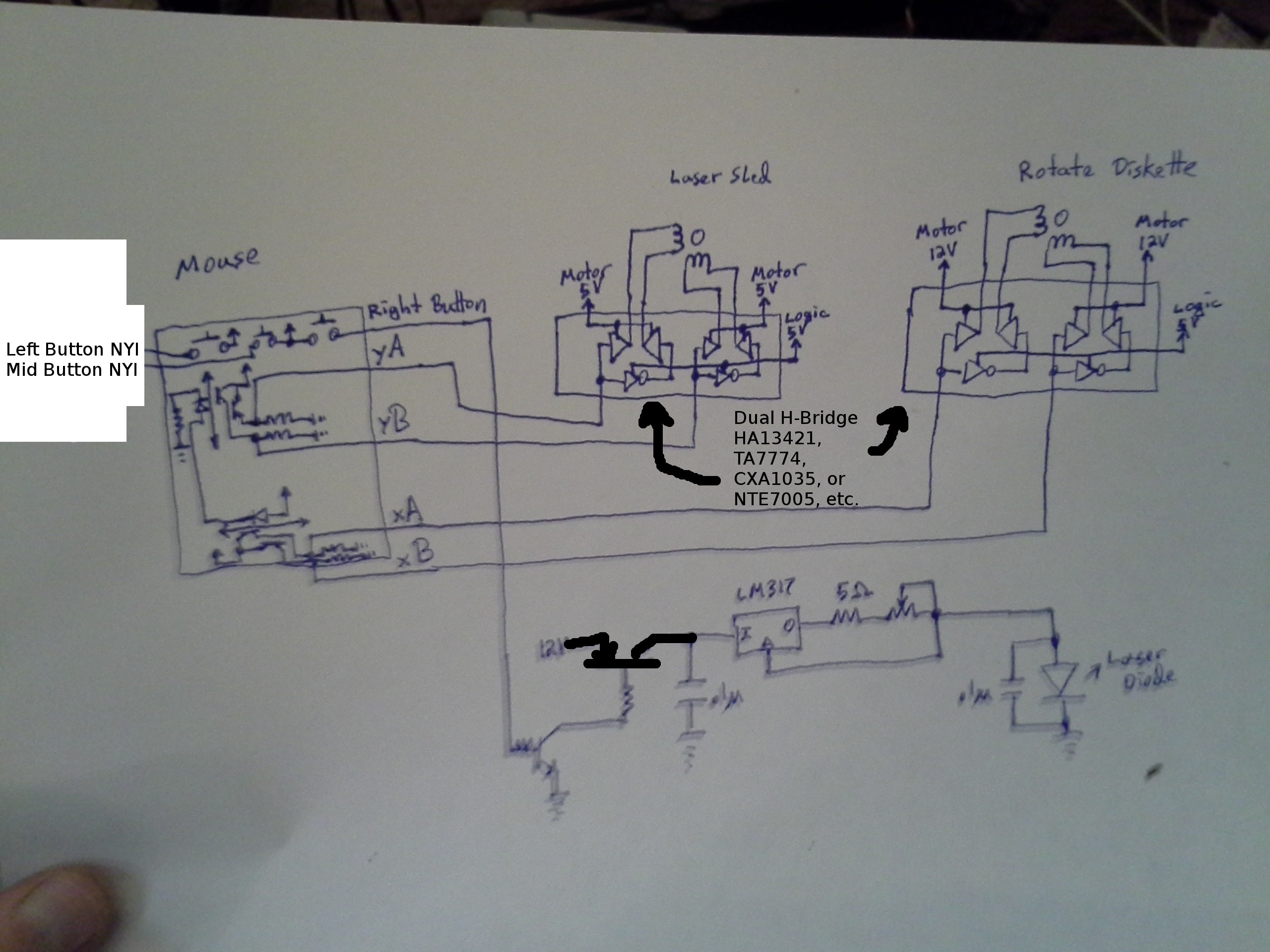
So, there's an old ball-mouse, its phototransistors and buttons have been "tapped" to feed directly into the system's circuitry. The circuitry consists of nothing more than two Dual H-Bridge chips (designed for bipolar motors, from old floppy drives), a couple transistors to switch on and off the laser-diode's circuitry, and a few LEDs, capacitors, and resistors. No software! No microcontroller!
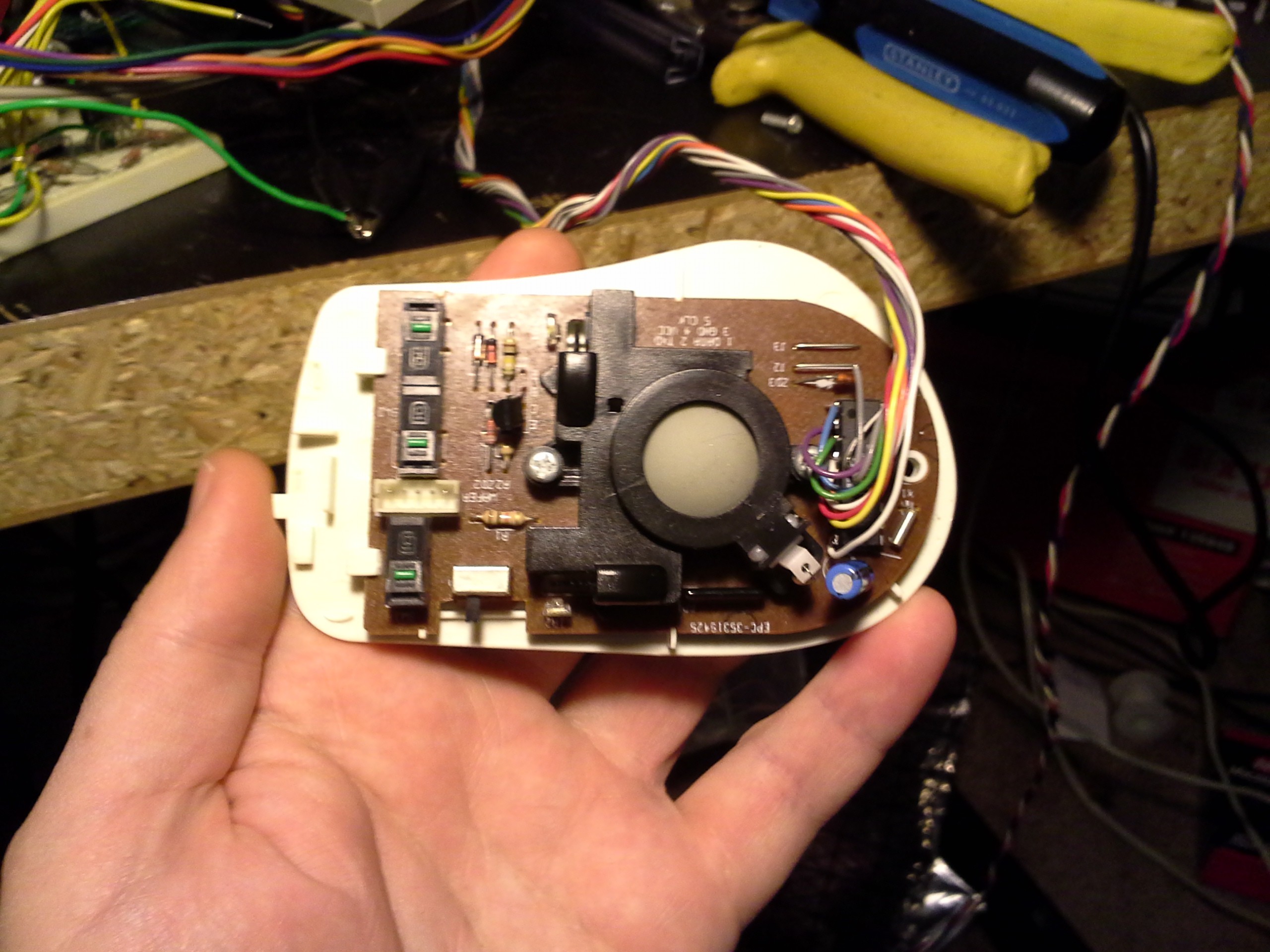
As far as mouse-hacking: I didn't even bother interfacing-with (nor even removing) the original PS-2 microcontroller from the mouse; just tapped off the signal inputs right at the microcontroller. This could be quite the handy tool for later experiments and early-phase projects, as well.
Later, I do intend on controlling this via computer, to literally "burn" images onto floppies. I've looked into backlighting, a little, possibly strobed to create a zoetrope. And a multitude of other crazy ideas, including audio-storage ala CD, but with visible "pits." Who knows...
Here's the schematic:
![]()
Here's the "tapped" mouse... I followed the traces to the built-in microcontroller, it could be physically removed, as it's not being used, but it was an easy solder-point.
![]()
CD/DVD mechanisms and cartesian thinggie[s?]
DVD-laser-etcher, dremmel-router, possibly a 3D printer? Who knows!