Eric Hertz
-
Secret Art [side] Project
09/23/2015 at 10:36 • 2 commentsWas experimenting with materials to burn with the laser... and came across one that takes it *real* well. So, I'm assembling an appropriate system to handle this material...
For now, I'mma keep it secret. Most of the hardware's in-place, just need a couple bolts to hold it together, and maybe a rubberband or something a tad more sophisticated, but I kinda want to see it working, so might stick with a rubberband and get on the software sooner rather'n later.
A major nicety. (@frankstripod would dig this one) It works with the original laser-focusing head, in the original sled/rail-system. No additional optics. The "material" seems to be *exactly* at the right position when the focusing head is fully-extended. Just figure out which coil(s) extend the head by applying 5V through a resistor around 150ohms.
This won't be a cartesian system, it'll use polar-coordinates. I kinda dig it.
What else am I willing to share at this point...? I've got *a lot* of this material, and it comes (came) in two common sizes (though I'll need to assemble another mechanism for the larger size).
Oh, the polar-coordinates... well, I'd like for the system to handle vector images, but the mechanics don't really allow for reversing the rotation, so it might have to be pseudo-raster-style (spiral?), at least for now. Rotation-reversing seems doable with neodymium magnets, but the ones I've tested cause some drag. Also, what with the steppers and not having microstepping implemented yet, this will probably be pixellated, anyhow.
Which reminds me, I need to figure out how to drive the rotational motion... The original system, I think, is too fast for the laser to do its job. Besides, the circuit-board/motor, that came with the hardware I ended up using, is a bit difficult to interface. But now that I realized extending of the focusing-lens... well, I might be able to get away with some other hardware where the circuitry is easier/easy to interface... if it will burn at that speed.
I've a few ideas for this... one is graphics, even motion-graphics(!?). Another is e.g. audio-storage, possibly data. It's utterly ridiculous to use it for those purposes, but I still dig it.
Planning on a backlight, for sure, for viewing the images... Possibly strobed for motion-images (a zoetrope?). For audio/data read-back maybe a solar-cell (which is handy since it's so large compared to a photodiode, no need to move the read-back sensor! Thanks to this guy using a solar-cell position-sensor used in a ball-balancing system for the brilliant idea! #Balance Wheel).
So, to recap: Two 'systems' in great supply (free). Material in great supply (free). Potentially all the motor-driver circuitry is easy to interface and free with one of the 'systems'. Might even be controlled via a parallel-port. Possible motion-graphics... And utter ridiculosity and irony in one! Wee!
Oh, and the possibility for strobed "columns" wherein the images are spread and interwoven over the entire "wheel," only visible with strobing (or possibly another wheel spinning?)
Possibly even something like this:
-
ramblings on microstepping [bipolar] steppers
09/18/2015 at 08:21 • 0 commentsIn an earlier log I commented something along the lines of: "reducing missed-steps by microstepping unipolar stepper motors makes sense to me, but I can't quite wrap my head around why microstepping bipolars would result in reduction of missed-steps."
So I spent a few hours the other day thinking about the matter.
Now, this is purely hypothesis...
![]()
Obviously, I wouldn't have to hypothesize on the matter if I was some sort of stepper-expert. And, frankly, I didn't even look online to see if my idea of the poles of the rotor make sense. (Somewhere I recall a vague idea that steppers have one less "tooth" on the rotor than the number of electro-magnets' teeth.) This is an exercise in deductive-reasoning, and this is what I came up with.
Anyways, the idea is similar to two solenoids pulling against each other... an experiment I did a while back. Imagine two solenoids equally powered, and their... shaft(?) is shared. One's pulling left, the other right. They should be pulling with equal-force, right? And the shaft should be held somewhere in the middle, right? Nah... Whichever is closer "wins". (What if the shaft was magnetized?)
So, in the bipolar stepper case, say both windings are pulling equally, you'd expect the rotor to be halfway between steps, but realistically, it'll either stay at whichever step it's already at, or an external force may (easily) force it to snap between one or two stable-ish positions.
Another case, for instance, is when one set of windings is *opposing* the magnet on the rotor, while another is *attracting*... Say the motor's stable/stationary at that point, already... Then, as I see it, the attractive-force is pulling the rotor in opposite directions; not rotationally, but radially. That's a pretty stable holding-position. The opposing magnets, on the other hand, are pushing the rotor *inward* toward each other... again, not rotationally, but radially. Their forces cancel each other out. The shaft doesn't really want to rotate, it just feels a crushing sensation.
Again, there may be some features of steppers I haven't really taken into consideration. E.G. there may be 4 windings and 3 poles on the rotor. But the concept is out there to mull-over... that there may be somewhat "stable" positions wherein the most-stable position may be at one step, but since it's already at another step, it doesn't really want to move to that "most-stable" position.
So, throwing about some microstepping, we have a bit more ability to force the rotor to rotate between these positions. A bit more control over the process of moving from one position to the next.
Anyways, microstepping a bipolar stepper shouldn't be much more difficult than microstepping a unipolar. In fact, it seems to me, that driving a unipolar stepper with a bipolar signal (not the *same* signal as used by a bipolar motor, but a signal that does in fact switch between two different poles, thus bipolar) ...doing-so would probably increase the holding/positioning-power of unipolar steppers, as well. It'd require twice(?) as many H-Bridges, but doable. I guess, really, it depends on whether the unipolars have magnetized rotors, or if the rotor is merely ferrous. But, again, I read somewhere that unipolars can be made bipolar by tying their windings together, which seems to imply magnetic (rather'n "passive") rotors.
So here's how I'm seeing it:
In a unipolar configuration, even with some forms of microstepping, there's basically a pull-only mode... Each winding is essentially pulling the rotor around in sequence. Between steps, two windings pull at the same time, with varying power, so it pulls more toward one than the other. In the bipolar case, there's a pulling *and* a pushing involved. When not microstepping, two windings could be pulling, or one could be pulling while the other is pushing. Interesting to ponder, but a bit outside my headspace at the moment.
Anyways, it's certainly *easier* to consider a stepper motor a motor that steps between positions rather than thinking of it like a really-high-precision brushless DC motor, or even a multiphase AC motor, which they both basically are. No?
-
DC Motor Revisited + Another one [laser] bites the dust [beam-focussing]
09/15/2015 at 00:39 • 0 commentsMighta crammed too much into this one... Click that Read-More link!
Positioning a DC-motor-based CD-carriage, DVD-laser beam-diameter focusing, and a touch on microstepping... whew!
![]()
![]()
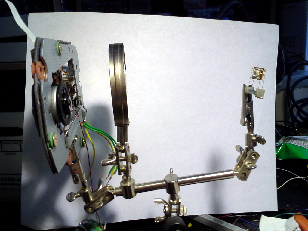
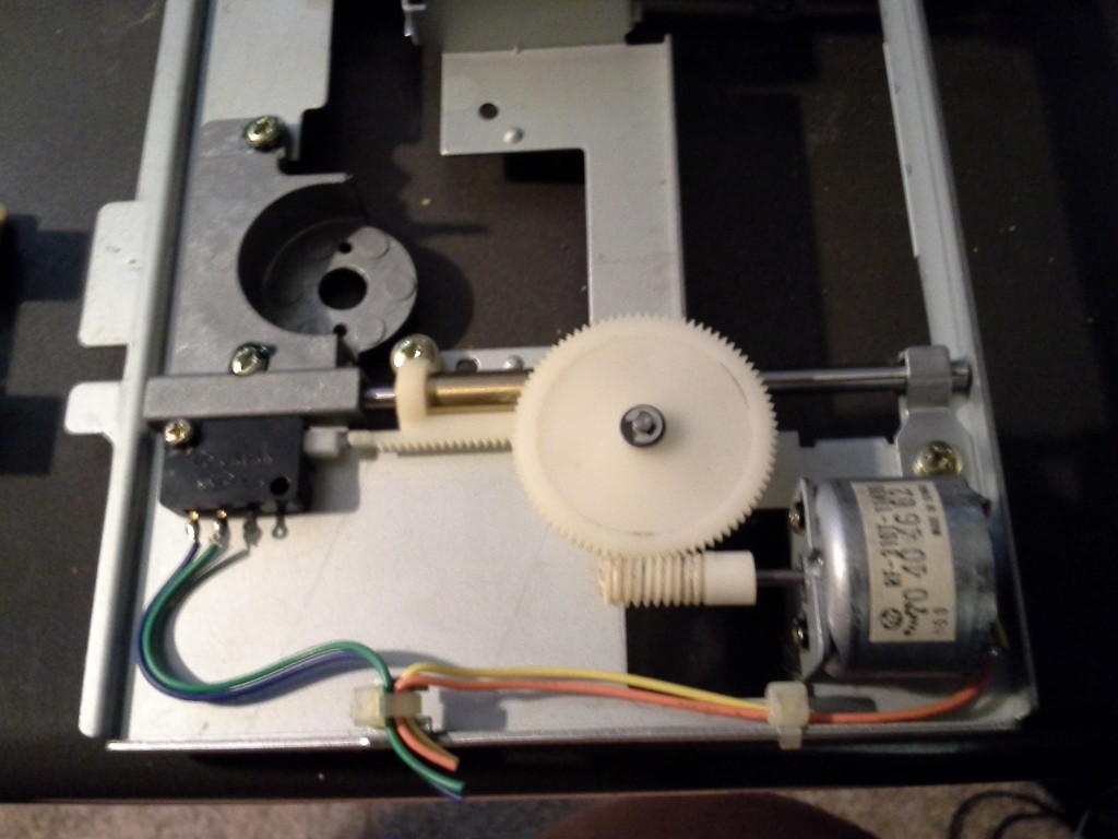
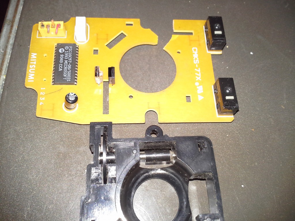
One of my drive-mechanisms is quite large and sturdy... If I recall correctly, it came from an old stereo-component CD player, and is built like a tank. I think it will make for a good axis, despite having a DC motor instead of a stepper.
![]()
And look at all that space between the shaft and worm-gear... Perfect for attaching an encoder.
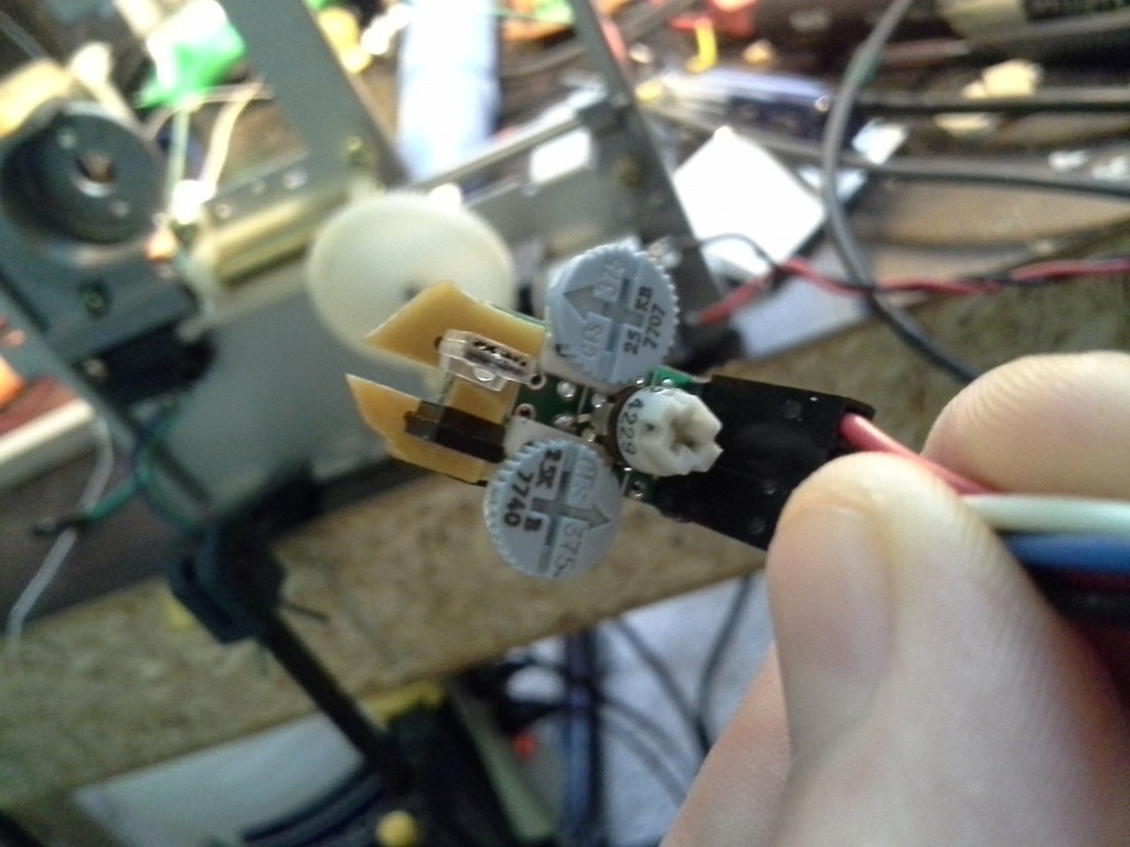
I've stripped an encoder wheel, opto-electronics, and frame from an old ball-mouse.
![]()
And, with a little work, was able to attach it to the carriage mechanism...
![]()
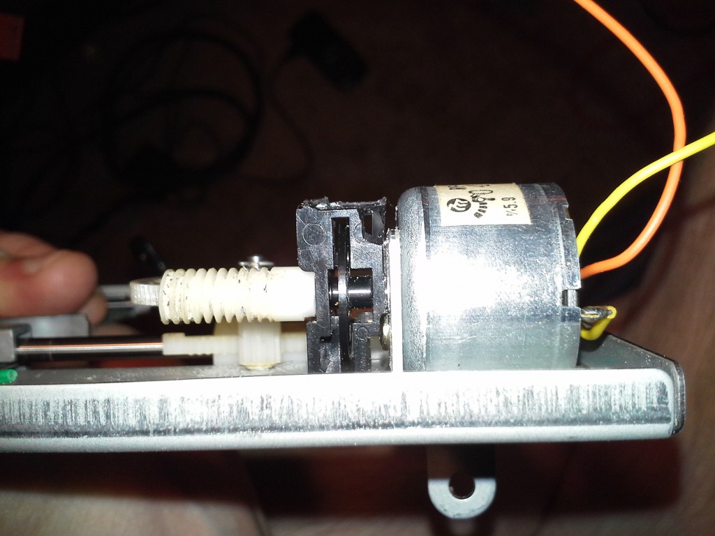
(Hey, if you've got to do a little bit of lathing to the worm-gear, consider the fact it's already attached to a lathe of sorts! 12V on that motor and a file!)
![]()
I used a portion of the original PCB for structural support, and soldered my own circuit to that...
![]()
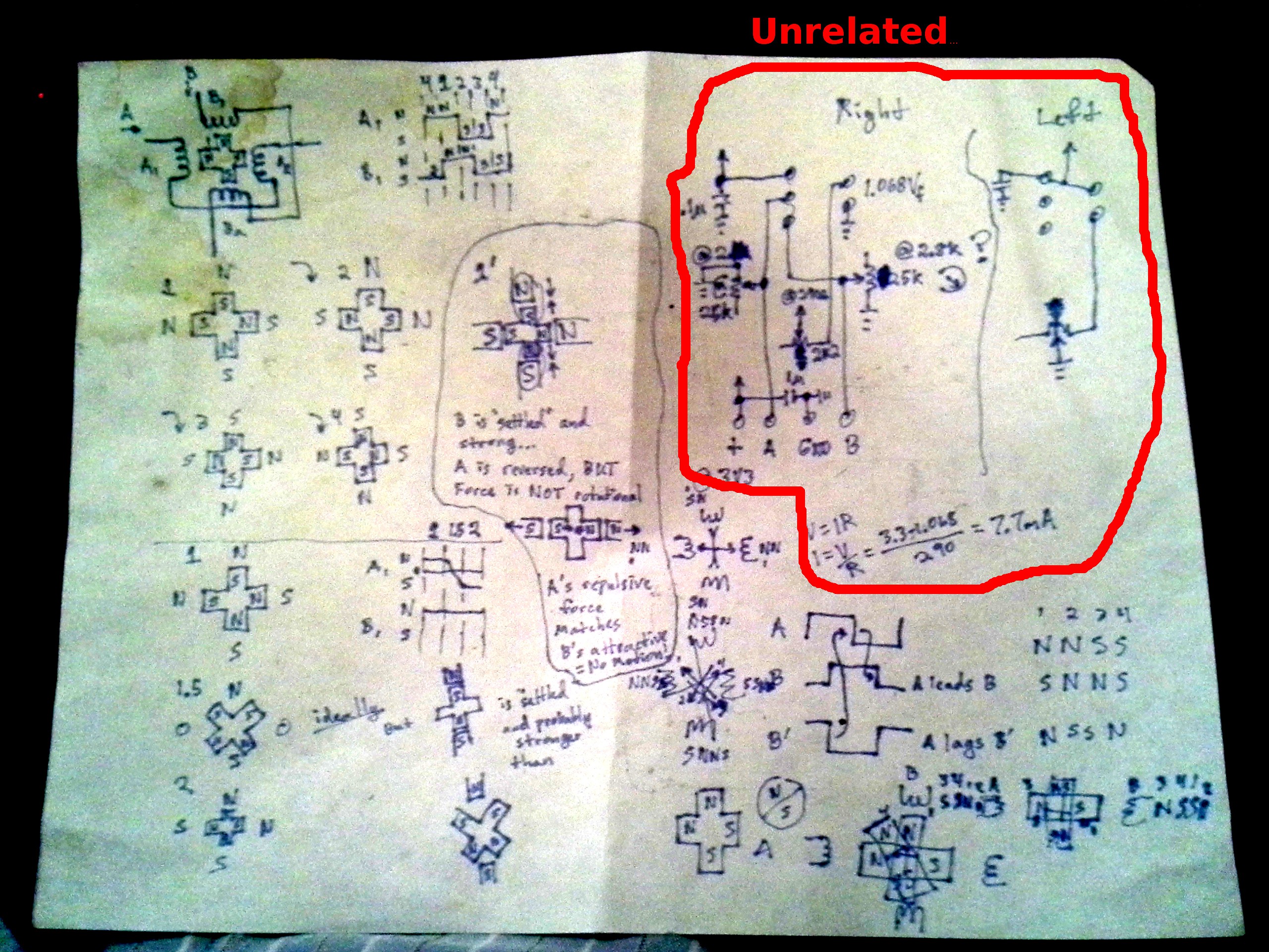
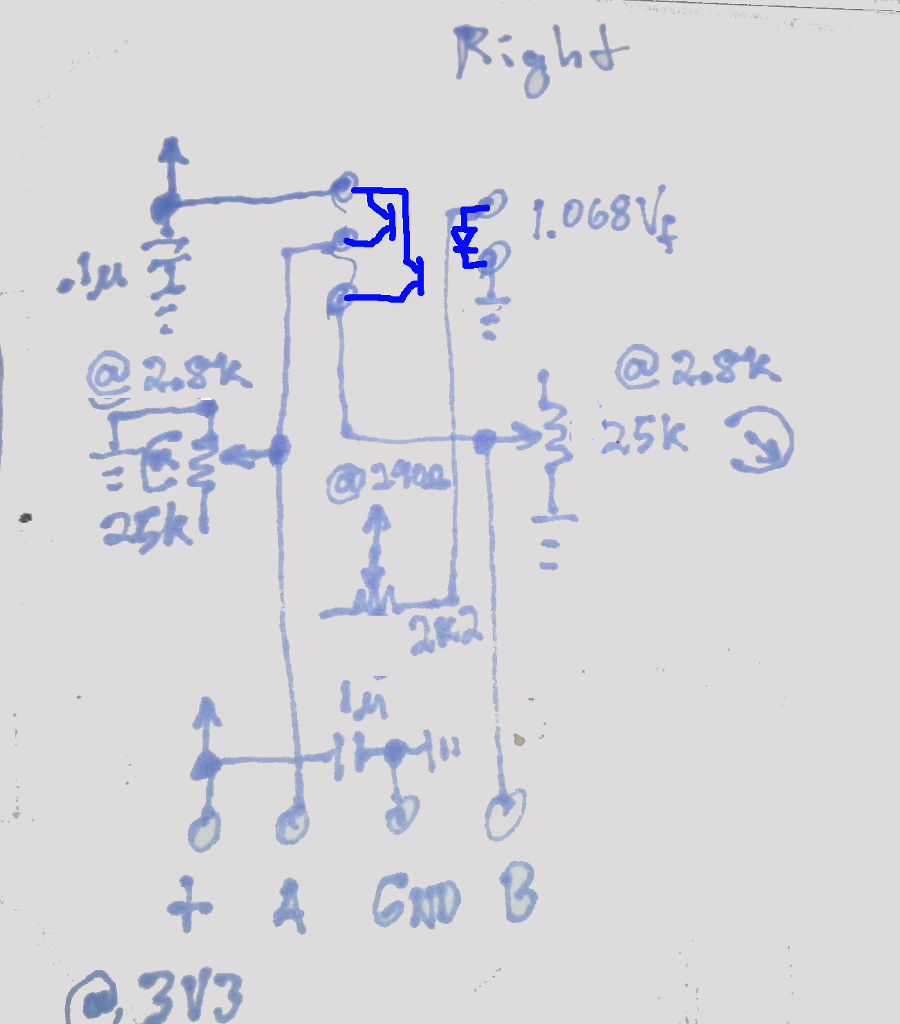
The outputs of the phototransistor are analog, so it needs a bit of calibration depending on the voltage, etc. The two 25k potentiometers are set to about 2.8k, and pull the phototransistors' outputs to ground. The middle potentiometer is set to about 210ohms giving roughly 7mA current through the photodiode.
![]()
This is for a 3.3V system, the original circuit in the mouse was tuned for 5V and had the two axes' LEDs in series. Also, even at 5V, the original circuit didn't work well with high-speed rotation, the signal swing diminished dramatically. These values were found by adjusting the pots while 'scoping, with the motor running at full-power.
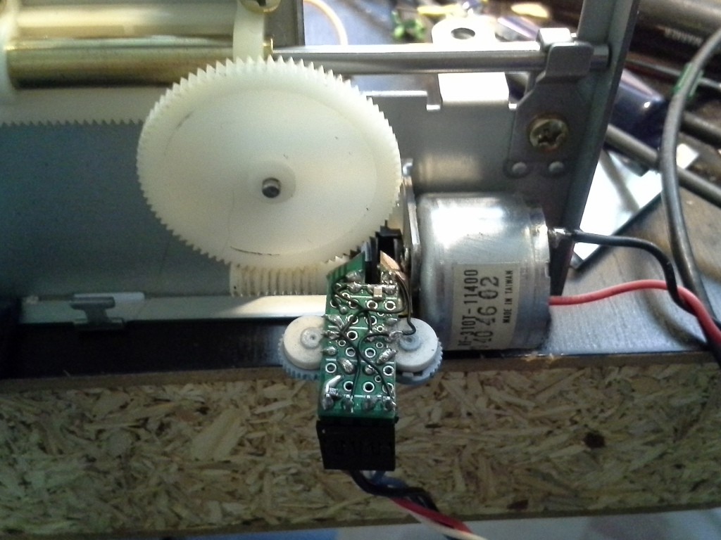
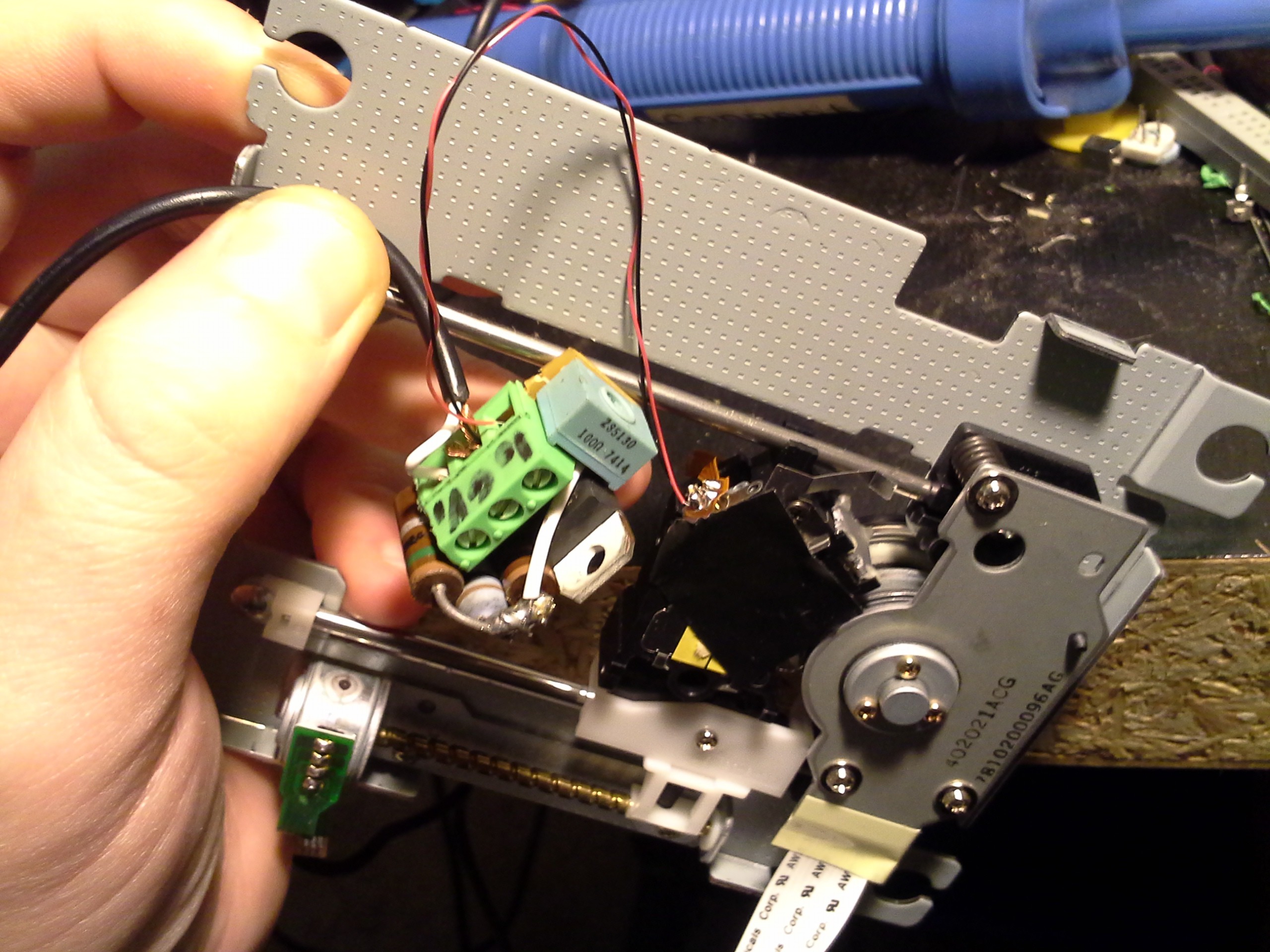
Here's the full setup...
![]()
It seems we can get pretty high accuracy out of this motor... Unlike the cheaper "hobby"/"toy" motors experimented with earlier, this has much "softer" poles. So, running it at a very slow speed, we see that there's very slight "snapping" action. And, geared-down as much as this is, that snapping is completely negligible. Now, the other factors have more effect; e.g. backlash... I haven't measured, but it looks like about .5-1mm of backlash. I think this can be easily overcome by attaching a spring to the mechanism. Of course, the force will vary the longer the spring is stretched, but that's already compensated-for via the encoder and feedback-loop. Alternatively, maybe I'll use this for a Z-axis, where weight will be the key-factor in keeping it positioned... This thing's sturdy enough, it could probably hold a dremmel.
In this video, the speed is set very slow, but I explained it poorly, it's neither trying to maintain speed, nor... what'd I say, change in position over time (which is speed)... It's set to move a certain number of encoder-ticks in a certain amount of time. If external-loading causes it to slow-down, it will make up for the lost "ticks" as soon as it can. Thus, overall, it will travel the expected distance, as long as the loading isn't more than the power-supply voltage allows. This is important, (not speed) in most CNC-type things... ( #commonCode (not exclusively for AVRs) has motion-control code which is designed for positioning along multiple axes, if one axis is more heavily-loaded, it will slow the others such that the overall motion travels along the desired path, regardless of varying loads).
Lasering!
I don't particularly like the idea of having to focus the laser onto the surface being cut... What'm I supposed to do, eyeball it? Hah!
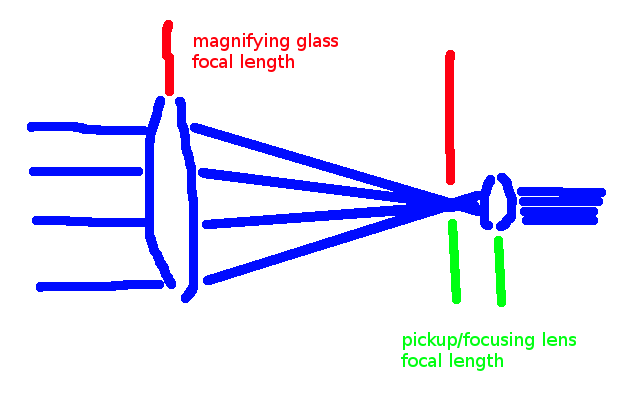
So, I thought I'd see what kind of beam I could get by using the pick-up/focusing lens in reverse... The original beam (coming from the sled, with its focusing-lens removed) is a collimated beam, but it's nearly half an inch in diameter... not too useful. The focusing lens has a focal-point of something like 1-2mm (roughly the distance to the disc's surface), so I did some rough sketches that suggest a pretty narrow beam could be formed by inserting a lens (magnifying glass) with a much longer focal-length, and matching the two lenses' focal-points.
![]()
So, it seems to me, the ratio of the magnifying glass's focal length to the focal-length of the pickup/focusing lens determines the ratio of the input beam diameter to the output beam diameter... Since the pickup-lens has such a tiny focal-length, it should result in a tiny output beam. Further, since the magnifying glass has such a long focal-length, it means the rays output by it have a pretty shallow angle and won't have much chance to diverge between the focal-point and the pickup-lens. It also seems to me the entirety of the beam will enter and exit... none of it will be lost around the edges of either lens. (Note that in the DVD drive, quite a bit of the wide beam just reflects off, or even completely bypasses, the pickup-lens's focusing mechanism... seems there's a lot of lost light in the original mechanism: between the wide angle of the laser-diode and the distance from the collimating lens, the light that misses the focusing-lens, and it's also polarized, doesn't that block a tremendous amount, as well? Might have to remove that polarizer...)
Anyways, experimenting, still, with a regular DVD (not DVD-Burner) diode:
![]()
And, lookie here, the "third-hand" I seldom find a use for not only has a purpose, and not only has a magnifying glass (which I'd forgotten), but also the magnifying glass was already adjusted to pretty much exactly the right position. Weird.
Powered-up, almost got it aligned, then the diode burnt out. My diode grave-yard is getting quite large. On the plus-side a "burnt-out" laser-diode still glows (quite dimly, and requiring tremendously greater power), so I was able to continue with the experiment.
The result? The dot is definitely larger than it is at the focal-point (duh), but it's still quite small. Maybe it'll work. OTOH, now that I think about it, if the focal-length of the pickup-lens is, say, 2mm, then that means the equivalent (or better) "beam" diameter could be achieved over a 4mm distance (2mm from either side of the magnifying glass's focal point) without the pickup-lens... That sort of manual-focus is surely achievable by-hand, even if the surface is wonky. So, that's something to consider. (Also, does the difference in travel-distance from the waves at the outer-diameter vs those in the center traveling through the system affect the output beam's coherence?)
Also, thoughts on the bipolar-stepper motor microstepping strength-improvement question... I think I get it, but I'll save it for another log-entry.
-
TODO: Microstepping
09/13/2015 at 00:06 • 0 commentsAlright, so I got a bit carried-away in the last log-entry where I claimed that "steppers are easy". But certainly an already-built-in stepper is easier than attaching a position-sensor on a built-in DC-motor, and designing a feedback loop...
Anyhow, I noticed that when I turned the knob too fast, the steppers will definitely miss steps, especially with *any* additional loading. We're not talking very fast, here, when compared to the speed the carriage moves back and forth when seeking data. Add to that: I'm running the motor-drivers at 12V, which seems absurdly high for these tiny motors, they should be doing fine, right? So, certainly, the DVD-drive's designer must've done something different...
I'm no expert on any of this...
...but I know that with unipolar stepper motors (the kind where there are four windings, paired together, and each pair sharing a common wire) microstepping helps tremendously. While the name sounds like it's used to rotate the motor in smaller steps, and in fact kind-of can, it has another benefit... strength. In a unipolar stepper, it makes some amount of sense... imagine you're turning on one winding at a time in a clockwise-fashion... Then only one winding is ever holding the shaft in position. And at the moment when you turn the previous winding off, and the next one on, the motor is far away from the next position, and therefore the magnetic force is pretty weak... Here it'll likely lose a step. So, one way to help that is to allow two windings to be on simultaneously, briefly...
E.G. Only the first winding is powered. The motor will be held in the first position (the first step). Now turn on the second winding (leaving the first on). Now the motor will be held halfway between the first and second positions/steps. So, we've half-stepped. AND we have the benefit that two windings are powered at the same time, which means there's a reasonable amount of magnetic holding-force. (Note, again, that without half-stepping, there would be no way to have any holding force anywhere inbetween two steps. But the motor is a physical object, it doesn't just teleport from the first step to the second, so without half-stepping, it would be very weak between every two steps). Great!
Actually, that's pretty much it. Microstepping can take it a bit further by lowering the power on the first winding and increasing the power on the second, so say you've got half-power on the first and full-power on the second, the motor might hold somewhere around 3/4ths of the way between the two steps. Do this sorta thing a bunch and you've got some pretty smooth motion AND holding-force in all the inbetween positions.
BUT, what I don't quite get, is how a bipolar stepper could be stronger if it's microstepped, or even *how* to microstep it. First of all, it seems to me, the de-facto means for driving a bipolar stepper is to use quadrature and H-Bridges that alternate the polarities of the windings, rather than turning them off and on. Typically, both windings are *always* on in one polarity or the other. So we've already achieved the benefits of the half-stepping case, discussed above, right?
(And here's where I get further confused, because... doesn't the electrical polarity of the winding affect the magnetic polarity? So, then, the point must be that the motor's shaft is attached to something already magnetized, which the windings either attract or repel... Right? Yet, I'm almost certain I've read that unipolar stepper motors (as in, "all") can be converted to a bipolar by simply tying the loose wires in each pair together... Except, wouldn't that require that its rotor be magnetized, which isn't necessarily a requirement for a unipolar design...? Or maybe it's that all rotors are magnetized... but I'm almost certain, again, that I've seen unipolars swapped around in both common-positive and common-negative configurations... which would mean in one case the powered windings would *attract* the rotor, and the other would *repel* it, the former would certainly be stronger! Anyways, something to ponder...)
Anyhow, apparently, microstepping not only exists (which I figured it did) for bipolar steppers, but it *also* adds to the strength of a motion... according to this page:
Now, that page gets a bit too technical for my liking... Seriously, we've got to measure the current just to be able to microstep? I think there's a halfway inbetween; somewhere between the "ideal" engineered method, and the caveman's single-stepping approach... Something that'll work pretty good, while still being somewhat easy to comprehend... I figure this: Just think of it like PWM... (Except, in this case, the winding's not off or on, it's forward or reverse-polarized.) Then just think of ramping up that PWM on one winding and ramping it down on the other. Pretty simple, really... No current-measurement necessary. And, frankly, not even needing to use a sine-wave (though surely that'd be more effective). I've done this with unipolars, and was quite pleased with the outcome, but this'll be my first attempt with a bipolar. It might go sour, who knows... Those motors are getting quite warm already... maybe current measurement will be in my future.
This image is from that page:
![]()
If I get the explanation correctly, VREFA/B are the *measured* voltage across a reference-resistor, thus representing the current drawn by the winding. The explanation makes it sound like we want to control VREFA/B... I guess, technically, in the long-run, that's what we're going for. But without a feedback loop that seems a bit difficult. And adding a feedback loop seems like a lot of work... We've got direct control over the polarity of the outputs to the windings... Switching that quickly, e.g. via PWM, that's kinda like direct control of the voltage going into the windings. We could probably look at the windings like an inductor and use math, but I have a feeling the motion of the motor would change it from the ideal inductor equation a bit... Further, the explanation in that article suggests that there may be reason to use different curves than a sine-wave, for different motors/loads. (In other words, obviously, it doesn't have to be a perfect sine-wave, heck it was a square-wave before). Why not just consider the plots labelled Current A/B to represent the PWM value...(where the bottom of the wave is PWM=0%, the top is PWM=100%)? That seems to make sense to me. And, further, I don't want to deal with a sine-wave. Why not triangular...? This is all basically what I said before the image, now I'm kinda wondering why I put it here to confuse us.
-
ramblings on precision and non-steppers
09/12/2015 at 23:10 • 1 commentThis was a long-winded response to a comment/question by @alpha_ninja regarding the precision attainable with sled-mechanisms driven by DC motors, rather'n steppers. It seems rather irrelevent, now that I've discovered that most DVD (vs CD) drives use steppers... but I'm still pro making use of those mechanisms for something...
This is based entirely on my own observations, and could be completely flakey... frankstripod's link looks to have some good general guidelines.
The HaD blog link (http://hackaday.com/2014/05/31/poor-mans-3d-printer-looks-rough-prints-great/) uses drives with steppers and avoids motors from older drives.
These notes, below, are also regarding actuators based on DC-motors (vs steppers).
*Some* drives in my collection have various position-detection schemes (some have none), apparently generally attached to the motor-itself. One has hall-effect sensors that appear to be in quadrature. Another has an optical encoder wheel (but no opto-electronics were installed!) with ~50 slots. Most don't seem to have any position-detection on the linear-actuator, so I assume they must use positional-feedback based on the CD/DVD's "tracks". Their read-heads generally have a voice-coil that can move radially (in the direction of the linear-actuator) at least a couple mm in each direction, which suggests the linear-actuator can be expected to get to a position within *at most* a few mm. That's pretty low for most 3D/2D systems we might be interested in (laser-etching, *cough* 3D-printing *cough*). Add to that: The motors are usually gear-reduced *dramatically*... some seem to have a series of gears, others seem to have worm-drives. The former (gear-reduced) are likely to have quite a bit of "slop"/backlash. OTOH, they also often seem to take that into account by using measures such as spring-loaded double/stacked gears... With so much gear-reduction, even low-precision position-*detection* *at the motor* c/would result in pretty high position-accuracy (vs precision) at the actuator.
As for *precision*... that remains to be seen... *early* experiments with a *really low [positioning] quality* DC-motor shows it's definitely possible to get positional-precision control of 1/6th of a rotation. Gear-reduce that as much as these actuators do, and it might be plausible to expect fractional-mm precision/accuracy. Add to that the fact the motors used in these actuators are quite a bit more positioning-friendly (magnetic poles at 1/6th turn?! BAH!)... I think it's possible. *I* (whoever I am) think it's possible to squeeze quite a bit of precision out of these things.
Now... HOW?
We're talking (DC) motors likely rated for something like 3V... Lets control 'em with 12... Those motors with strong magnetic poles(/pulls) at every 1/6th turn... those poles could likely be compensated-for by pumping up that voltage AT those poles. (see: early-early experiments at: https://hackaday.io/project/6892/log/24550-pwm-vs-pulse-density-modulation-power-supply) treat those poles a bit like a stepper-motor in microstepping-mode. It'd be hard on the motors and hard on the motor-drivers, but likely doable with today's [non-bulk-cost-optimized] technology.
(Note that manufacturers try to shave *every penny* in such things made in the millions, whereas nowadays the technologies available to the general hobbiest are generally less-optimized to the specific purpose, and therefore often of higher-general-quality to appeal to a wide-range of projects, while still remaining within a "hobbiest budget." E.G. manufacturer plans 5KHz PWM to drive a motor: uses H-bridges that have switching-speeds no higher than 10KHz... Hobbiest wants "PWM" [motor, speaker, LED, switching-power-supply, who knows] expects it to "just work like <so-n-so> did" gets "H-bridges." They happen to handle switching-speeds of 50KHz+)
So, yes, hard on the motors. Yes, hard on the H-bridges... in the sense that it might be smart to add a heatsink where it wasn't required before, and probably won't last for 100,000 hours of usage (but what DVD drive does?)... But, more importantly, *doable* and probably not much more (if at all) expensive than the over-spec'd devices already in wide-hobbiest-use. E.G. Again. (I assume) microstepping is used on stepper-motors used in most 3D printers... Microstepping requires fast switching speeds. Implies Dual-H-Bridge-chips (rather'n individual MOSFETs). Well-suited for TWO DC-motors.
SO, precision: Surely doable... Might need some feedback systems not originally-installed. Could probably be acquired from other "junk" laying around (ball-mice encoders...? Maybe even optical-mice?)
And, let's also take into account *other* potentials: E.G. say we're making a simple 2D laser-etcher using an old DVD-burner laser... say we leave it mounted in the original head-mechanism... which... just happens to have a high-precision voice-coil positioner... our motors might only get 2mm accuracy, but that voice-coil could do the rest. A bit of feedback... maybe hacking into the pick-up and some interferometry (since our DVD doesn't exist to read the tracks for positioning)... Absurd, but plausible. Or, what if we mounted the etcher/burner-head face-down, and attached another head facing the other direction with... A DVD. Used for nothing but positioning of the head(s).
Absolutely.
Maybe not *cough* 3D printing *cough* (or maybe?). But definitely some amount of amazing positioning precision + accuracy.
BOOM. -
Driving them [stepper] motors...
09/11/2015 at 15:58 • 0 commentsUpdate (9-22-15): NOTE: it's *much easier,* probably, to use the circuitry as-is from an old (IBM-compatible) floppy-drive. Two pins on the drive's connector are for step and direction.
Though, there may be some resolution limitations (no microstepping). See this "Fail of the week" which actually isn't much of a fail at all: Fail of the Week: Laser cutter that makes jagged edges | Hackaday
(More Updates at bottom)
Well, since I've burnt-out or otherwise damaged a few diodes in the last few days, I've noticed one thing in particular... It seems most DVD drives use stepper-motors rather than DC motors to position the head. Apparently my collection of scrapped drives shown in one of the earlier logs must come from CD drives.
Fine, steppers are certainly easier to work with. So easy, in fact, that I'm using nothing more than a motor-driver (Dual H-Bridge) chip and a quadrature-knob to move the motor in the following video (no processor!).
This stepper driver was found in old Macintosh floppy drives (and likely elsewhere). It's in a 16pin DIP, which is perfect for prototyping/breadboarding. It takes a quadrature input (like used in volume-knobs or the scroll-wheel in your mouse) to move a bipolar stepper motor (the kind that only have four wires, often found in floppy-drive and DVD-drive sleds).
Here I've wired the knob directly to the motor-driver, no processor required.
This particular chip goes by three different part-numbers I've located, so far... Sony [CX]A1035, Toshiba TA7774P, and Hitachi HA13421
(use the HA13421 datasheet, it's the most intuitive).
In this video is the CXA1035 (I haven't tested the others, yet).It also appears to come in other packages, including surface-mount. But I've probably a dozen old Mac floppy drives, and they all appear to use this chip in DIP form...
And, I know you're wondering... Why didn't I use the motor-drivers from the DVD drives, themselves...? Well, first, one drive's chip wasn't documented. The other two drives have (different) multi-purpose chips which look quite handy, but have *way* too many *tiny* pins to work with... One was 58 pins, if I recall correctly. It handled the "sled" motor, the spindle motor, the eject motor, and the focus/tracking coils. I need two for two axes, and since those chips were different, it would require that much more effort to work with them. Why not the L293? Well, I don't have any, A. And B, I don't have any money. And C, I don't have to wait for them. And D, now I know I have a dozen chips that do the job quite nicely and will be handy for other projects down the line. And E, of course I'm looking for some amount of justification in having kept around 12 Macintosh floppy drives for all these years. But they do have a wealth of cool things in 'em... The eject-motors are especially nice, highly geared-down, and modular. The "sled" motor unit is also quite nice, most are a contained unit with end-support bearings.
Oh, if you're thinking about using a different driver, I hear the SN754410 might be a good choice. Or, there's the L293D (note the D... don't bother with the L293 *without* the D, as it requires a LOT of extra components).
Next step, wire 'em up to the DVD sled motors... Why didn't I do that for the video? I'll do another and add it to this post.
----------
Here's the DVD sled in motion...
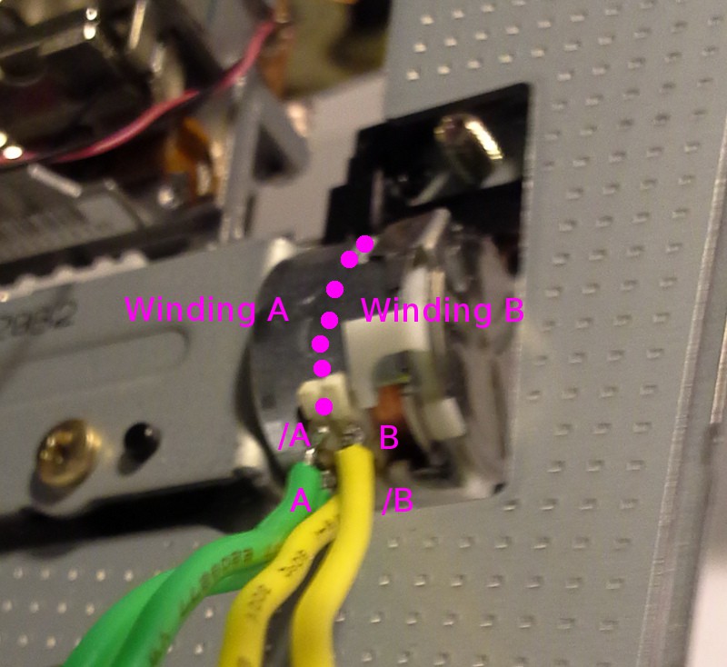
There seems to be a commonality amongst steppers of this sort... The windings seem to be "stacked" one atop the other.
I'm not certain, but I believe if you swap /A and A, and/or /B and B it merely reverses the direction. This is how I have it wired-up to the driver's outputs. (Is it possible to accidentally wire it up such that you'd get one step in one direction then the next in the reverse...? To-Ponder... but I don't think so).![]()
Also, don't use wire this large, especially solid, to connect directly to the motor's pins... Those pins are held-in the plastic, if you melt it with too hot a soldering-iron or too long keeping that heat there for such large wires, that post will lose its holding-strength, and you'll eventually rip out the tiny winding wire.
(If you read this before this update, there're a couple changes above, re: L293 vs. L293D... along with some additional rambling).
----------------
Update (9-12-15):
Further experimentation with the knob suggests that we'll be needing microstepping. I'll go into it more, later. But, the gist is that the motor is quite weak at "high" speeds, and definitely misses quite a few steps.
Again, without microstepping, it might be much easier to use an old IBM-compatible floppy-drive's circuitry. Seriously: Step and Direction.
-
Solar Irradiance and comparing incoherent vs coherent "power" + CD Diodes, maybe + burn speed -> mW
09/10/2015 at 14:53 • 4 commentsUPDATE (12-10-15):
WARNING: HORRENDOUS MISUNDERSTANDING MAY FOLLOW!
Take all bits regarding mW vs. mA with quite a bit of speculation!
(new log-entry to follow).
----------OldNote:
This log has changed quite a bit since its introduction... all additions are at the end, including burn-speeds vs mW ratings, and possibly using the CD laser as well as the DVD for extra oomph.
-----------
There has been discussion as to whether a laser diode is particularly effective, considering those in a DVD drive border on around a quarter of a watt...
For comparison: https://en.wikipedia.org/wiki/Solar_irradiance suggests that in 2011 "The most probable value of TSI representative of solar minimum is 1360.8 ± 0.5 W m−2"... so I'm no expert, and didn't read thoroughly enough to know what TSI is, (probably Total Solar Irradiance? At the surface of the earth...?)
Just throwing out some random-math... a typical magnifying-glass is, what... 5cm in diameter... so that's ~20cm^2... and if I recall my dimensional-analysis, one 1cm = .01m, but 1cm^2 is .001m^2... so 20cm is .2m, but 20cm^2 would be .02m^2?. Sure, let's go for it...
So, a magnifying-glass can set fire to paper... with 1360W/m^2 * .02m^2 = 27.2W...?
I'm trying to find some comparison between coherent light vs incoherent, in terms of power-transmitted... 27.2W from incoherent light might be equivalent to something smaller, with coherent light... but I don't really know what to search for.
Regardless, say you've a 100W LED and focus that with a magnifying glass... seems like it'd set fire to something, to me...
So I've managed to burn out several laser-diodes, now... but also managed to find a 20x DVD burner in a computer I apparently forgot about (and here I thought I'd be stuck with 12x!)... so probably 275-300mW? I definitely recall getting some "etching" in a piece of black electrical-tape with my old 16x laser...
I'm almost thinking of getting a high-wattage white LED and shoving it in a dead DVD's optics assembly... to see what'd happen. Seems to me the laser-diodes have roughly the same "viewing"-angle, so the optics-assembly would roughly create a parallel "beam", and then that's easily refocussed to a point with a magnifying glass (as shown in a previous log). Some power is wasted due to incoherence (how much? Seriously, if 250mW coherent can do what it did, certainly 10W of incoherent could match that... right?)
-----------
Here's something, and may allude to why my search has been elusive...
It really all depends on the material itself, whether it's crystalline or not, the grain size, grain size dispersion, grain shape, etc.. It's hard to say exactly what will happen in advance, even if you know all these things.
On the other hand, if the material is 'dark', i.e.: a good absorber, at your wavelength, you probably won't see much of a difference between the two light sources. For example, an ideal 'black body' is not sensitive to polarization, collimation, or wavelength."Ah Hah!
So our black electrical-tape might not care too much, or it might, depending on how good an absorber it really is... And crystalline structure, or lack thereof, might have a significant(?) effect on how sensitive any material is to coherence vs. incoherence, and thus why it's been difficult to find a simple answer...
------------
This site's handy! http://danyk.cz/laser_en.html
Duh, we could power-up BOTH the DVD burner laser AND the CD burner laser!
------------
Also, finally, a listing of expected power-ratings based on DVD speed:
http://elabz.com/laser-diode-power-output-based-on-dvd-rrw-specs/
According to Sony’s product brochure for one of their high-power red laser diodes, SLD1236VL, the diode’s output power (CW or continuous power) will be somewhere along this list:
- x4 speed recoding – 100mW
- x8 speed recording – 140mW
- x12 speed recording – 200mW
- x16 speed recording – 250mW
- x16 Dual Layer speed recording – 300mW
- x24 Dual Layer speed recording – 400mW
But, again, per a previous log-entry... I think we need to consider laser-diodes like we consider LEDs... remember the first LEDs ran at 20mA and were barely visible in daylight, whereas now 1mA is more than enough for most LEDs to be quite visible (if not bright). So we can't really determine what *current* to supply to the laser-diode based merely on its burn-speed nor its power-output... ... The recommended-maximum--found on some pages--for a 16x laser-diode is 250mA, but how they came up with that number...? Dunno. Certainly not from the mW rating! (and, actually... if the output power is supposed to be 250mW, and the diode converted every bit of its current into light-output-energy... Then shouldn't we be able to use P=VI? 250mA would relate to a 1V forward-voltage, whereas they're sitting somewhere around 1.7V, no? So that might be safely bumped-up a bit... Again, per a recent log-entry, there doesn't seem to be a distinct indicator when you're about to burn out the laser-diode, so maybe assuming Current ~= power is a safe way to go...)
---------
Here's a chart similar to the above, of Sharp's CD-RW lasers vs mW-ratings, and a couple other goodies, from: http://optics.ph.unimelb.edu.au/atomopt/diode/gh0781ra2c.pdf
CD-RW Laser Diodes from Sharp (writing speed -> optical power-output (pulsed)):
- 24x -> 160mW
- 32x -> 180mW
- 40x -> 200mW
- 48x -> 225mW
And here's a pseudo-answer to the question, above... re: mA -> mW (optical)
The Sharp datasheet for the CD-RW laser-diodes says at Po = 100mW (assumed *optical* power output), the typical current is 141mA. This makes since, WRT the question above... certainly the output-power isn't going to equal the input-power, they can't be 100% efficient, right?
Quick math: 141mA, 2.1V... P=VI = 296mW (consumed power) for 100mW optical power. Less efficient than I thought.
Another useful tidbit from the datasheet: the 225mW diode appears to be rated for "225mW (CW 120mW)." A brief search suggests "CW" means "Continuous Wave" (as directly-opposed to pulsed)... So, for etching-purposes (or laser-pointers) it seems, where the diode might remain on for long durations, it's wise to underpower that diode somewhat dramatically... (nearly half!). So, again, that seems to corroborate with the mW <-> mA presumptions used on most sites I've seen... erring on the side of preventing burn-out. Here we've a diode which apparently almost consumes 3x the power it outputs, but should only be driven at 1/2 the power it's rated to output... so then, driving it at 1:1 (mA:rated mW) leaves a little bit of a safety-buffer, right? 1/6th x power-buffer...? So, somewhere in there, it seems plausible that it's actually somewhat possible to safely drive, say, a 250mW diode with 500mA, and maybe even slightly higher, as long as it's only pulsed at a 50% duty-cycle... Which might be useful e.g. for raster-scanning.
Of course, again, these values are specific to *this* diode... And, again, this diode is Infra-Red.
And... I'm not certain I parsed this correctly, but this page is a wealth of potentially-legit info and also suggests that 100mW is "plenty fun"... but, also, suggests that 150mA ~= 100-150mW, so that seems to suggest the author was running his diodes at 150mA and causing fires with matches and burning holes in paper with something more like 60mW output-power... SO, that discussed, err on the side of protecting your eyes and whatnot, and use the lowest current necessary for any early testing... It sounds like 150mA should do something.
WARNING: Do not get crazy and start thinking about experimenting with CD-R lasers for fun! You can't *see* 'em, so you won't know if your eyeballs are burning until your retina's already ablaze.
-
Burning [out] a laser diode ++
09/10/2015 at 12:46 • 0 commentsIntentionally overpowered the DVD (not DVD-R) laser, to see what would happen... Was hoping there'd be some obvious indicator right before it blew-out so I could watch for that with the more "valuable" (harder to come-by) DVD-R lasers. No such luck.
The effect is pretty simple, it gets brighter and brighter as you increase the current, until at some point it just goes dim. After that point, apparently, there's no coming back. The diode wasn't particularly warm (it has a heatsink of sorts, the heatsink wasn't even noticeably warmer than room-temp). Just brighter and brighter then dim. Not much to work with, there.
But, there are some interesting effects to be seen. Even after the laser diode's "burnt out", it still produces light, just quite a bit less than it did before, and at a much higher current. I've heard it referred to as "a really poor LED".
Also interesting: as you vary the (now comparatively huge) current the (burnt) laser's "beam" seems to change. (see the video below).
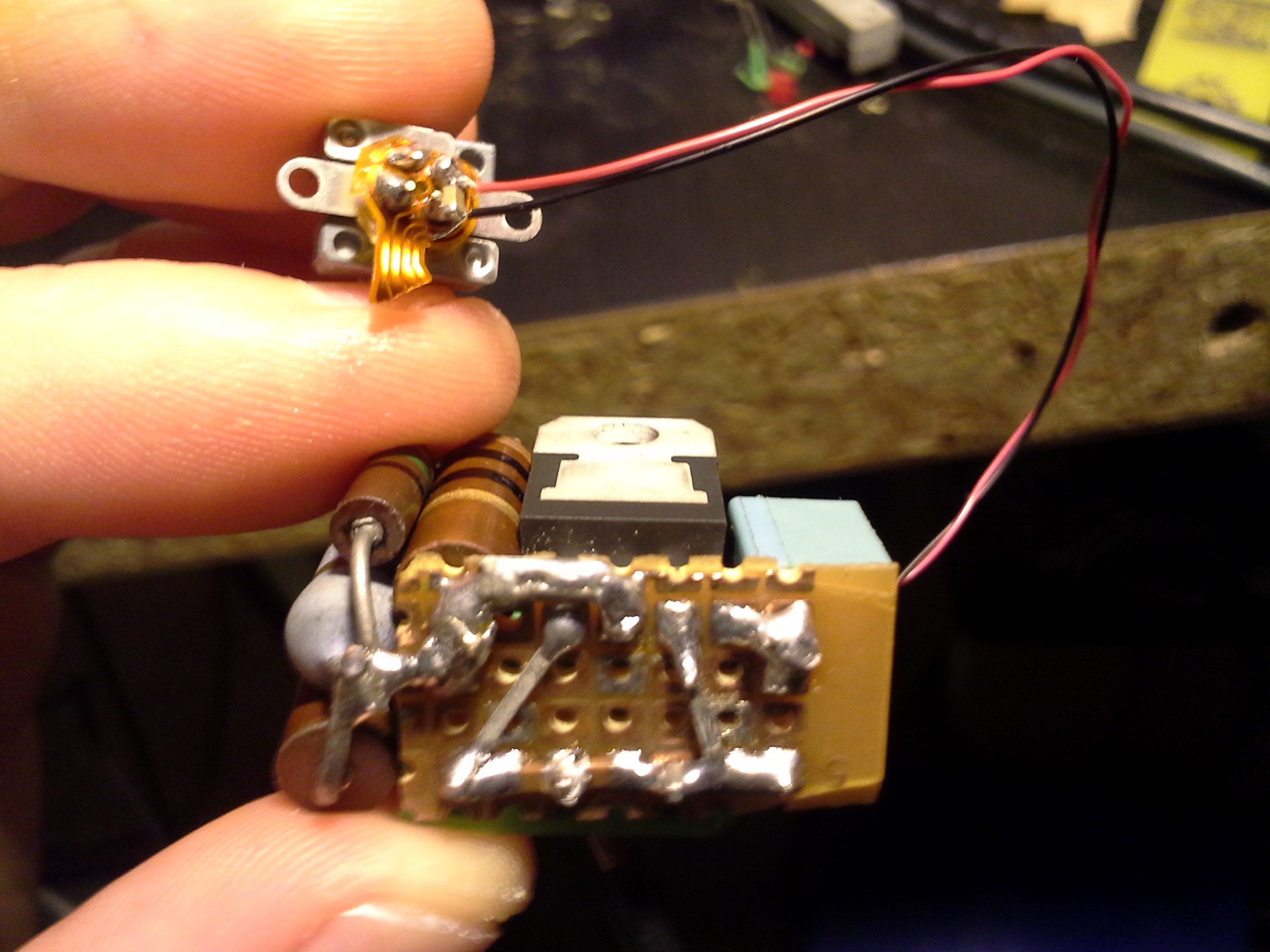
Also, per recurring demand by the infamous @frankstripod, some photos of the laser-driving circuits I've built. Wee!
Here's a couple close-ups of the circuit I built. Still no reverse-diode. Also, had to add four resistors in parallel to get the full 250mA, due to tolerance issues (some of those are 10%) and the potentiometer doesn't go all the way down to 0ohms. I used a 1uF capacitor at the power-input, and another at the power-output. I also soldered a 1uF capacitor directly at the diode. (Note in a previous log, I was wondering about a burnt laser that may have been caused by not having a capacitor *at* the diode, or many other possibilities).
![]()
![]()
Below is the first circuit I built, for experiments a couple years ago. The diode is from a 16x burner, and still seems to function. Who knows, maybe that reverse-diode is helpful. Not sure what that extra (unwired) resistor is for... Maybe I used it to measure the current early-on...? And, yeah, I was saving PCBs whenever possible.
![]()
-
Frank's Inventory
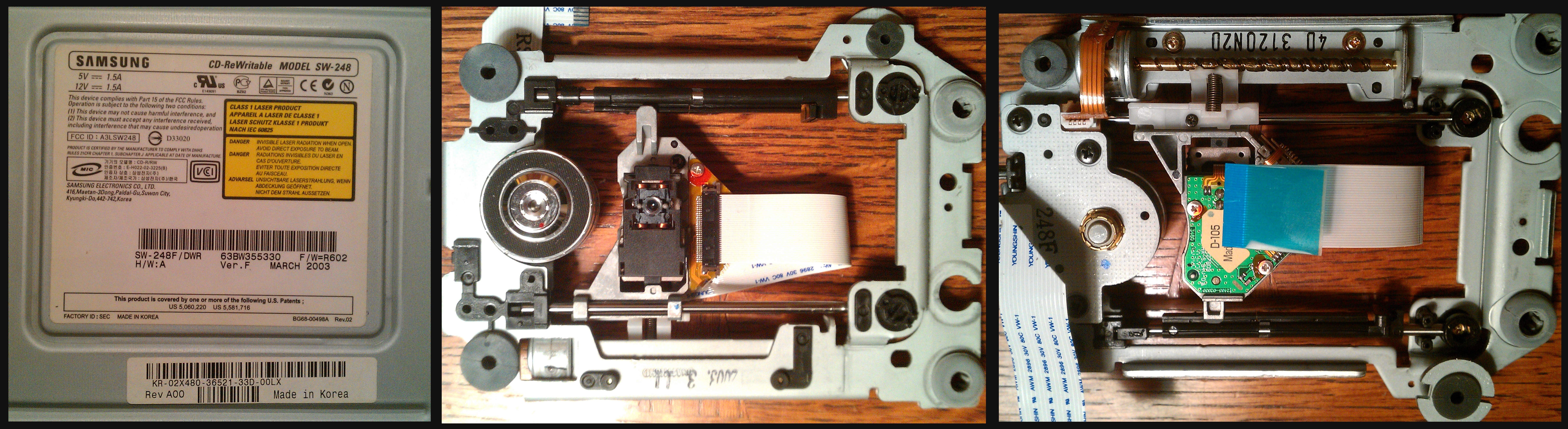
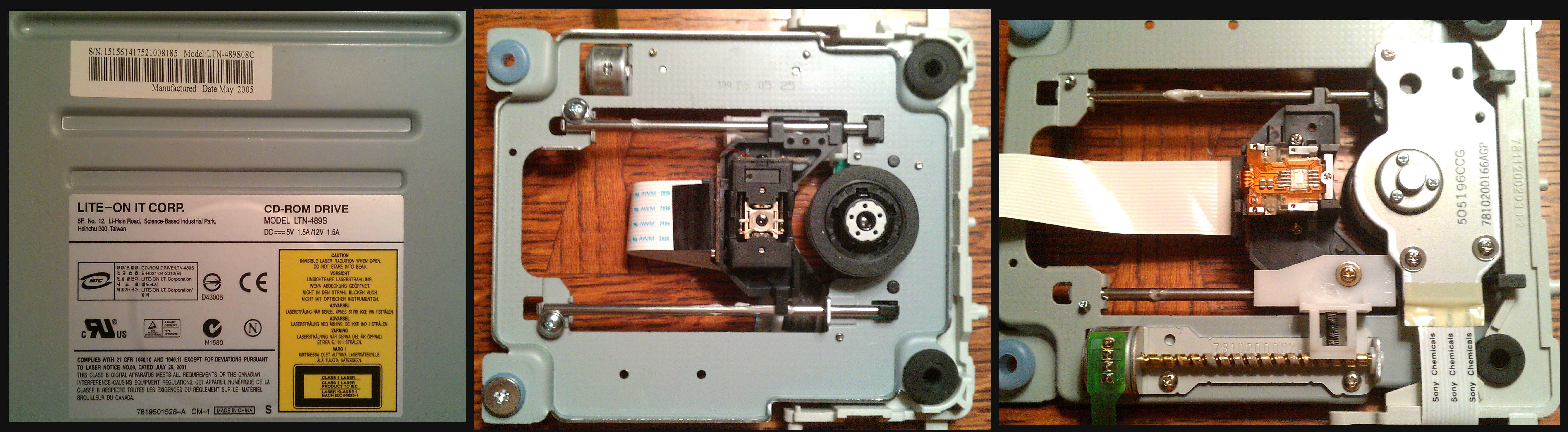
09/09/2015 at 07:56 • 7 comments- 1 Laptop DVD RW-DL + LightScribe
- 2 DVD RW-DL + LightScribe
- 1 DVD RW-DL
- 2 DVD ROM
- 3 CD ROM
- Update: Pioneer DVR-X152 External DVD RW + LightScribe
Read more for photos with model numbers...
![]()
Before:
![]()
After:
![]()
![]()
![]()
![]()
![]()
![]()
![]()
![]()
![]()
![]()
![]()
-
Laser Focusing Experiments
09/07/2015 at 14:31 • 4 commentsHere are some experiments with focusing the laser "beam"...
Note that these experiments were run with a very low current--almost the bare minimum necessary to light the laser. For these experiments, I decided to use the laser-diode from a DVD drive that does *not* burn discs... I have more of these drives laying around to scrap if I fry the laser while handling it so much... I'd be sad to fry another burner-diode (or my eyes).
This is the (bare) laser-diode removed from a DVD drive...
![]()
Note some factors...
The diode's output is NOT parallel as one expects a "laser beam" to be... In fact, it's quite a bit like an LED's output... what is that, probably a 60degree "viewing angle"?
The diode's output is NOT radially-symmetrical! There's a very distinct "long-axis" and "short axis" making it oblong.
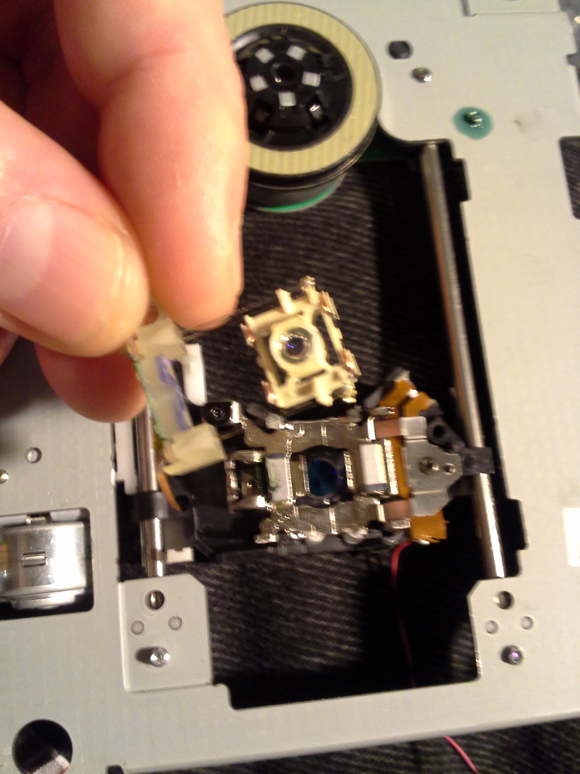
This is the laser-diode mounted in the drive's optics-carriage...
![]()
Again the output is *not* parallel. Note as I move the paper downward there is a very distinct "focal point" (roughly) where the disc should ride... (As I move it down further, closer to the lens, it becomes defocussed again). This is intentional in the design, as it allows for scratches on the disc's surface to be out of focus, and therefore not interfere with the reading of the disc at the focal-point. (More info here: physics of cd pe930103.pdf)
So we have some things to think about... If we're planning to use the laser to etch material (such as black plastic), or even if we just want to make a laser-pointer toy for the cat, we obviously need some sort of optics, (remember that first picture?). And there are some optics already installed in our system... maybe we can make use of what's there; plausibly with a little modification...
First thought: If we're etching something, it makes sense to use the focal-point in the original drive's optics... This'll be somewhat difficult, it means we've got to have *really precise* leveling/distancing with the material-to-be-cut, (just look how slightly I move that paper for it to be in--and then way out--of focus!).
With this drive, I was able to remove the focusing lens (the one that moves), with a little difficulty...
and low-and-behold directly under it appears to be the collimating lens. Nice. (I've taken apart some mechanisms which don't even seem to use a collimating lens, but maybe it's just buried way deep in all that plastic and hard to find...?) The collimating lens is responsible for turning the wide-angle "beam" coming from the laser into a parallel "beam" like we all expect from a laser. Note that's COLLIMATING not CULMINATING (though the latter seems to make enough sense to me that I had it in mind for years...). It's turning the somewhat![]()
oblong-conical "beam" into a more "column"-like beam.
![]()
Great! This is pretty durn beam-like, I tormented the cat with it for a good half-hour, and it easily goes across the room. Its diameter appears to be about half an inch, however... If you're planning to etch with this, you'll be sorely disappointed. A) All that etching/cutting power's spread out over such a huge area it likely won't heat up anything noticeably. B) it's just too low-res to do much useful with besides torment the cat or point out things on a whiteboard. ;)
Now, I don't recall where the lens in the next picture came from... I think it was an old magnifying glass. I just set it right atop the laser mechanism. Since the beam coming out of the mechanism is now collimated, it doesn't matter where we place the lens in that beam... it doesn't have to be a certain distance away from the collimating lens.
(Hey, I think there's something here about the ideal focal-point of the lens... Isn't the focal point where a point-source of light should be located in order for the rays exiting the lens to be parallel? That's hard to accomplish with real-world light sources, but here we have pretty much the ideal real-world case, in reverse. The light's entering in parallel "rays" and we can find the focal-distance based on where those rays cross at a single point...)
![]()
So, personally, I think this'd make for an easier laser-etcher than trying to run the mechanism (with the original focusing lens) *right above* the material.
A) (again) it seems like it would be difficult to keep the laser travel *perfectly* parallel with the material to be cut/etched... The focus of that lens varies dramatically with only 1mm of displacement... whereas with this lens the focus varies only slightly over several millimeters of travel.
B) Having the (original) lens so close to the material being cut/etched would probably result in its "fogging up" from the smoke released by the material... And, since the laser mechanism would most-likely be facing downward toward the material, all that smoke is going to collect there... It'd be hard to put a fan there, since it'd only have 1mm or so of space to blow in...
C) I think it's pretty durn nice to be able to *see* the material being etched/cut while it's doing-so... as well as for focusing... The DVD mechanisms would block quite a bit of the visibility.
On the other hand, it'd be pretty nice to not have to use custom optics... so, we'll see.
Another consideration, maybe, is using two lenses after the collimator. One would shrink that beam down to a point (like the magnifying glass did, earlier), then the other would recollimate that point into another, very narrow, column-shaped "beam." Plausible. Then there wouldn't be much need for focusing or leveling the bed. I've heard they don't do this with regular laser-cutters because having *so much* power in a tiny beam actually ignites the air in the beam... I doubt these tiny lasers could do that, but there may be other reasons why such a narrow beam isn't the de-facto in cases like these.
-------
Here's a link to someone's setup using the bare diode and the focusing lens: http://www.instructables.com/id/Homemade-laser-module/?ALLSTEPS
It's a pretty good setup, certainly more precise than my by-hand experiments!
I'm not sure how he managed to get a "beam" out of it, I certainly wasn't able to in my experiments. My theory is that, as I said earlier, I have taken apart some drives that don't seem to have a collimating lens... So, then, maybe the focusing-lens on these drives takes that into account...?
(Thanks @frankstripod for a bunch of ideas in here!)
CD/DVD mechanisms and cartesian thinggie[s?]
DVD-laser-etcher, dremmel-router, possibly a 3D printer? Who knows!