RoGeorge
-
Rigol DP832 Power Supply set for 20 mA can kill a LED
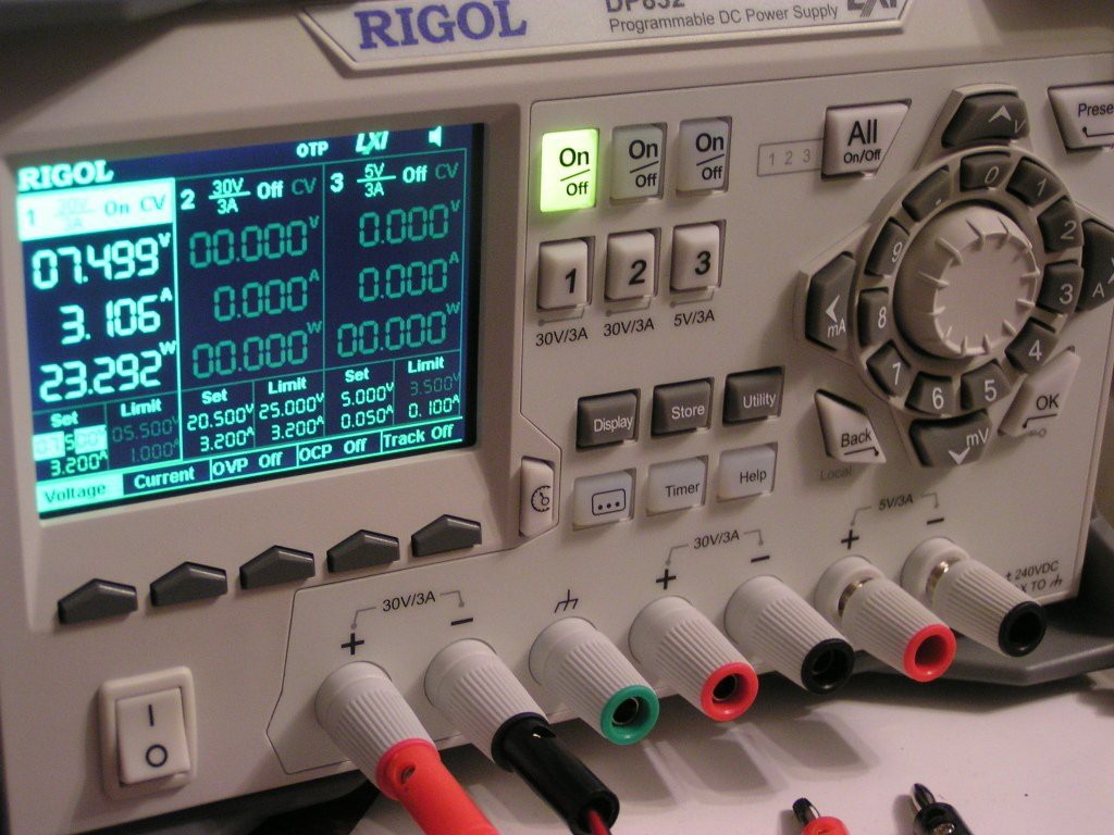
09/18/2015 at 08:54 • 6 commentsI was demonstrating the Constant Current capabilities of my new power supply, Rigol DP832:
![]() NOTE: This picture is from another project, please ignore the DP832 settings from this picture.
NOTE: This picture is from another project, please ignore the DP832 settings from this picture.My intention was to demonstrate that, if the current is set for (limited to) a 20 mA, the voltage can be set for up to 32 V (which is the maximum for this power supply), without demaging the LED. So I did like this:
- Set the maximum current to 20 mA
- Set the maximum voltage to 32 V
- Hook a LED to alligator clips
- Enable power
The LED started to lit. The power supply indicated a drawn current of 20 mA and a 1.7V voltage drop on the LED. All good.
Then I wanted to hook a blue LED, in order to demonstrate that the voltage drop is dependent of the LED color. I did like this:
- extract the first LED from the alligator clips (while the LED was on)
- pick another LED from the table and attach the first terminal to the alligator clip
- attach the second LED terminal to the other alligator clip
LED FLASHED & POPPED OUT DEAD!!!
![]()
The LED was brand new, without any scratches. The strips that looks like scratches on the LEDs plastic body are from the stress during the pop.
WTF? Can a LED pop like that with the power supply set for 20 mA?
The lower side of the junction looks like it was flipped through the transparent material. I have no idea how it was possible. Maybe the plastic has melted during the flash, then the lower side of the junction mirror was flipped with an angle of about 30 degrees from its normal position, then the plastic solidified back. I don't know.
![]()
![]()
But why did it happened?
Any power supply have a big electrolytic capacitor at it's output. While I was changing the LED for a blue one, the source kept sourcing the 20 mA, but without the LED, all the current charged the power supply output capacitor up to the maximum allowed voltage set, which was 32 V.When I connected the blue LED, the 32 V rushed through the LED, and all the energy stored in the capacitor passed through the LED junction, destroying it.
Later, I measured the current for the same setup, except this time I just shorted the alligator clips. A spark appeared, but look at the voltage drop on a 0.94 ohms wire:
![]()
For a few milliseconds, a huge current passed through the wires, with a peak of more then 18 Amps. That's about a thousand times more than the normal average current for a LED.3D Printing AVR Arduino Art Audio Automation BeagleBone Bluetooth Cameras Clock Drones Environment Hardware IoT LED Medical Music Radio Raspberry Pi Remote Control Robotics Rockets Satellites Science Security Software Virtual Reality Wearables
-
Assumption is the mother of all fuckups
09/07/2015 at 21:17 • 6 commentsYesterday I was building a headphone amplifier, and was looking for a differential voltage source. Something small, preferable a wall adapter. Any fix voltage in the interval +/-5V ... +/-15V would be just fine. Expected current 100...150 mA.
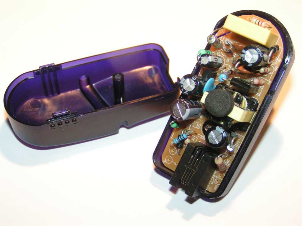
Most wall adapters from the scrap box were from old mobile phones, single voltage, 5V or less, with glued cases and no way to adjust the voltage. Still, there was one with a screw-fastened case, single voltage, 8.4V/500mA:
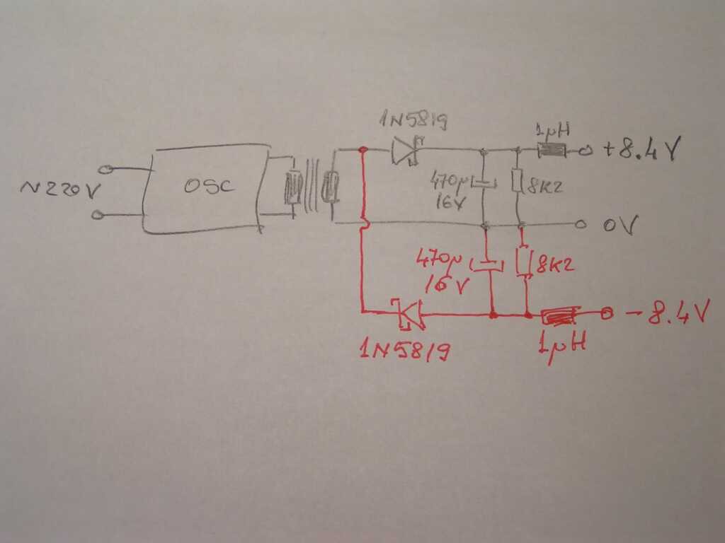
![]() It has a 4 wires RJ9 female connector (like a LAN connector, but with 4 pins only), which was perfect, because I needed at least 3 wires, but preferably 4. Even more, the schematic was very hacker friendly:
It has a 4 wires RJ9 female connector (like a LAN connector, but with 4 pins only), which was perfect, because I needed at least 3 wires, but preferably 4. Even more, the schematic was very hacker friendly:![]()
All it needs to add a negative voltage was another rectifier circuit, like the one in red:![]()
Even more, the PCB had an un-populated area in the lower voltage part, more then enough to add the 4 red components.That was too nice to be true!
When something is too nice to be true, most of the time it's because it's not!After the red part was added and everything was double checked, it was time to plug it in.
Does it worked? No.
Instead of +8.4 / -8.4V, the output was +8.4 / -25.2V. Exactly 3 times more negative voltage then expected.Can you spot the mistake?
![]()
I assumed for a symmetric oscillator, but look at the waveform.
It was not symmetric at all, which is normal for a SMPS charger with a simple oscillator.The waveform was measured after the facts, just to confirm the reason of the failure.
:o)
 NOTE: This picture is from another project, please ignore the DP832 settings from this picture.


 It has a 4 wires RJ9 female connector (like a LAN connector, but with 4 pins only), which was perfect, because I needed at least 3 wires, but preferably 4. Even more, the schematic was very hacker friendly: