lukasz.iwaszkiewicz
-
Stopwatch accuracy
05/14/2020 at 08:25 • 0 commentsI'm working on the accuracy of the stop-watches. First I performed some tests and It seemed that a lot can be improved in many areas (I'm writing an article about the process). The most important part was to use a proper temperature controlled oscillator (TCXO) which you can see below. The canned 8MHz crystal is not used right now. I'm getting 1ppm accuracy against my bench signal generator, but the final test would be to test the system against a GPSDO which is about 0.01ppm accurate. Oh, and the least precise element is the IR trigger, but still, I'm getting ~100µs precision out of it (in the lab environment).
![]()
-
Improving LCD performance
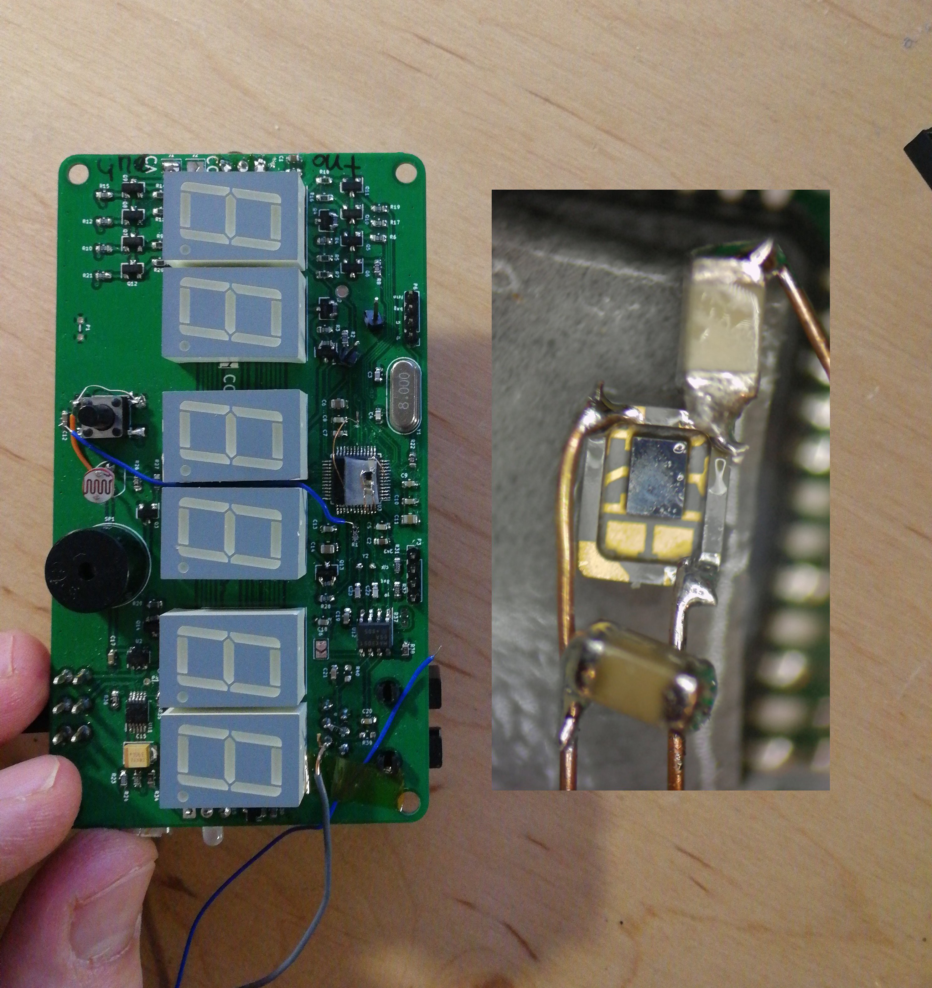
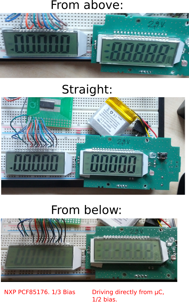
02/24/2016 at 12:36 • 0 commentsOn the picture below you can see that I have had problems with ghosting, and it annoyed me a lot.
![]() So, on the right side you have my rev. 2 prototype (second PCB layout, not counting the early bread board prototype). It is usable, i.e. one can read the LCD, but there is also significant ghosting which makes the display unreadable when viewed from angle. I tried to modify the firmware (BTW firmware is based mostly on this http://www.dataweek.co.za/article.aspx?pklarticleid=2382), but couldn't do better than this. Since I didn't know of any simple method of generating 1/3 bias wave forms on bare GPIOs, I decided to try out the cheapest driver I could find on farnell (that was PCF85176 at the time of writing : http://www.farnell.com/datasheets/1923814.pdf). And it performs much better, as you can see on the left side of the picture. Another cool thing is that now µC uses only 2 pins for driving the whole LCD, since the PCF85176 communicates via I2C instead of 16 pins which were used to drive the LCD directly. This fact will allow me to use smaller micro (STM32F042 or 72 or 70) which should be much cheaper than the one I use now. I expect that overall cost should be the same or even lower.
So, on the right side you have my rev. 2 prototype (second PCB layout, not counting the early bread board prototype). It is usable, i.e. one can read the LCD, but there is also significant ghosting which makes the display unreadable when viewed from angle. I tried to modify the firmware (BTW firmware is based mostly on this http://www.dataweek.co.za/article.aspx?pklarticleid=2382), but couldn't do better than this. Since I didn't know of any simple method of generating 1/3 bias wave forms on bare GPIOs, I decided to try out the cheapest driver I could find on farnell (that was PCF85176 at the time of writing : http://www.farnell.com/datasheets/1923814.pdf). And it performs much better, as you can see on the left side of the picture. Another cool thing is that now µC uses only 2 pins for driving the whole LCD, since the PCF85176 communicates via I2C instead of 16 pins which were used to drive the LCD directly. This fact will allow me to use smaller micro (STM32F042 or 72 or 70) which should be much cheaper than the one I use now. I expect that overall cost should be the same or even lower. -
Bare LCD
02/16/2016 at 21:21 • 0 commentsSecond revision of PCBs received and soldered. Range improved. Rough tests on cloudy weather showed nearly 10m (30ft). Must wait for summer to test in direct sunlight. Bare LCDs proved to be very difficult to drive directly (no LCD driver in STM32 at least for this kind of display). Although display works as you can see on the image somewhere in the image gallery, but there is signifficant ghosting going on when seen from angle.
-
Gerbers sent to the fab
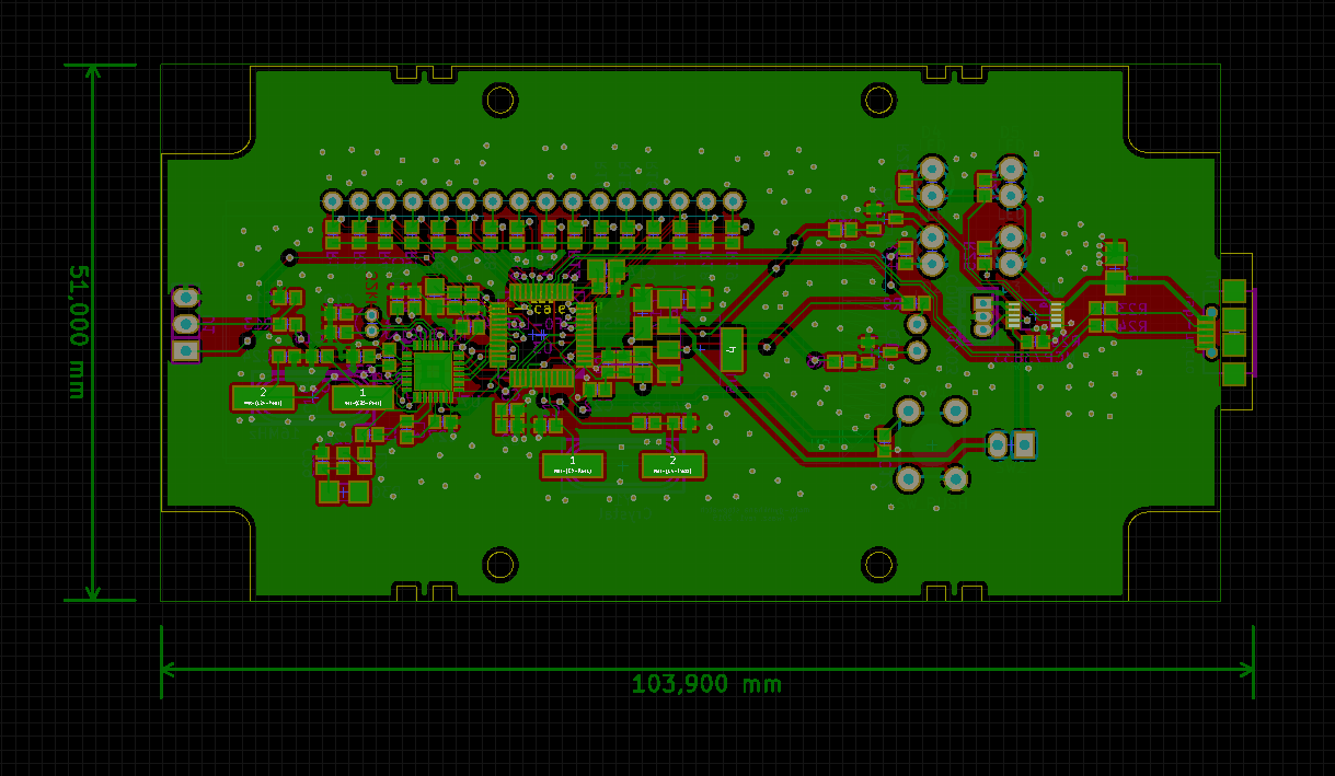
11/13/2015 at 13:39 • 0 commentsReceiver:
![]()
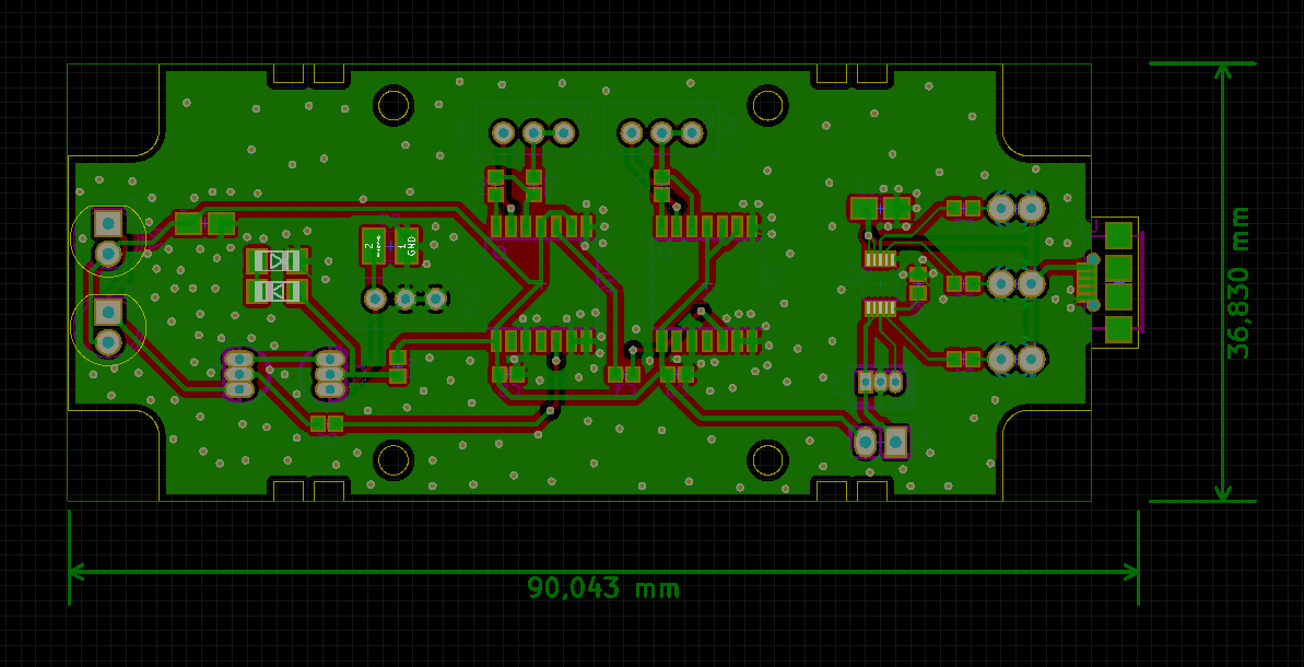
Transmitter:
![]()
And here's video how I managed to make round pcb corners in KiCad:
-
IR emitter range
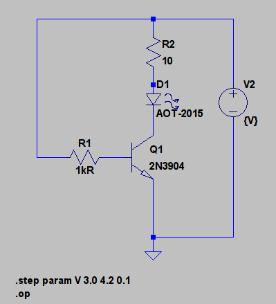
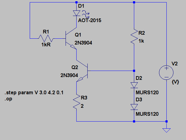
10/13/2015 at 23:51 • 0 commentsMain problem I have with this stop-watch is its photo-barrier range. At dark, everything seems to be all right, the IR emitter can be as far as 5m (15ft) away, but when I'm outside, and the weather is sunny, range decreases dramatically down to 2m (6ft) or less. This is probably due to the fact that sun emits full spectrum of very intense visible and IR light, and fools the receiver. It simply cannot distinguish IR pulses from the emitter from background IR light, even though emitter modulates the signal, and sun does not. To overcome this, I must assure, that the emitter does its best, and the pulses are strong, and exactly 38kHz, and receiver is not exposed to direct sunlight. Probably some form of lens hood on the receiver would do the job, but lets focus on the electronic portion for now. The simplest circuit I tried was this (two 4047 multivibrators are not shown, I use them to generate the signal which would be attached to R1 instead of V2):
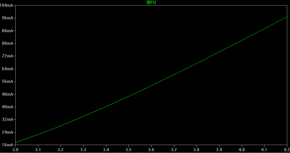
D1 is a TSAL6200 IR diode from Vishay, and can handle up to 100mA pulses, so this circuit simulates 100mA through the D1 when V2 equals 4.2V which is the max voltage a LiPo cell can provide (when fully charged). But what would happen when battery runs out to, lets say, 3.4V which is (I believe) the lowest acceptable voltage a LiPo battery can work with. LTSpiceIV (which is excellent, and runs under wine flawlessly) shows that current through the IR diode drops significantly (approx. 40mA when V2 equals to 3.4V and not much more than 55mA when battery provides 3.7V which is fairly typical for a LiPo):![]()
To prevent that, I figured out, that I should use a current source. So I came up with the following circuit:![D1 current]()
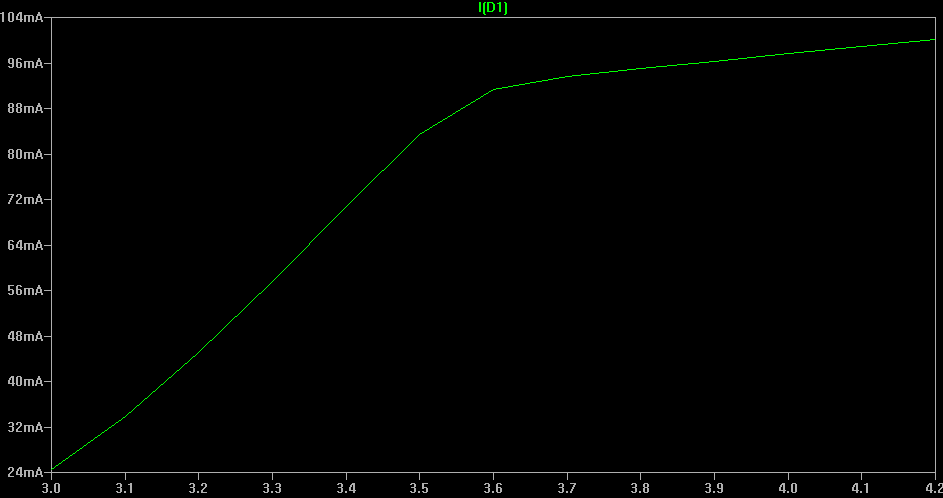
Q2 and R3 works as a transistor current source which forces approx. 100mA through the D1 and Q1. R2 and two serially connected diodes are for biasing Q2. They provide approx 1V to the base of Q2. Q1 at the other hand works as a simple switch, which again would be connected through R1 to the 38kHZ 1ms bursts source. It can instantly turn on and off all this 100mA current which lights up the D1 diode. Again LTSpice shows what would happen with D1 current when V2 voltage source runs out (from 4.2V to 3.0V):![]()
Looks better, but real life tests should be performed.![Current through the IR diode D1]()
-
LCD
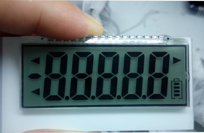
09/16/2015 at 09:00 • 0 commentsI ordered a LCD display(s) I found on AliExpress. They are $2.30 each and looks great. The only trick is, that bare LCDs are driven completely different than multiplexed 7-segment LED displays, so several more evenings/nights expected. It looks like this (photo taken by manufacturer) :
![]()
Here's the link : http://www.aliexpress.com/item/Free-shipping-5-digits-7-segment-LCD-display-custom-made-LCM-automatic-weighing-scale-size-57/32440251274.html
-
First tests
09/08/2015 at 21:06 • 0 commentsSo after 13 nights (evenings) the device was ready to test. We practice (we even have a non-formal team of friends who gather every week) every Tuesday, but I had to watch over my kid that day (I love him so much!), so I took him with me, and we came by bicycle instead of my XJ6. Weather was shitty, so only 1 other guy showed up (well, then another one came, but I was leaving) and I asked him if he could go in circles and test my contraption. It happens that he made the other stop-watch, so we had a constructive chat on the subject, and then the test begun :
Conclusions are as follows:
* Shitty LED display (oh boy the multiplexing thing almost killed me. It was 50% of the work this display). Not much visible in the direct sun. As I mentioned, I did this at night mostly, so It looked like perfect at home and at dark. But sun (and even partially cloudy weather) made it unreadable. I already found and ordered promisingly looking LCD displays (China of course), which would be much more clear, and less power hungry. Oh boy how I love compulsive purchasing on AliExpress. One click and you're there.
* Too low range. As you could have seen on the vid, the stop-watch comprises of IR emitter with brass pipe attached for beam focusing, and receiver, which has IR remote thing. http://www.farnell.com/datasheets/1734663.pdf Again, in dark it behave well, but outdoors it had problems.
Both receiver and emitter draws about 50mA and has 1000 mAh LiPo batteries.
photo sensor stopwatch
Stop-watch for moto-gymkhana and other sports with many features.
 So, on the right side you have my rev. 2 prototype (second PCB layout, not counting the early bread board prototype). It is usable, i.e. one can read the LCD, but there is also significant ghosting which makes the display unreadable when viewed from angle. I tried to modify the firmware (BTW firmware is based mostly on this