So the current global pandemic and forced self-isolation has given me a great opportunity to really dig into the Outback MATE protocol, and I have figured out all of the important details! (documented on my GitHub project)
I also started working on an Arduino-compatible library (currently far less featured) which is mostly useful as a way to convert the 9-bit MATE data to 8-bit PJON frames which mean I no longer need to use hacky methods in Python and can run things a LOT faster.
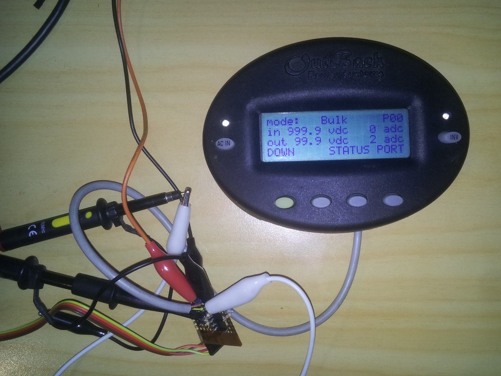
uMATE gave me a convenient way to sniff traffic between two devices and send it to Wireshark:
This has been immensely helpful for figuring out the remaining details, as I can capture & monitor traffic in real-time and compare it with the MATE readouts. It helped me discover that the MATE actually synchronizes the devices every minute or so by reading/writing specific registers - and this is how the FLEXnet DC can know the date, time, and battery temperature without actually having an RTC or temperature sensor.
I was able to discover the meaning of the remaining bytes in the MX status packet, and implemented status packets for the FLEXnet DC monitor.
Using the information that I reverse engineered, I developed a Python2.7 library that can emulate a MATE device through a normal UART port. You can find more details about it on my website blog post: pymate.
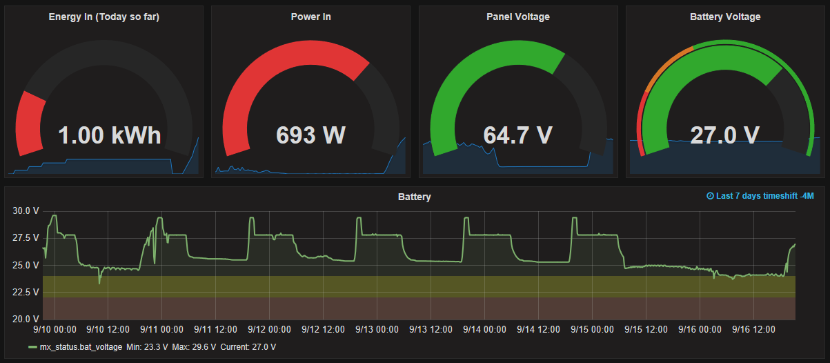
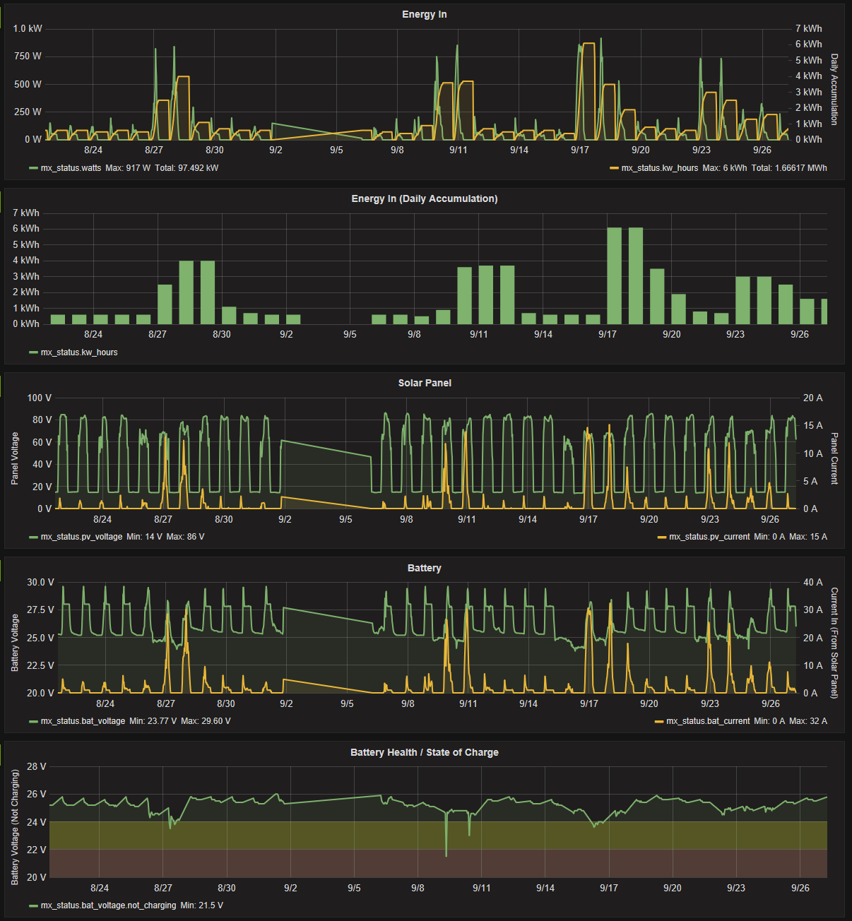
I set this library running on a small light-weight linux device (A Carambola2), which continuously collects information and uploads it to a remote server. I didn't do anything terribly fancy, just a simple python loop/queue which queries the MX inverter for status packets, decodes them, re-encodes them as JSON, and uploads them to my server via HTTP which then stores them into a PostgreSQL database.
For a while I didn't do anything more, and just left it collecting data, until I recently stumbled upon a nice open-source project called Grafana. Unfortunately by default it only supports time-series databases (TSDBs), not regular databases like Postgres. I found someone's Github fork which adds SQL support, and was able to connect to my Postgres DB with very little effort!
Now the effort of reverse-engineering their protocol has finally paid off!
The next part is to figure out how the protocol works, and the format of the data.
I started with taking some live captures in a running system (A MATE connected to an MX charge controller), and looking at what kind of packets were being exchanged. The MATE behaves as a master, and all communication is initiated by it. No data is sent from the MX by itself.
On start-up, the following packet is exchanged (presumably some sort of scan/ID packet):
TX: 00 02 00 00 00 00 00 02RX: 03 00 03 00 06
(TX is what the MATE sends, RX is what the MX sends back)
And while on the status panel, the following packet is sent every second:
It's worth noting that the first byte in both TX and RX actually have bit 9 set. I wasn't able to capture this on my PC, which just treated the 9th bit as a parity bit. This is how they denote the start of a packet
After observing a few packets, it became clear that the last two bytes were a checksum - but not a proper checksum - it was literally just the sum of all the bytes in the packet! (03+00+03 == 00 06)
There were also some obvious patterns in the TX packet, like the second byte which seems to correspond to some kind of command or packet type (02 for start-up, 04 for requesting a status packet)
I then tried matching the received status packet with the information that was currently on the screen, and was able to pick out some of the fields (status, battery voltage, pv voltage). Unfortunately the rest of the data proved elusive, but it was definitely encoded somewhere within the packet!
I decided a different plan of attack was in order, since I couldn't see any other obvious patterns in the data. I started writing a simple MX emulator in python, communicating through my MATE adapter mentioned in the last progress log.
It was able to spoof packets to the MATE, and I could then see the result on the screen and figure out what each byte did (or at least every byte that was visible on the LCD). By doing this I was able to figure out almost all of the status packet so I could correctly decode one sent from the MX unit itself. (Since the goal of this project is to replace the MATE and talk directly to an MX unit)
Spoofing the status packet sent to a MATE unit
At this point I decided to try spoofing some other devices which I did not have access to, such as an FX inverter, a Hub, and a FlexNET DC monitor.
This was a bit trickier to spoof since I had no idea what kind of data the MATE would expect. Luckily I discovered that the MATE would actually tell me if the packet had an error if it was too short, so I just kept padding 0x00s until it reported no errors (at which point it showed all 0s on the LCD for each read-out). I was then able to poke each byte and see what effect it had on the LCD, and mostly determine what each byte did.
The spoofing code I used is available in my python library, but the MATE adapter needs to have the RX/TX swapped since it will be connected to the MATE, not the MX/FX unit.
The next thing I discovered was that some of the other LCD screens sent a separate packet, which appeared to obtain the value of one specific register (eg. battery voltage, relay status, etc.):
TX: 00 02 00 44 00 00 00 46RX: 03 00 12 34 03
And I also discovered a similar packet was sent when I tried to control something (the MATE allows you to turn an attached inverter on/off):
TX: 00 04 00 61 00 00 01 65RX: ??
The full details of what each byte represents is available in my python library
-The Outback system uses a proprietary interface to connect the MATE to one of their devices over standard Cat5 cable. It can talk to multiple devices through the use of one of their proprietary hubs, or can just connect directly to the device. The RS232 protocol from the MATE unit is documented, but this proprietary protocol (what I call from now on "MateNET") is completely undocumented.
Before I started attempting to reverse engineer, I guessed that the protocol would use some sort of standard protocol over RS485 - but I was wrong! After looking at the signals in a live system it was clear that the interface was not differential at all, it was just standard serial (UART) at 0-24V logic levels!
The actual format of the bus is 9600 baud, 9n1 (yes, 9 bits of data - the 9th bit is used to signify the "address" byte, or the start of the packet)
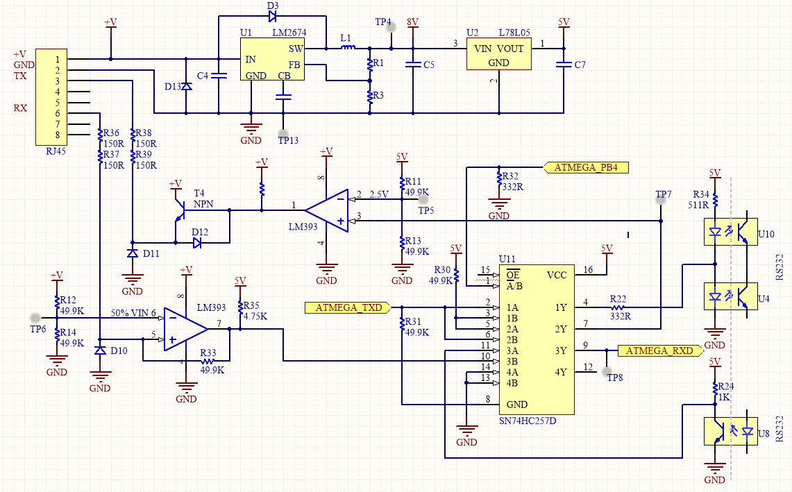
To figure out the exact pinout, I decided to reverse-engineer the MATE circuitry (since I had easy access to one I could pull apart). The circuit is pretty basic, it consists of a standard ATMEGA32, some EEPROMs (for logging), an RTC, a buck converter, RS232 isolation, and the MateNET interface. What suprised me is their use of a logic mux to switch between RS232 and MateNET - obviously because the ATMEGA32 only has one serial port!
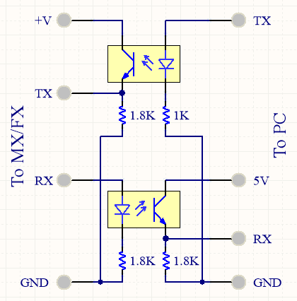
I have replicated the circuitry related to the MateNET RJ45 port below: (This does not show the EEPROMS/RTC/ATMEGA)
Note that these use the standard ethernet pairs (Orange/Green pairs).
Creating an adapter from the above schematic was easy. I decided to forgo the comparators, and just use some opto-isolators (which also guarantees my linux board will be isolated from the charger)
This opto-isolator can replace the MATE, or a MX/FX unit (for testing - this allowed me to poke values at the MATE and helped me figure out the packet formats with much finer detail than I could have by simply capturing and observing them!)
To connect the adapter to an MX/FX unit using an RJ45 cable:
 Jared Sanson
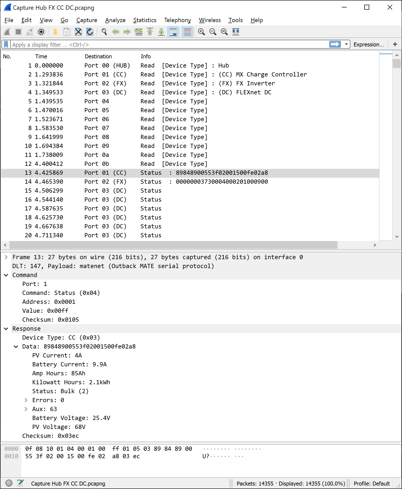 This has been immensely helpful for figuring out the remaining details, as I can capture & monitor traffic in real-time and compare it with the MATE readouts. It helped me discover that the MATE actually synchronizes the devices every minute or so by reading/writing specific registers - and this is how the FLEXnet DC can know the date, time, and battery temperature without actually having an RTC or temperature sensor.
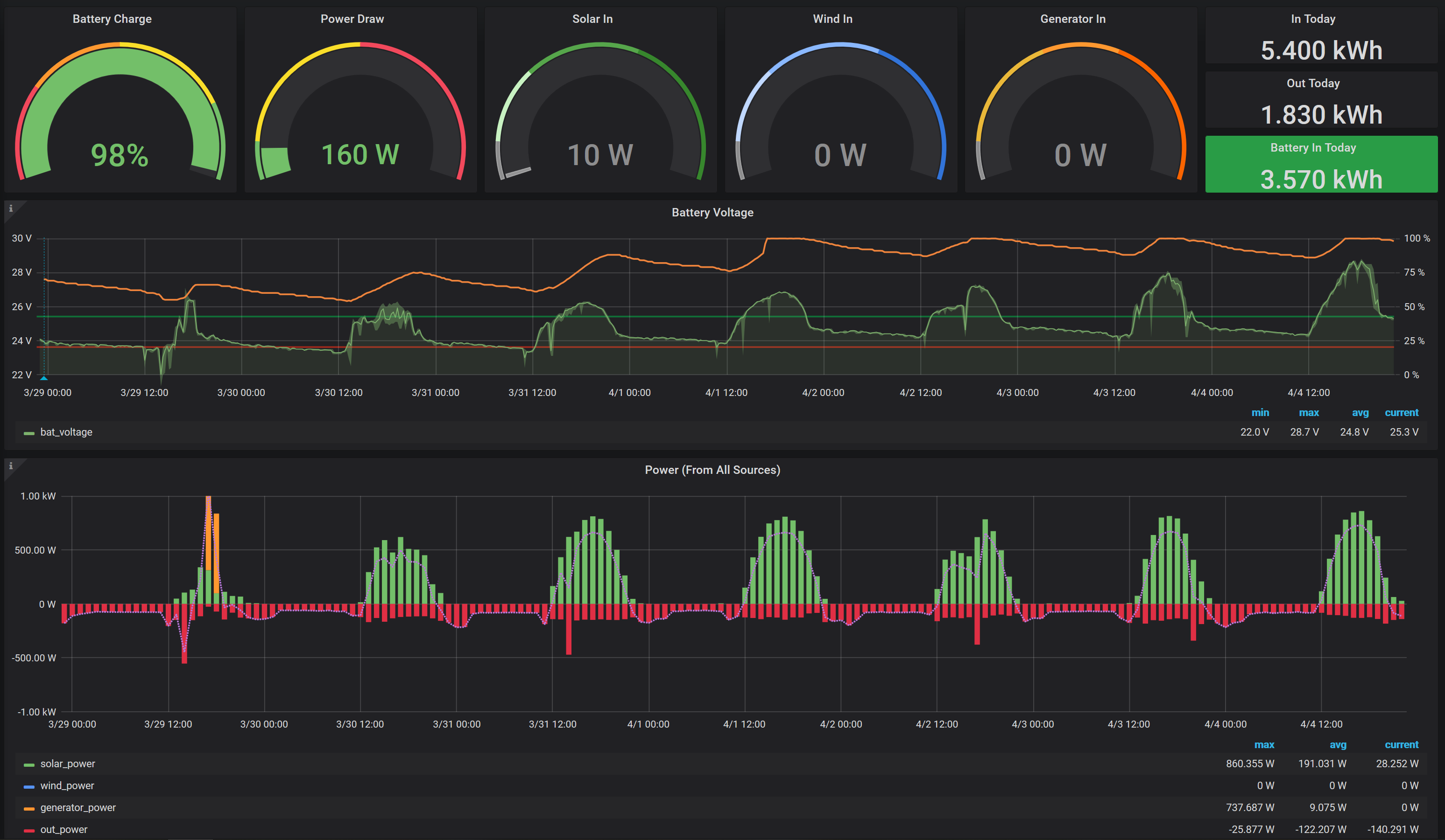 Repos: