 DeepSOIC
-
1Step 1
solder a chain of 10M resistors.
![]()
-
2Step 2
Coil the chain:
![]()
-
3Step 3
![]() Place the coil between two plates.
Place the coil between two plates. -
4Step 4
Solder that to a pcb (I made one by dremeling off some copper). Solder the 100M resistor, and a coaxial wire.
![]()
-
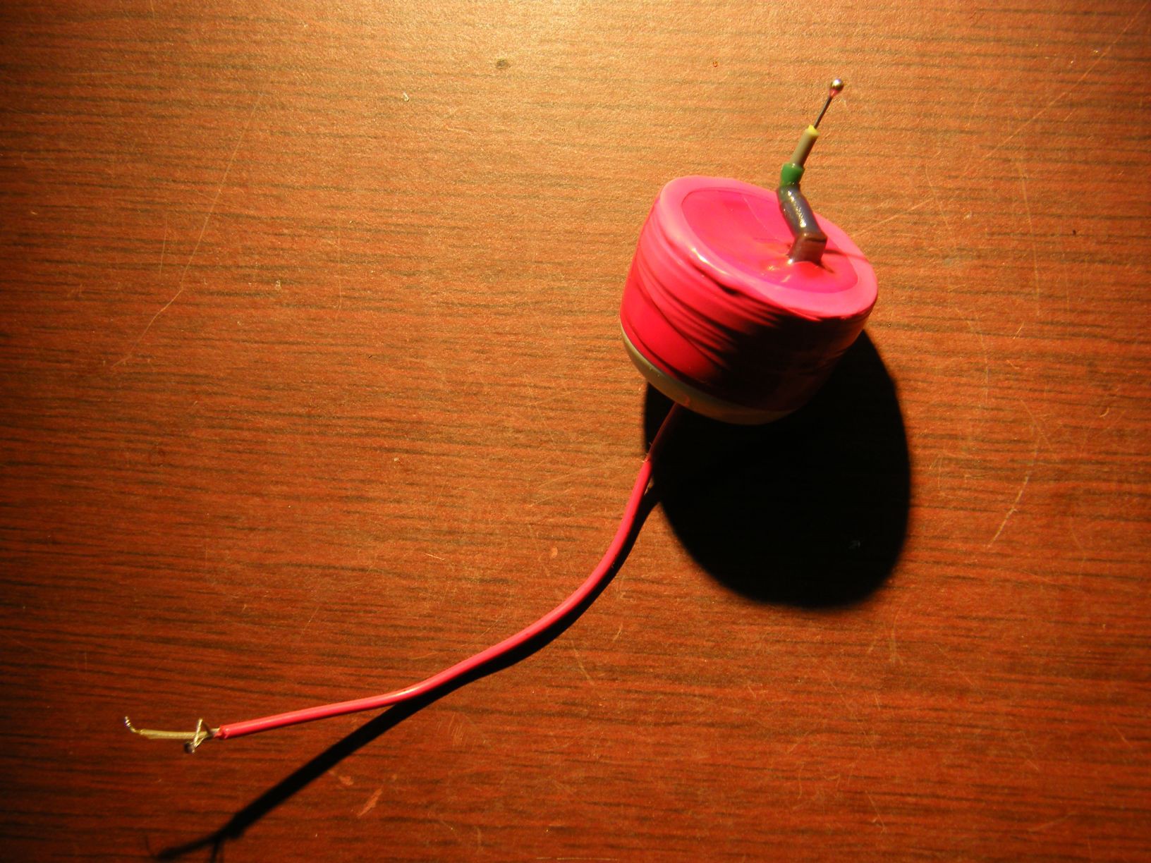
5Step 5
Solder a pin to serve as the probe tip, put some heatshrink around it and the pcb. Don't cover the capacitor-divider, as it needs to be potted.
Put the divider into a metal cup with a hole at the bottom.
-
6Step 6
Pot it! I have put some hot-snot glue, and placed it into a cooking oven. Make sure the hole at the bottom of the cup is plugged so that the 'pottingcompound' isn't going to leak away
![]()
-
7Step 7
Add some extra shielding (I don't think it's all that important, actually). The shield should reliably screen low-voltage parts of the divider from any external electric fields (except those coming from the tip electrode, of course). This is to make the capacitance between input and output fixed.
![]()
-
8Step 8
Add some more insulation
![]()
-
9Step 9
Add a capacitor across the output, to compensate the divider in a manner similar to the regular oscilloscope probe divider compensation. You need to try a number of capacitors, to obtain a good-looking square wave output. Make sure the connection between the divider and the oscilloscope probe is shielded as well, you don't want any capacitive coupling from the input
Use low voltage for this part, high voltages are DANGEROUS. This part doesn't require high voltage.
-
10Step 10
You are done! But remember: always use extreme caution when dealing with high voltage!!!
 Place the coil between two plates.
Discussions
Become a Hackaday.io Member
Create an account to leave a comment. Already have an account? Log In.