 Jac Goudsmit
-
11Step 11
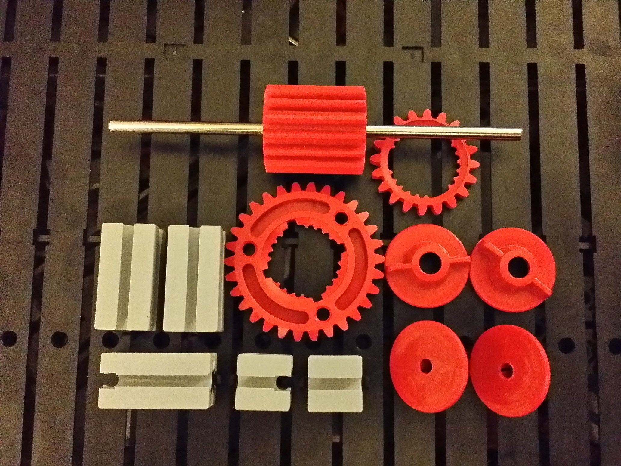
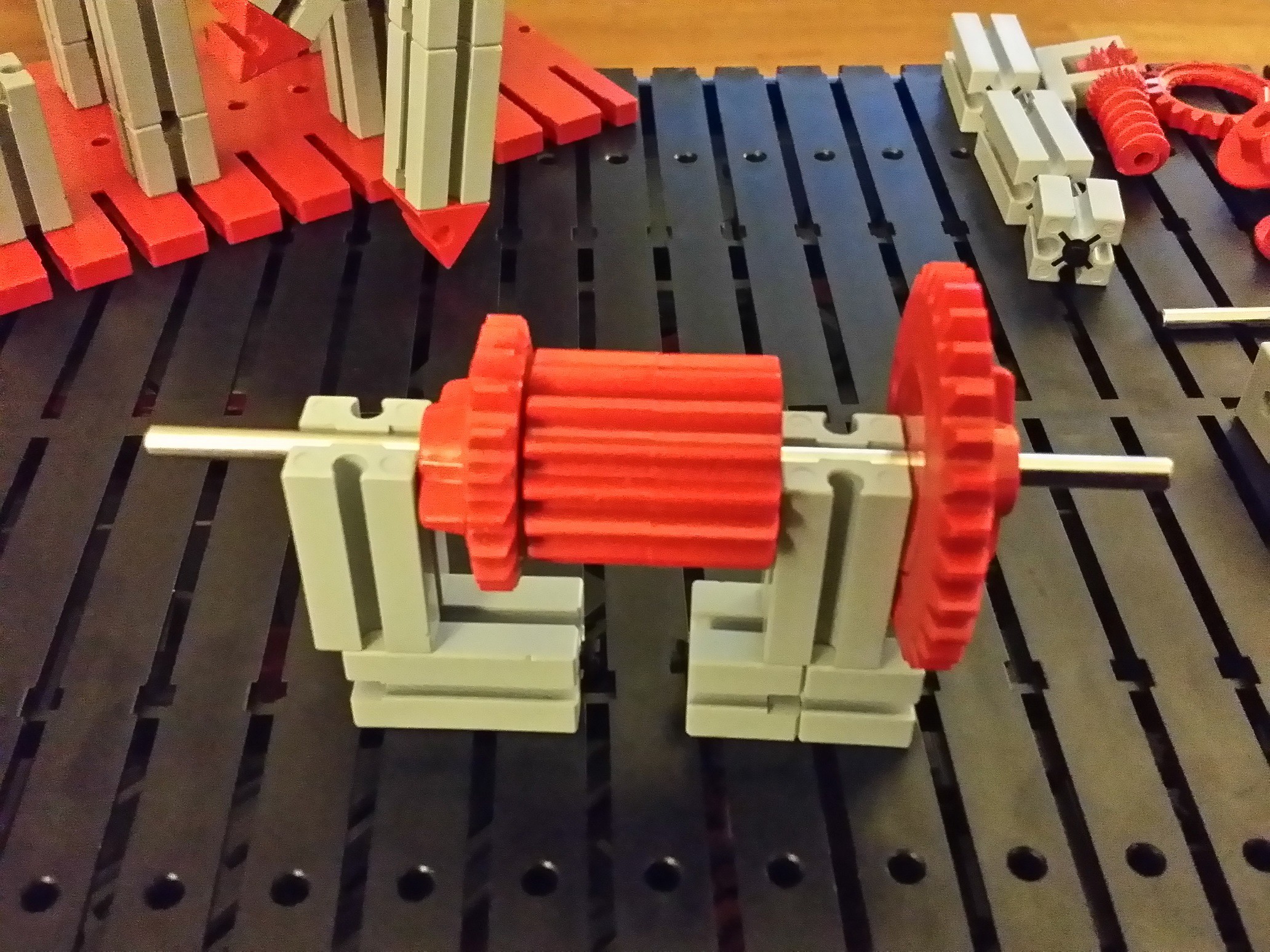
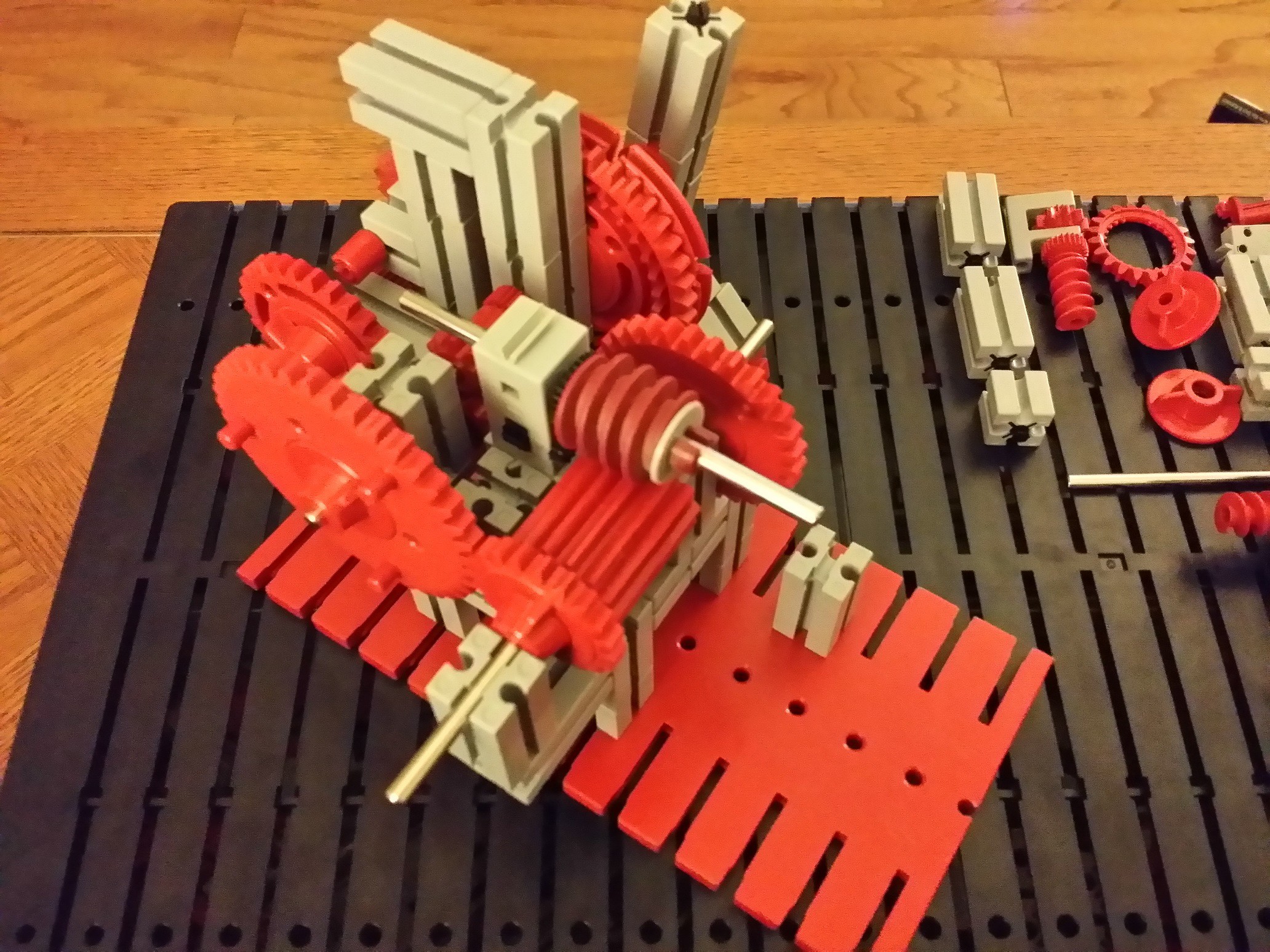
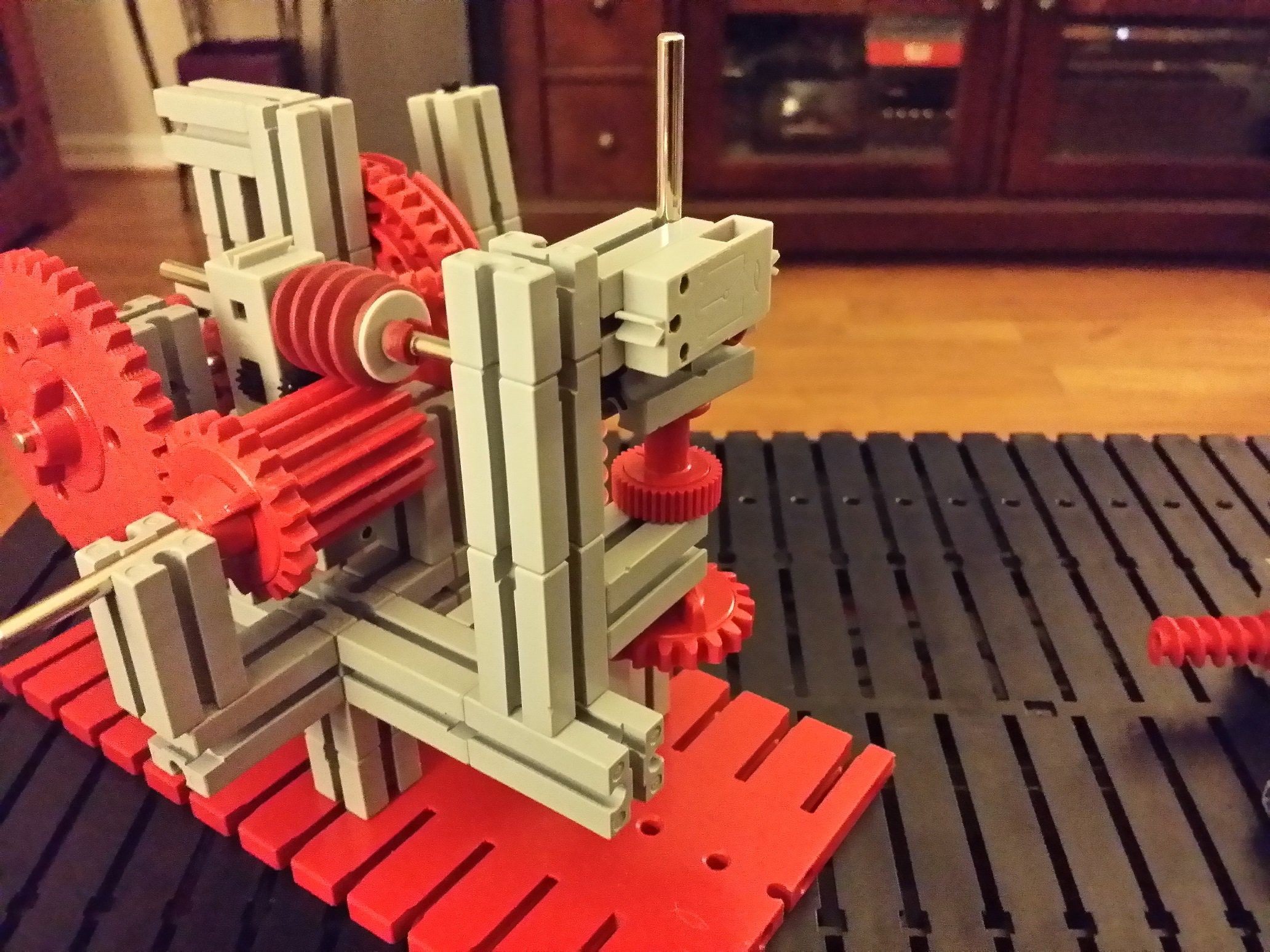
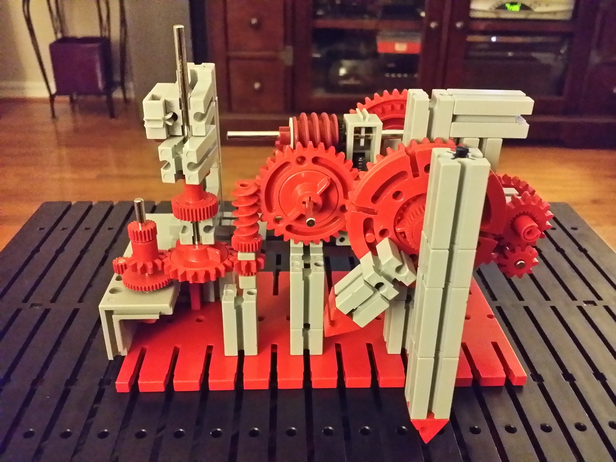
Differential and attached gears.
That weird looking gear near the top of the next picture is a differential. There are three gears inside it: one attached to each axle and one attached to the gear-shaped casing. The casing isn't directly attached to the axles. Normally it's used to transfer the force from a motor (driving the gear-shaped casing) to the axles, and dividing the force over those two axles. If both axles experience the same resistance, they turn equally fast, but if one axle has more resistance (e.g. when a vehicle is going in a curve), the other axle will rotate faster to compensate. if you hold the differential by one axle and rotate the casing, you will see that the other axle rotates twice as fast as the casing. If you hold the casting and rotate one axle, you will see the other axle rotating the opposite direction of the casing.
![]()
![]()
![]()
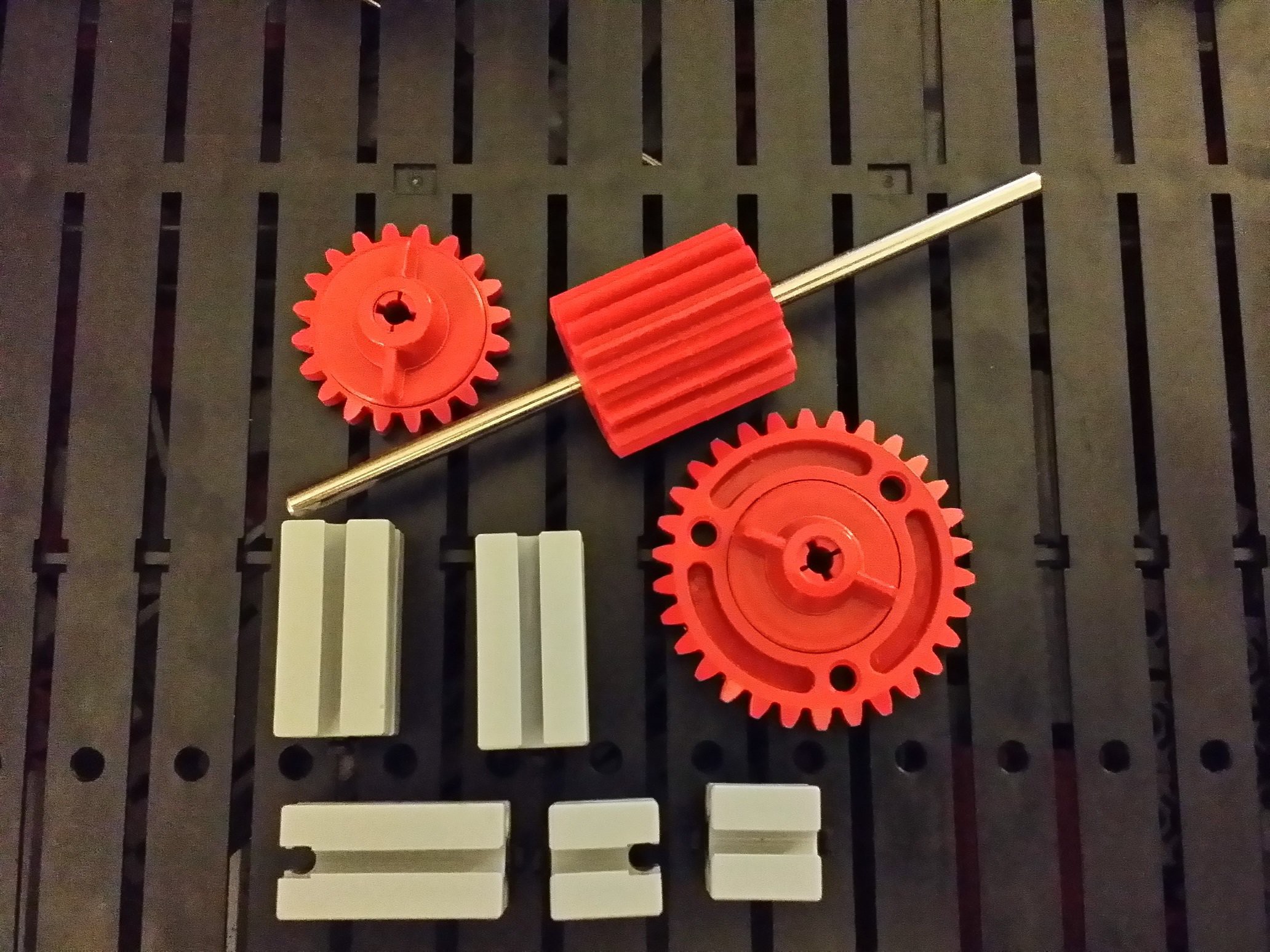
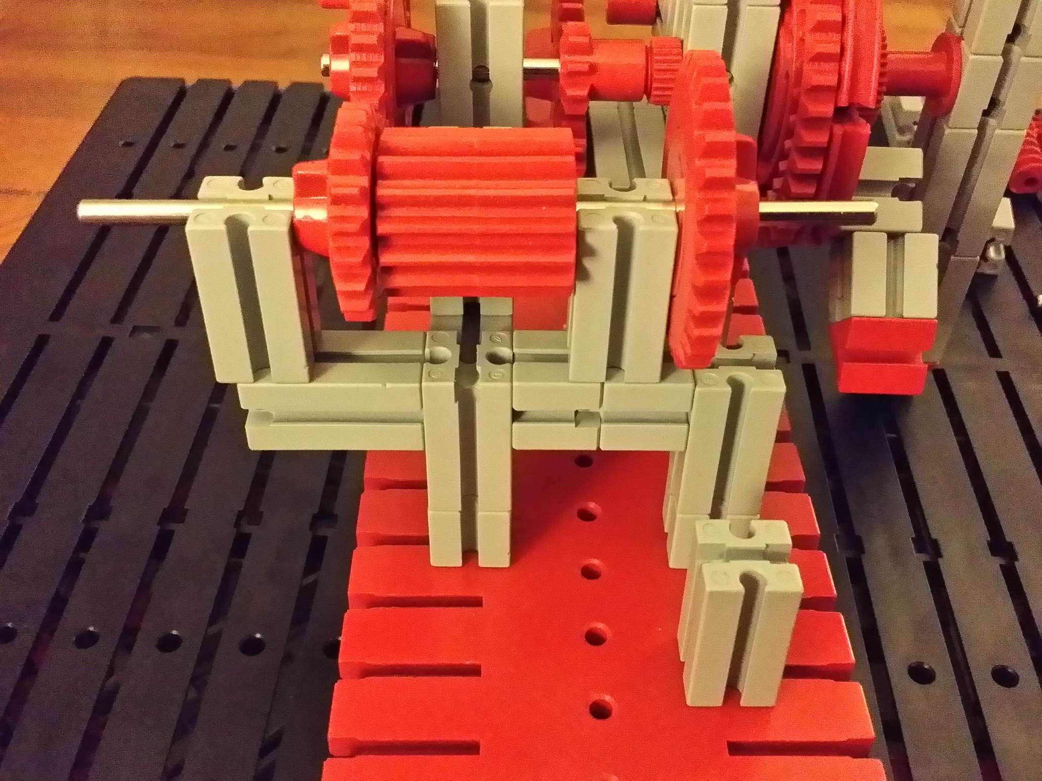
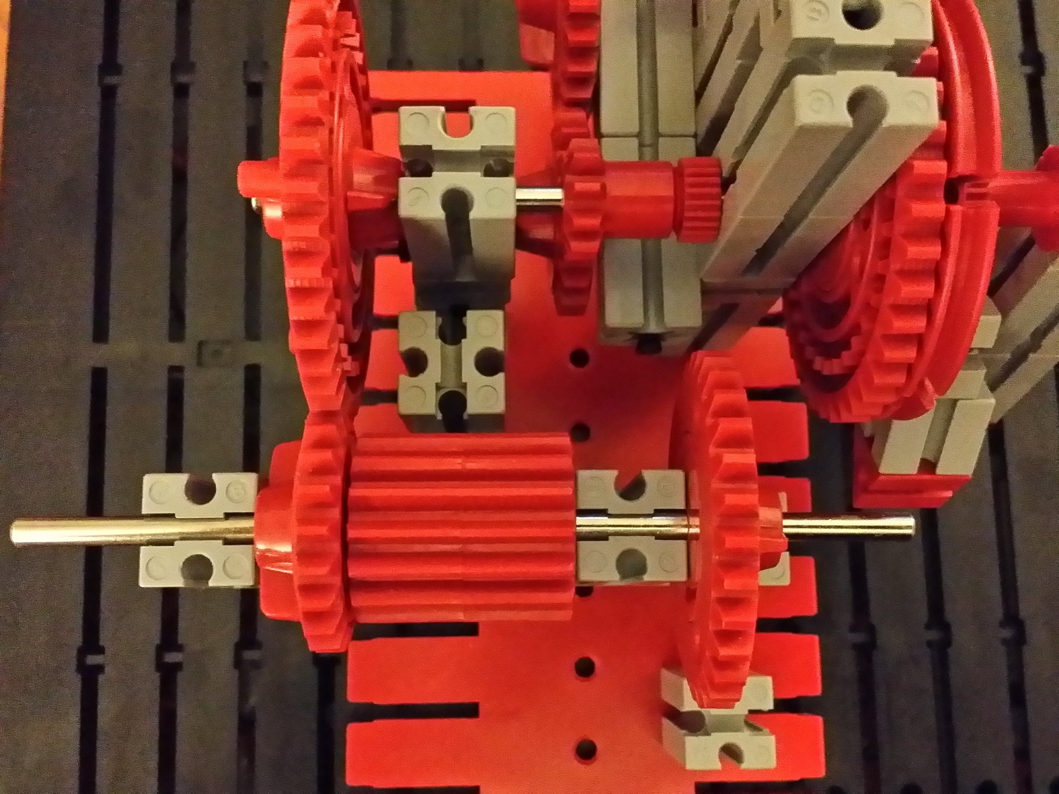
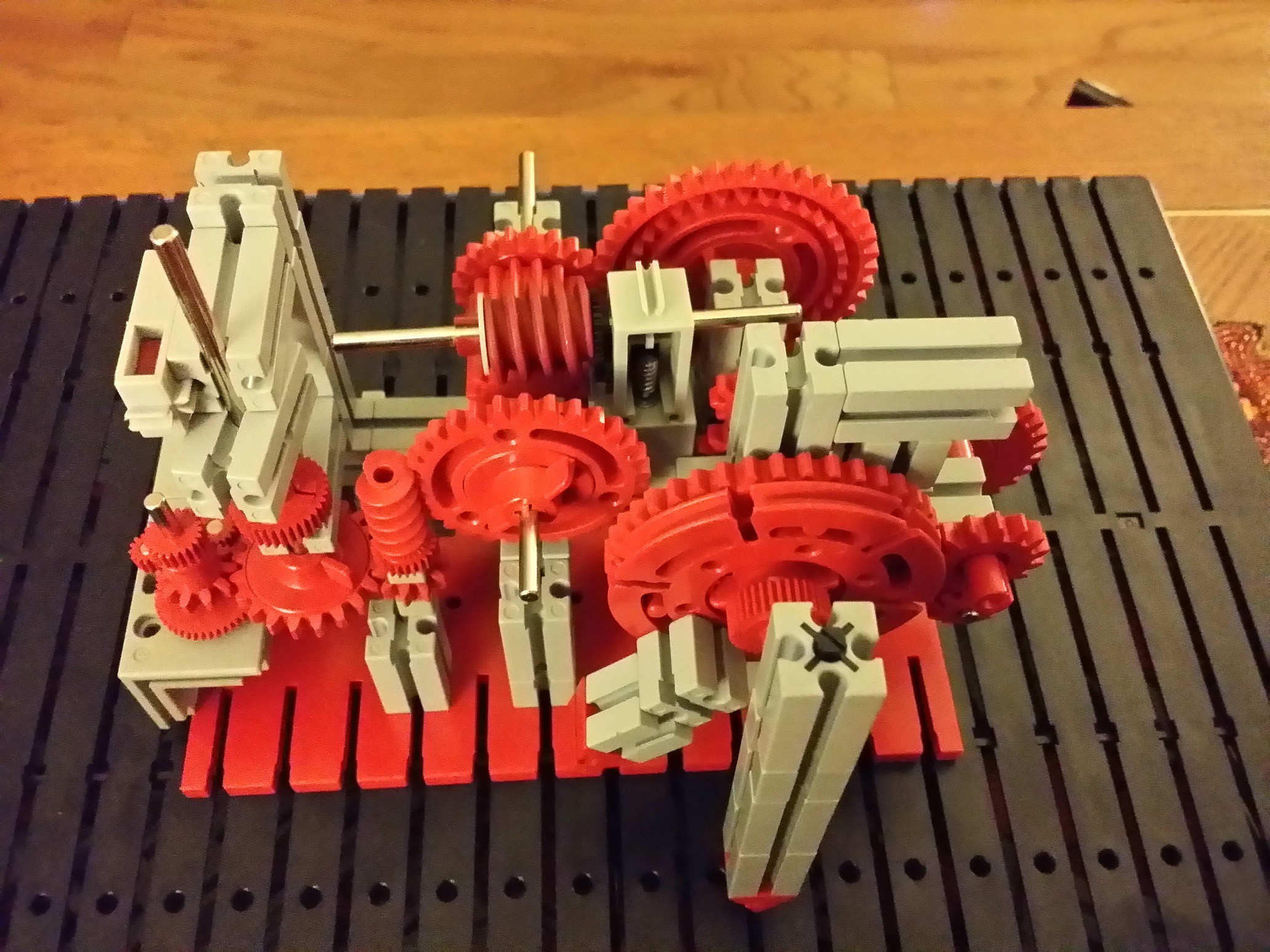
The hubs need to be tightened (just like everywhere else unless mentioned otherwise), but make sure the 20-tooth gear doesn't rub against the casing of the differential.
![]()
![]()
![]()
![]()
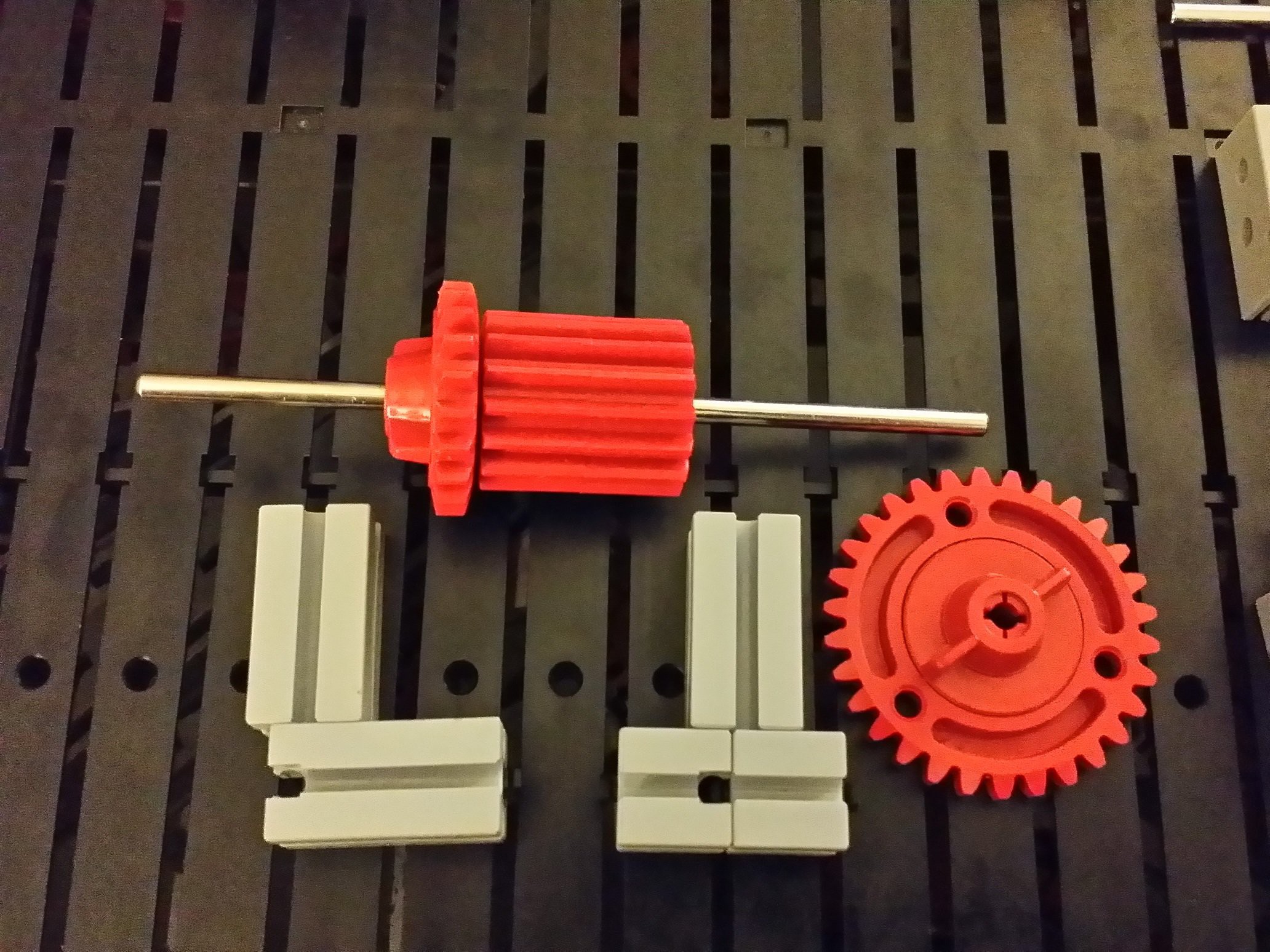
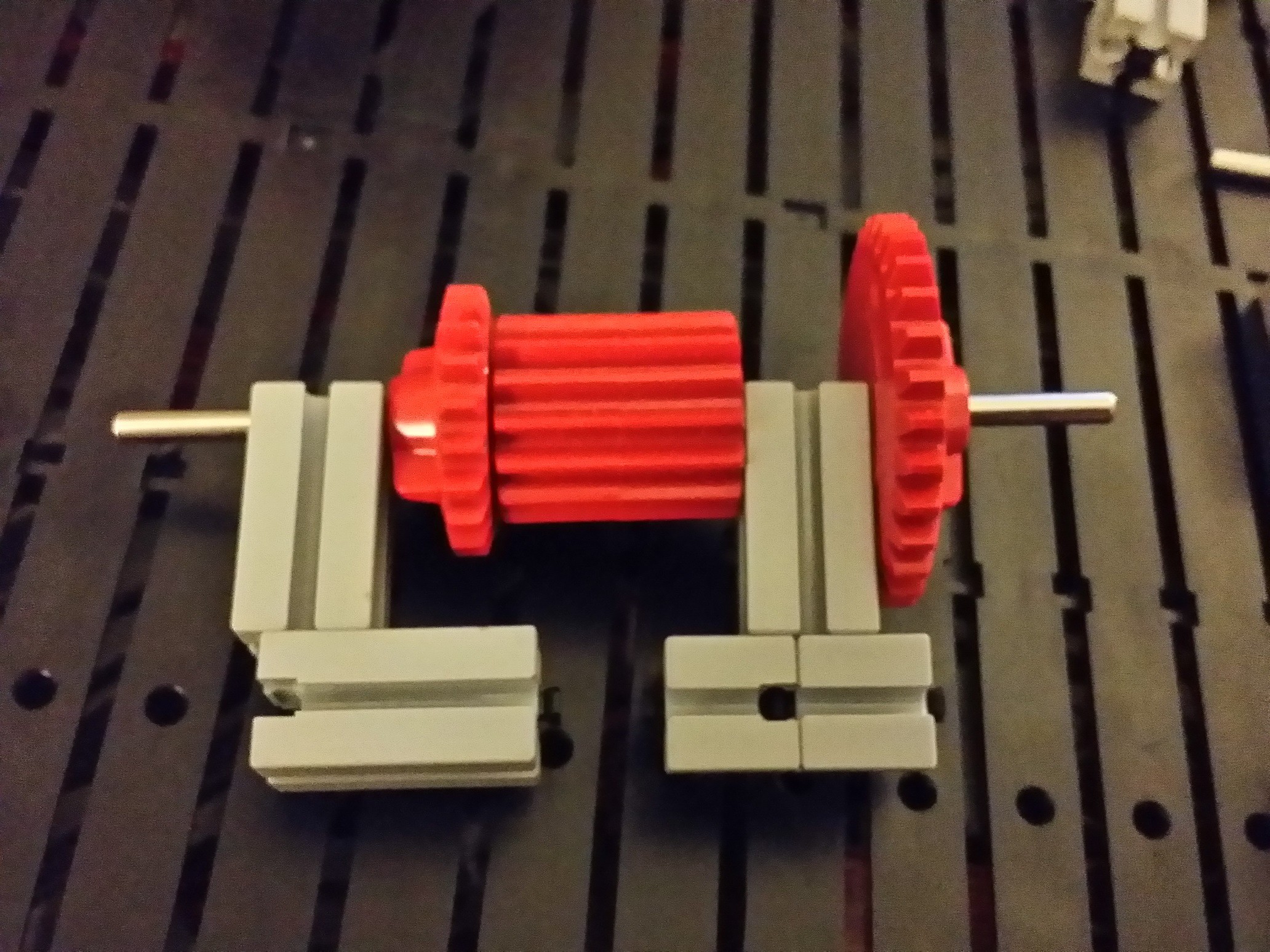
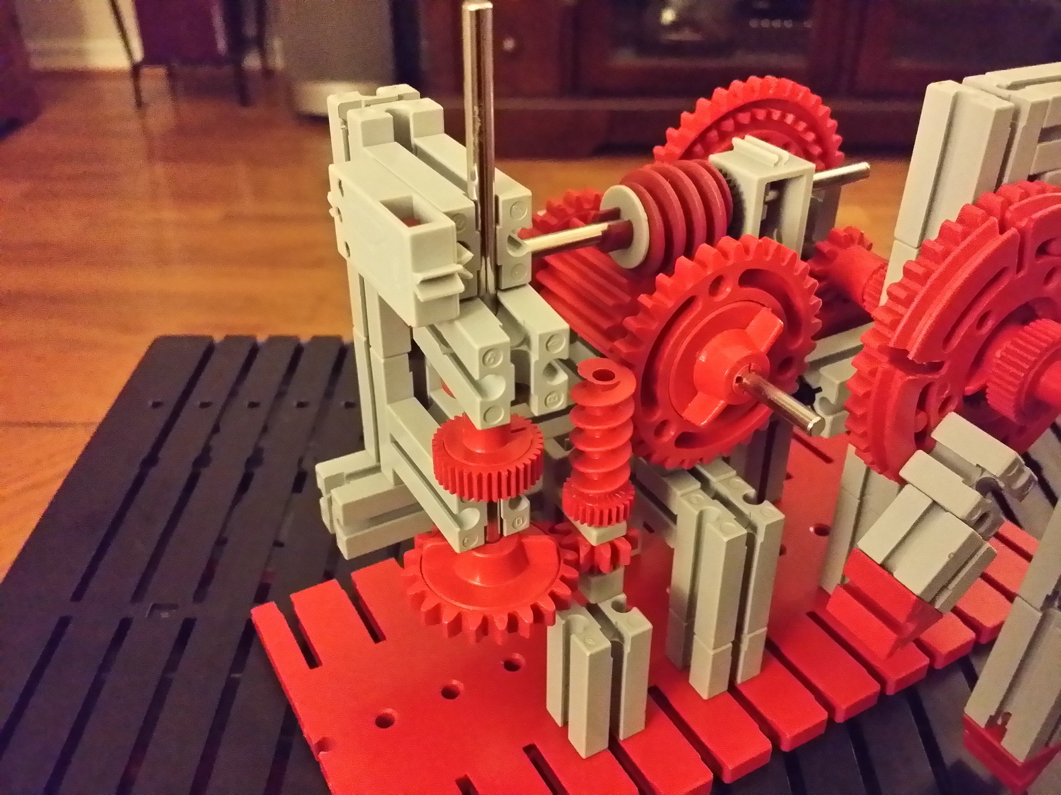
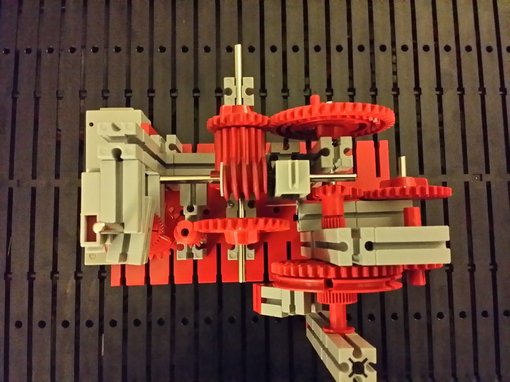
At this point you can hold the differential and turn the 30-tooth gear (bottom right in the picture above) or you can hold the 30-tooth gear and turn the differential, to rotate the minute and hour hands. Check that the friction in the mechanism is minimal.
-
12Step 12
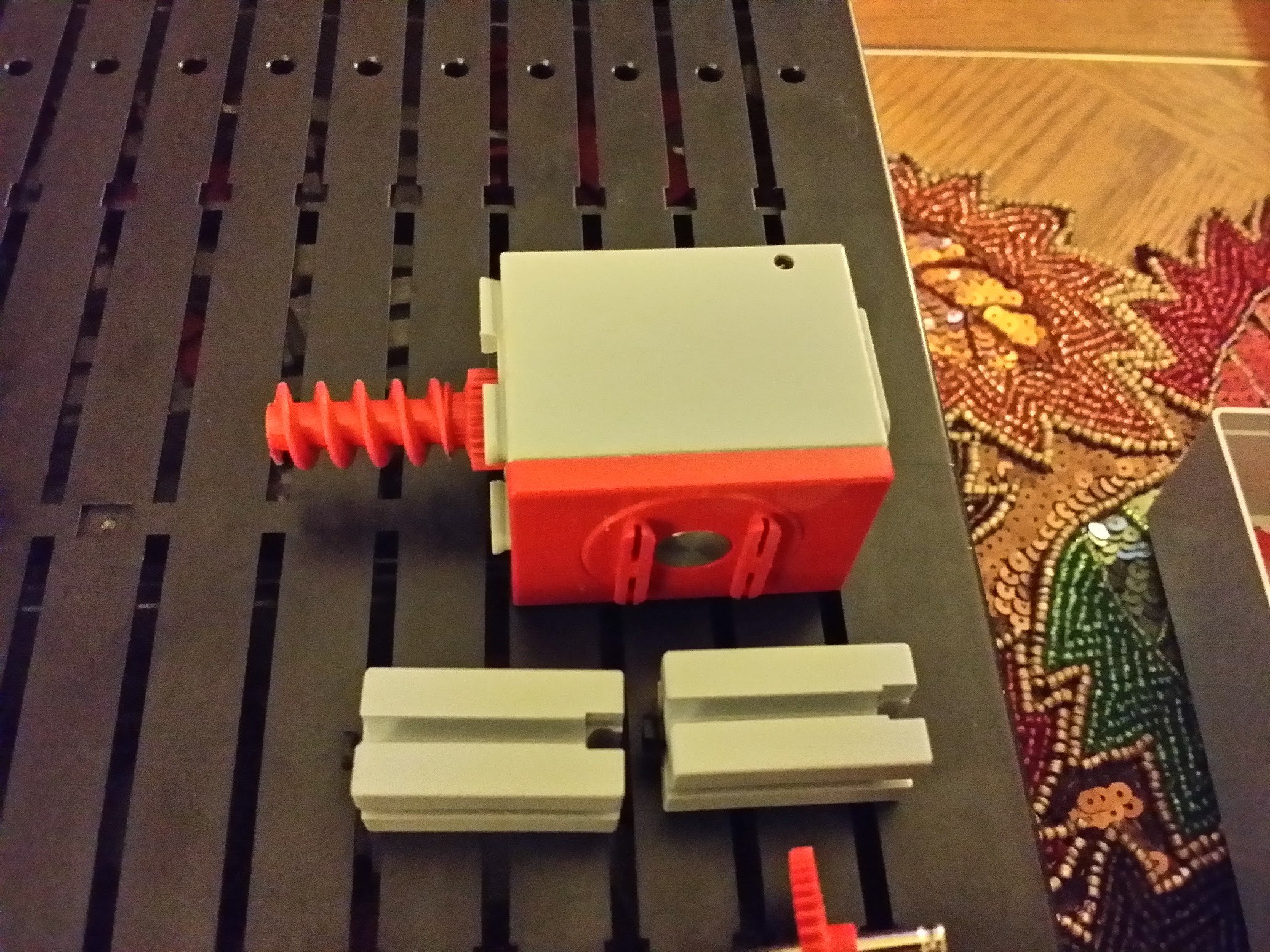
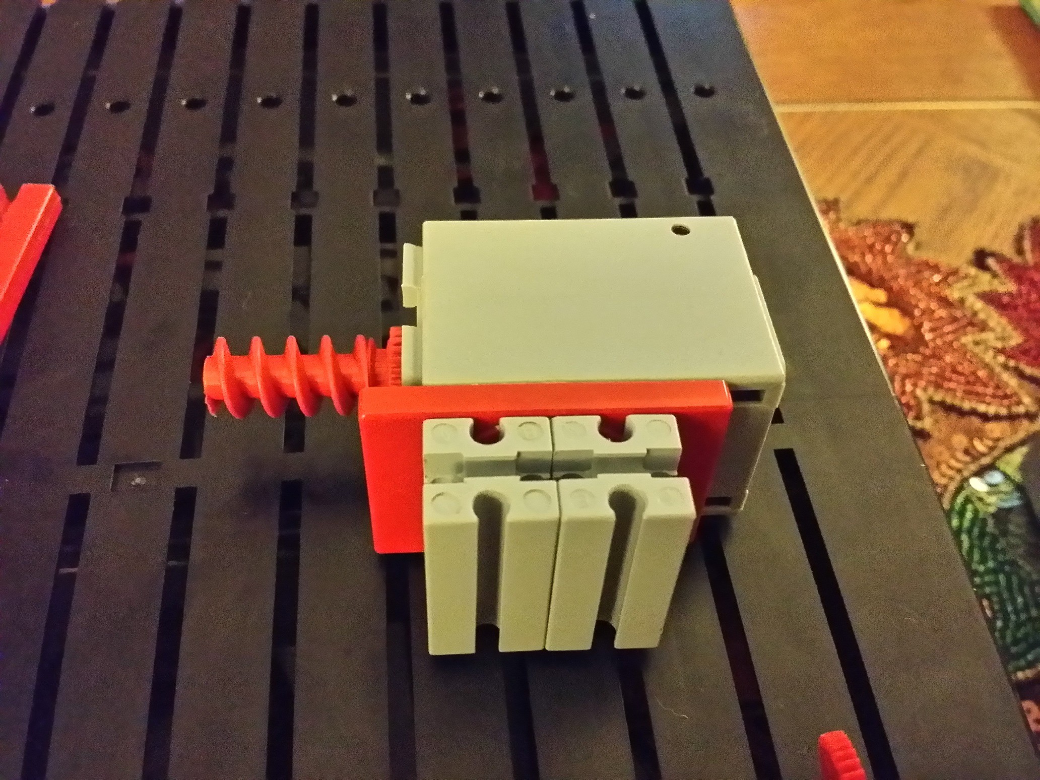
Adjustment motor and transmission. I got these parts from another box. If you don't have these, you can improvise your own. This is for adjusting the time so it's not that critical what parts you use. If you only have one motor, you could just block the casing of the differential with a couple of standard blocks; you would remove those and rotate the differential casing by hand to set the time.
![]()
![]()
![]()
At this time, the differential is blocked by the worm wheel of the mini motor. You can check that whenever you rotate the 30-tooth gear (clockwise), the 20-tooth gear on the other side of the differential rotates in opposite direction, and the minute hand rotates half as fast as the 30-tooth gear. You should still feel minimal friction!
-
13Step 13
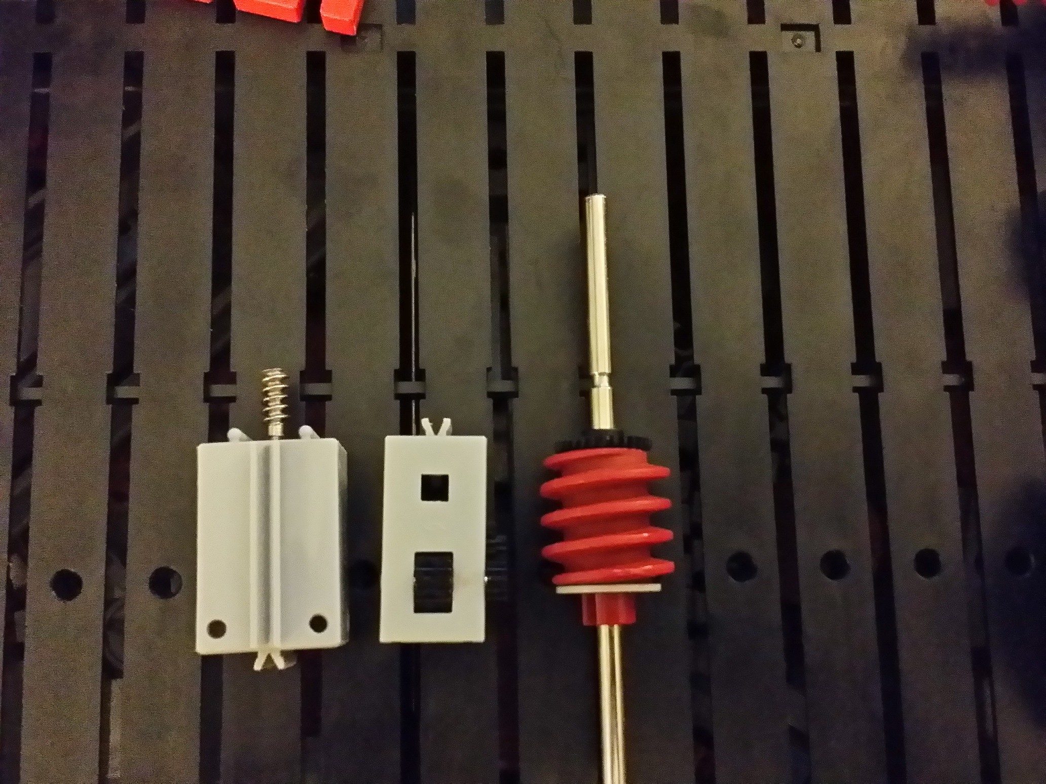
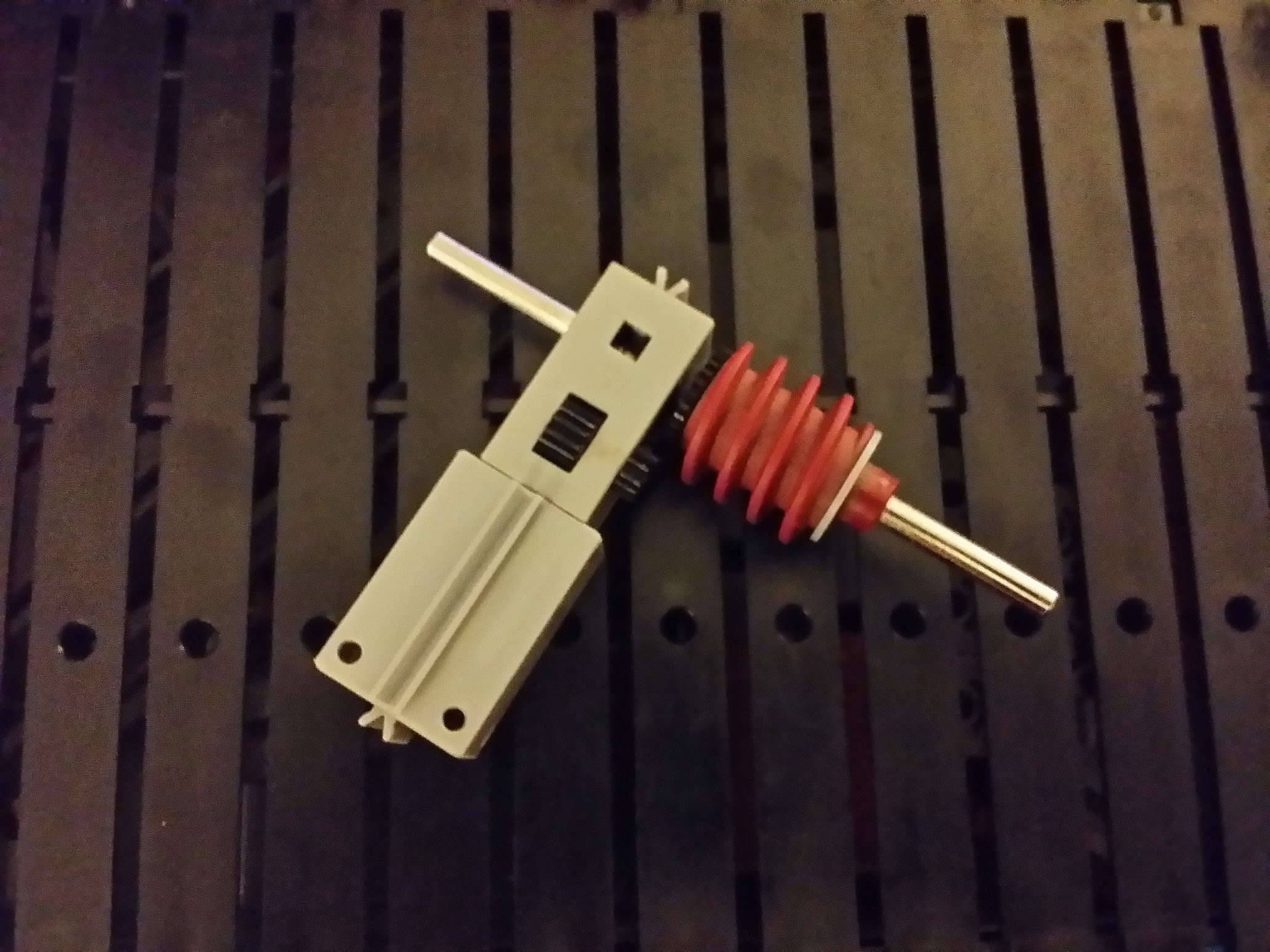
Time keeper worm wheel drive
![]()
![]()
![]()
![]()
![]()
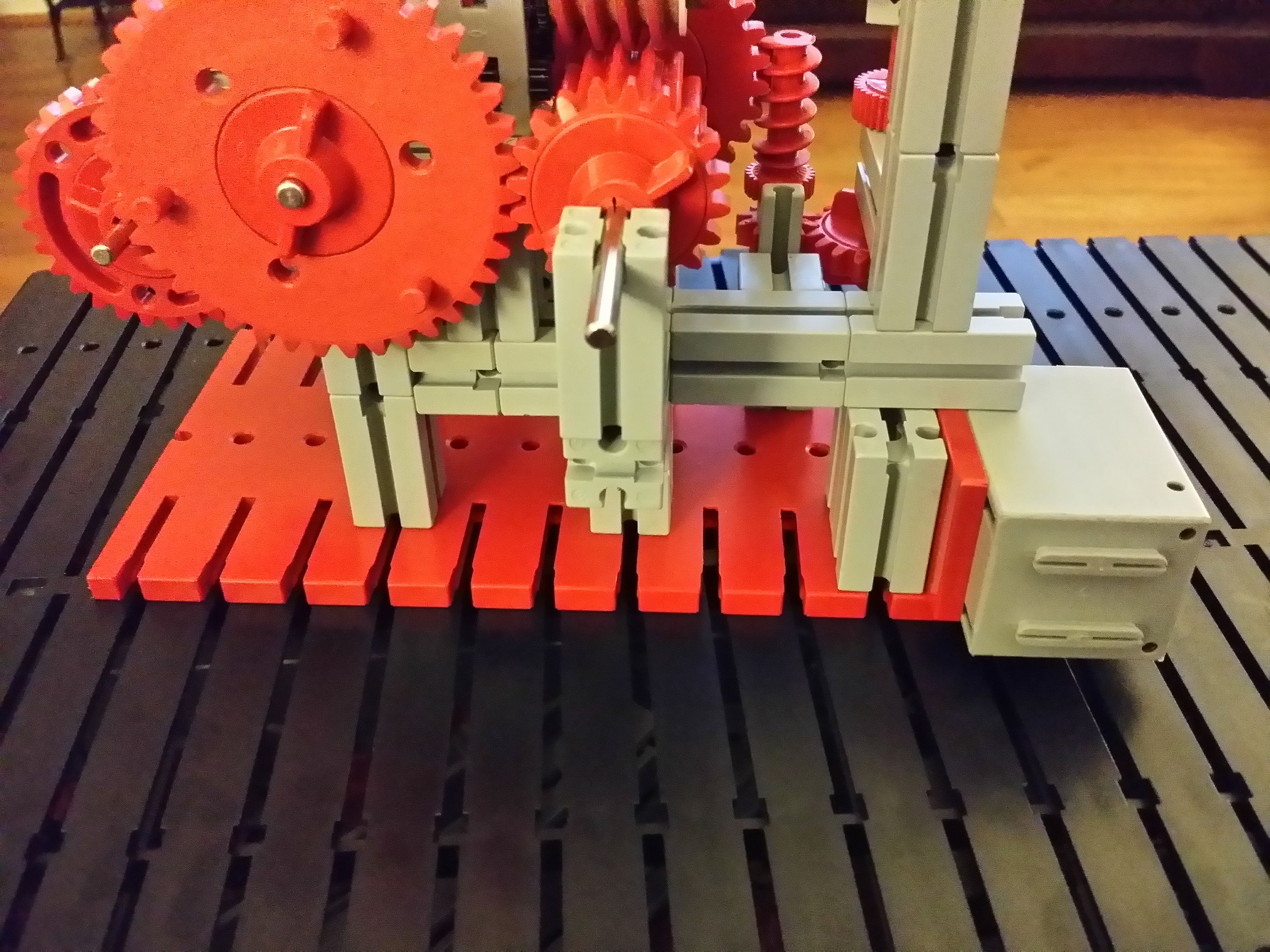
The worm wheel establishes a 30:1 reduction together with the 30-tooth gear. Together with the 40:20 reduction of the gears on the back side of the clock, this makes it so the worm wheel has to rotate exactly 60 times to make the hour hand rotate once.
Note, the work wheel assembly is just "resting" on top of the block that's mounted to the base plate. It's not attached. Can you think of a way to stabilize the mechanism a little?
-
14Step 14
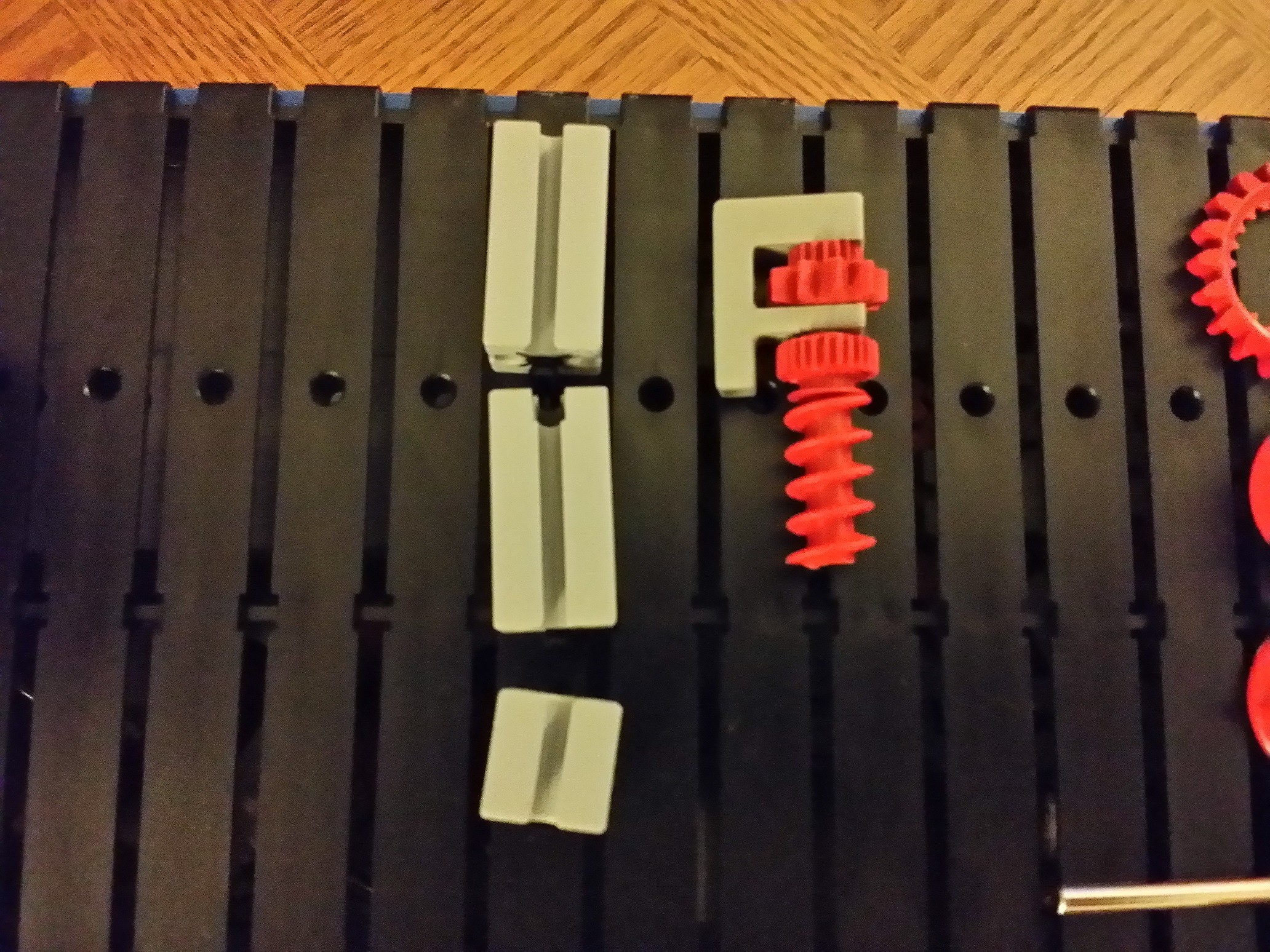
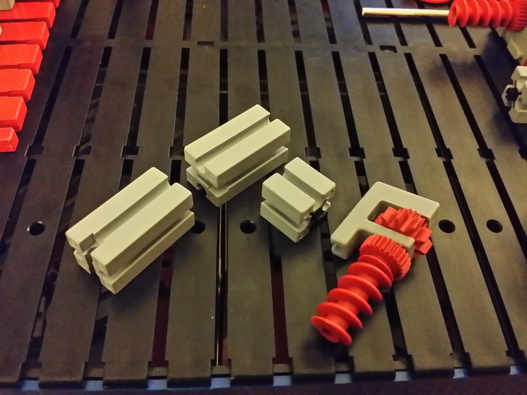
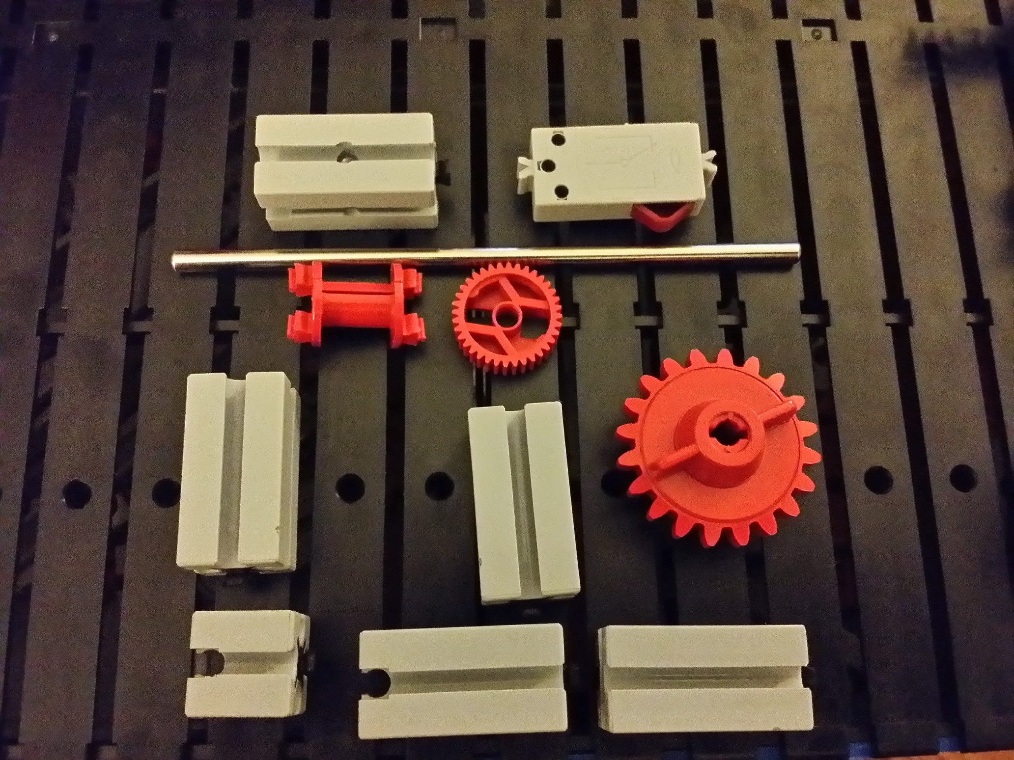
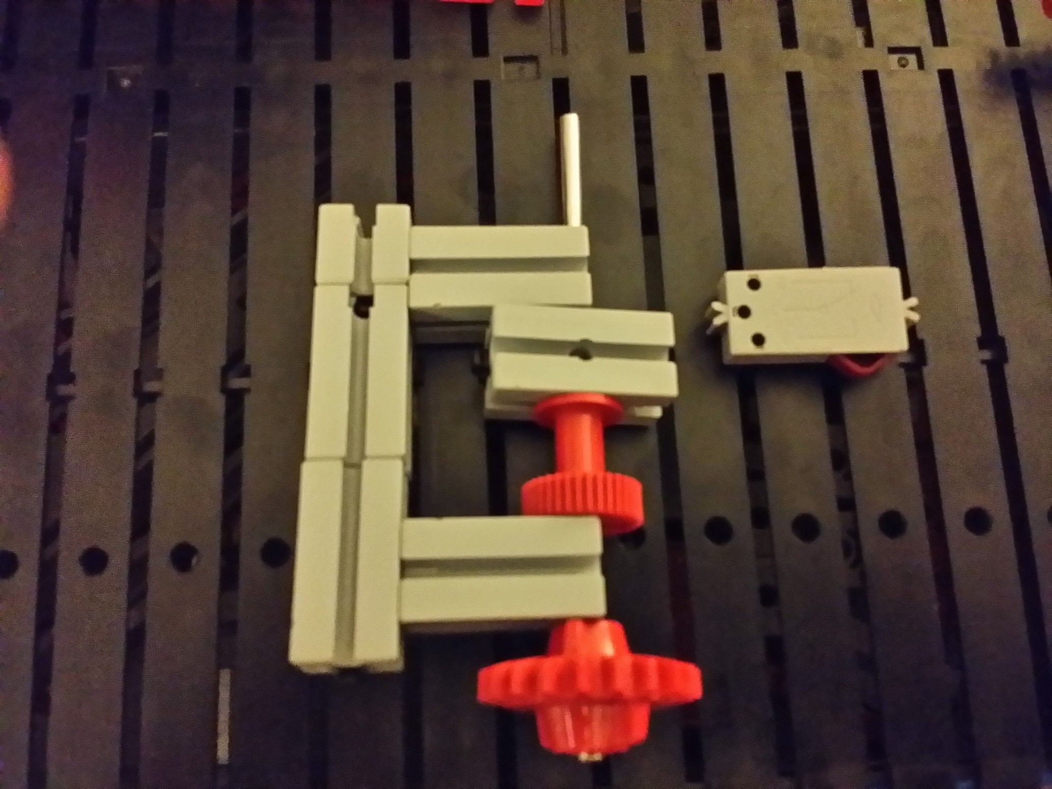
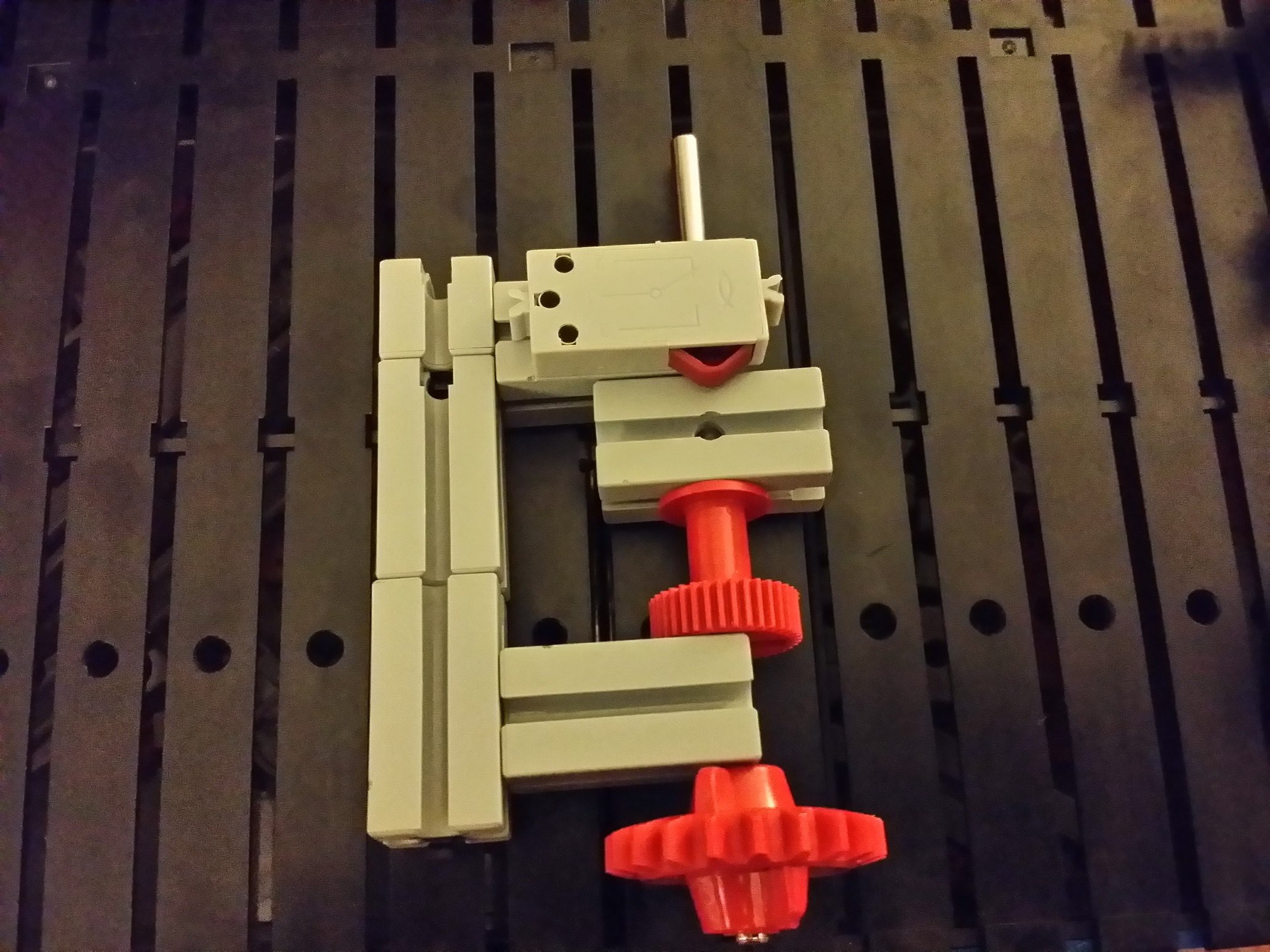
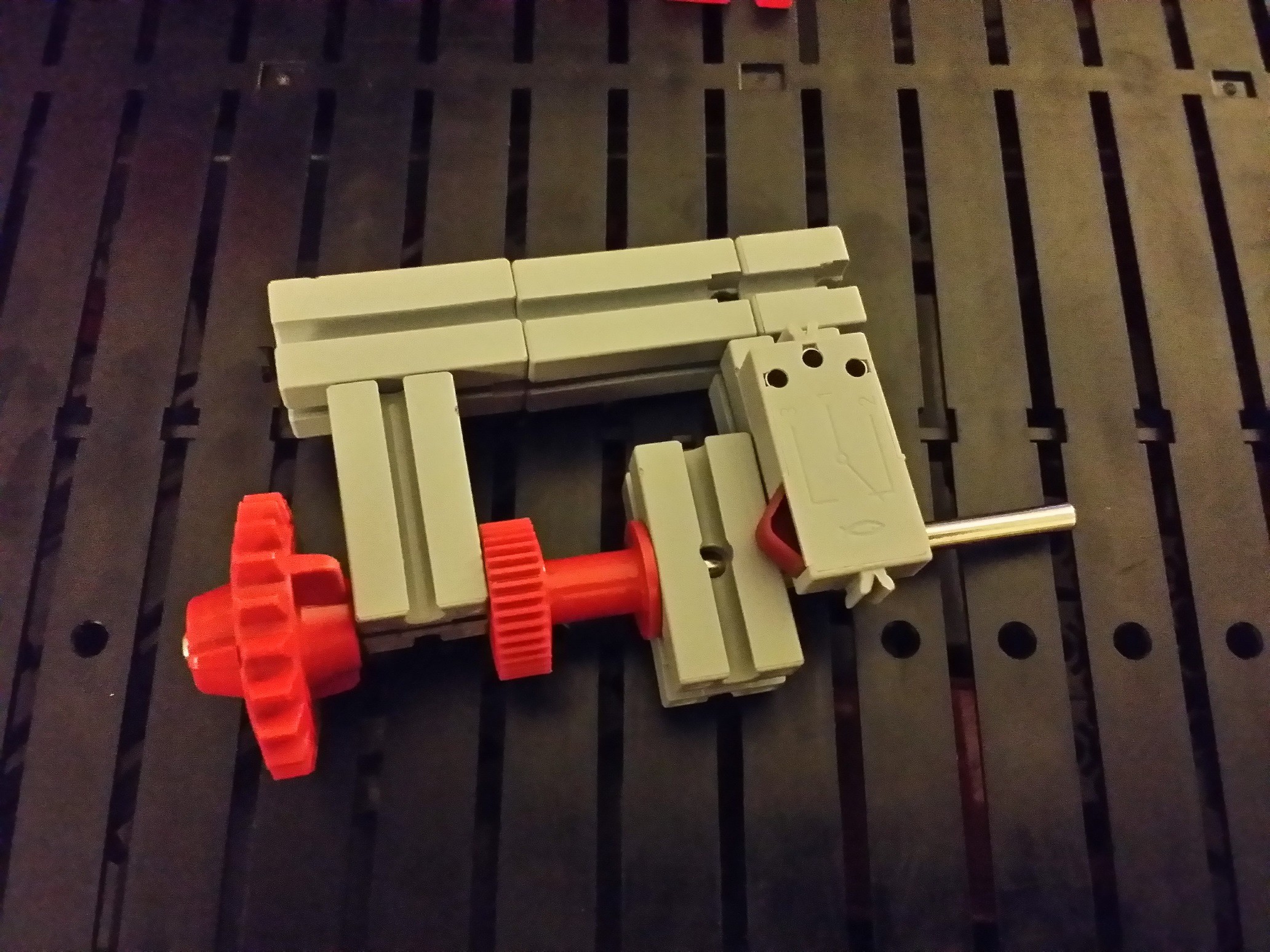
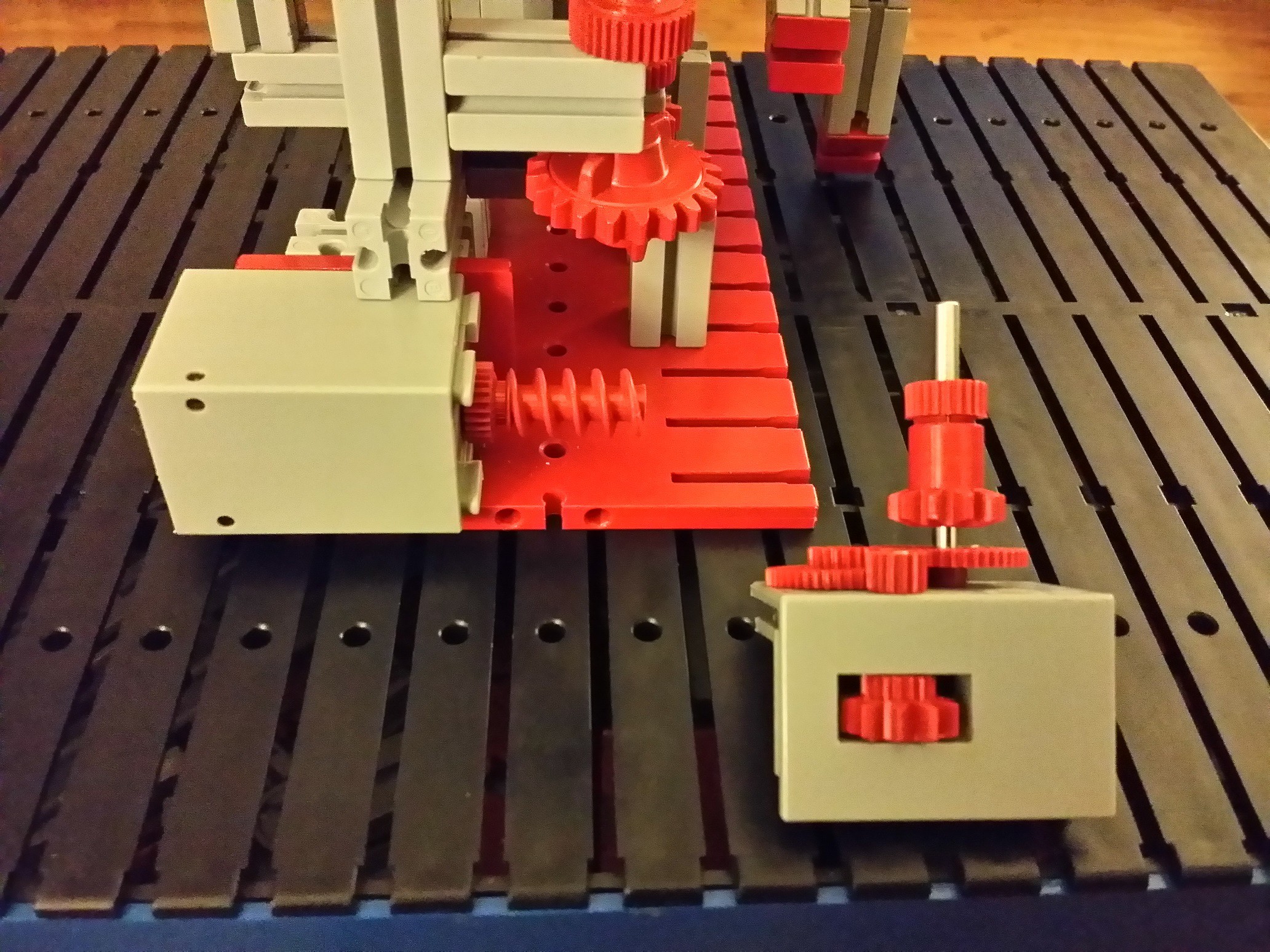
2:1 acceleration and minute sensor.
It's very difficult to make a DC motor run at the exact right speed so that some axle goes around at a certain speed (e.g. once a minute for a second hand in a mechanical clock). There are 86400 seconds in a day, so even if the speed of the motor is off by only 1 percent, the clock will be off by 864 seconds per day. That's more than 14 minutes!
The motor in this clock simply needs to be turned on for a short time every minute. How long, we don't know and we don't care. All that matters is that the minute worm wheel goes around once per minute. The easiest way to do this, once you have an accurate time source, is to attach a sensor that knows when the minute worm wheel goes around exactly once. When the time comes to advance the clock by one minute, the electronics turn the motor on, and wait until the sensor tells it that the worm wheel has gone around.
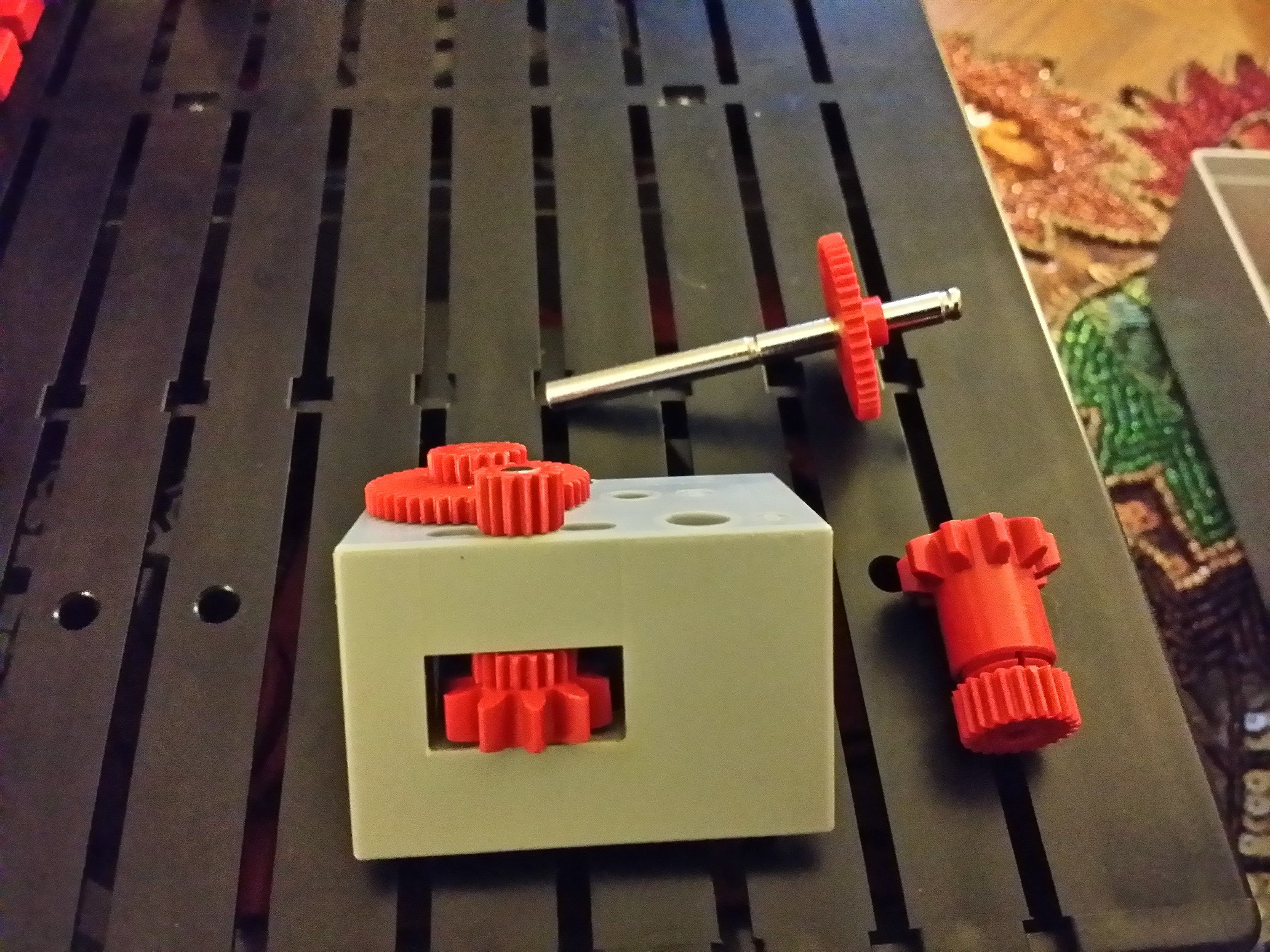
The simplest sensor is a switch but it's too hard to attach a FischerTechnik micro-switch in such a way that it detects that the worm gear has gone around exactly once. It's easier to attach another axle and a gear. When I first built the clock, I started using a 10-tooth gear for a 1:1 gear ratio between the new axle and the worm wheel, but it was too difficult to adjust everything exactly. So instead, I used a 20-tooth gear (1:2 gear ratio) and attached the switch so it gets turned on and off twice per rotation on the new axle, which is exactly once per rotation of the worm wheel.
![]()
![]()
![]()
![]()
![]()
![]()
![]()
-
15Step 15
Time keeping motor
The motor I used came from the Hobby2 box. You can use any motor because the speed is not critical. The important thing to consider here is momentum. If the electronics start the motor to advance the clock by one minute, and then stop the motor again when the sensor switches state, the motor should stop fast enough so that the sensor doesn't change state again before the mechanism comes to a complete stop.
![]()
![]()
![]()
![]()
![]()
![]()
-
16Step 16
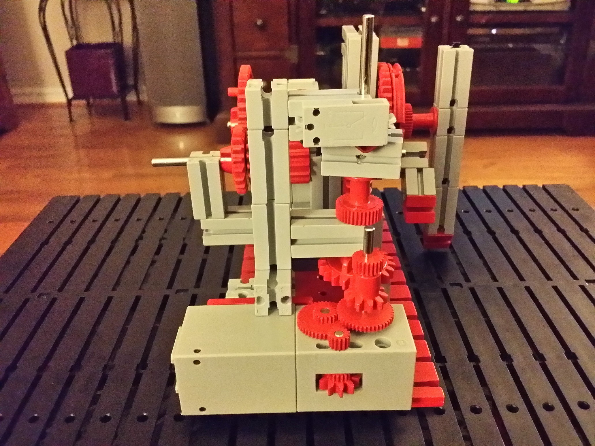
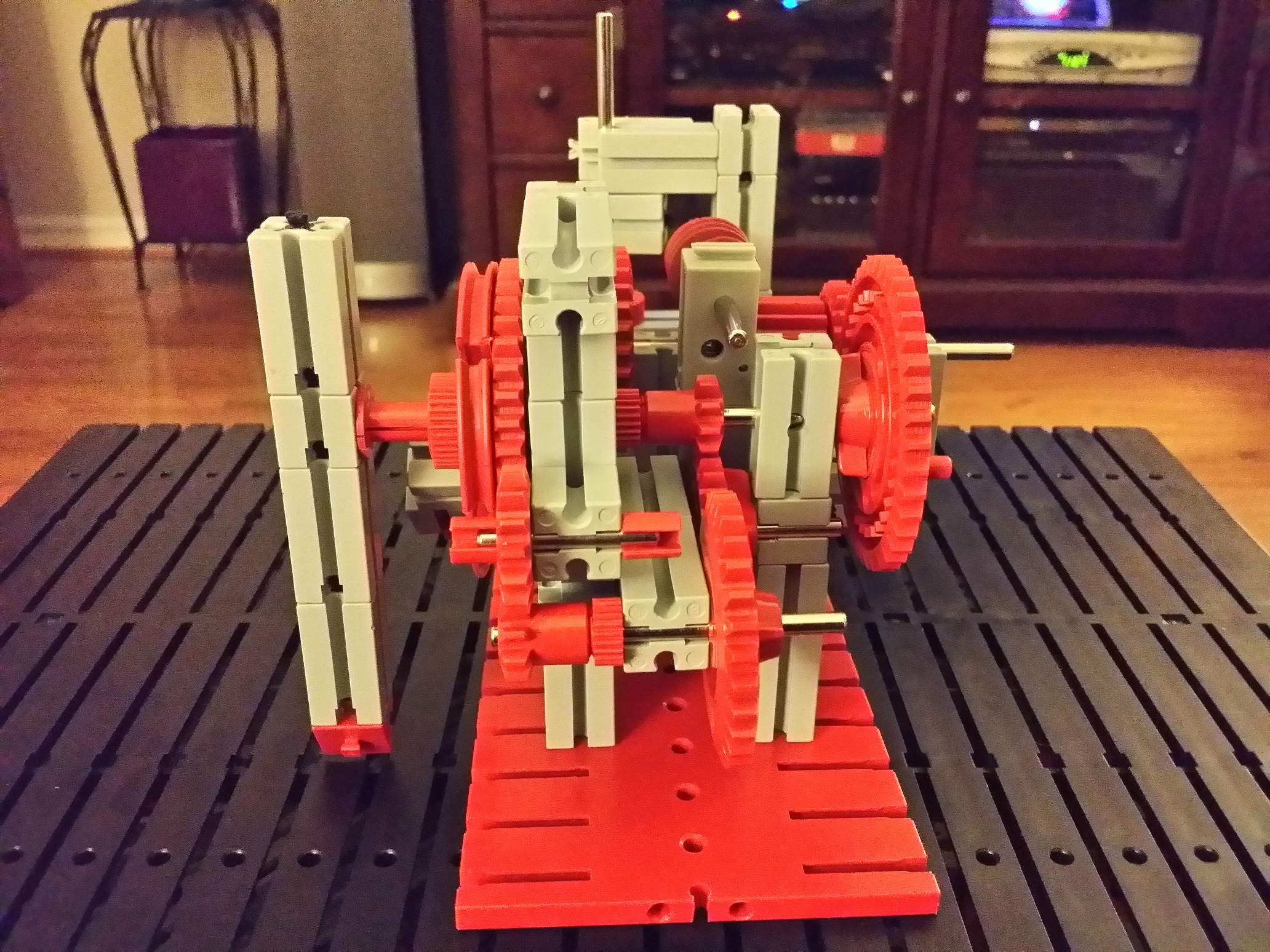
The mechanism is now ready!
Admire your work, and think of how you could use this to show accurate time. Unfortunately it's not possible to use FischerTechnik parts (only) to derive an accurate once-a-minute pulse from the mains frequency or from another source. But a microcontroller such as an Arduino will do the trick. And with some extra mechanics and sensors, it will even be possible for the clock to set its own time, based on e.g. a GPS receiver. I hope to add those to the project soon.
![]()
![]()
![]()
![]()
Discussions
Become a Hackaday.io Member
Create an account to leave a comment. Already have an account? Log In.