Jac Goudsmit
-
Keeping Time, part 2
11/19/2015 at 08:06 • 0 commentsAs I mentioned in my last log, the FischerTechnik clock presented in this project can't run without some electronics. I already explained that the clock can run with just a pulse generator that advances the hands by a minute, once a minute. But I wanted to go a little further. I wanted the clock to set itself to the correct time, and stay accurate as long as it was running.
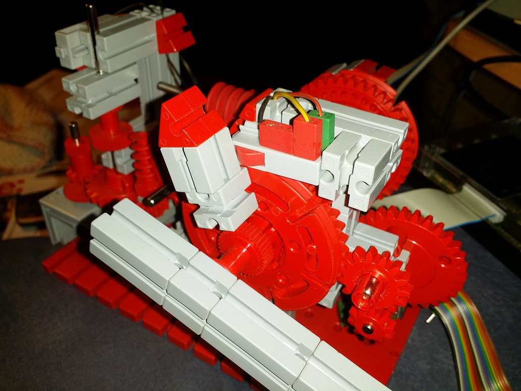
I added two switches to the clock, to be used as sensors. One switch detects when the hour hand is in the "12 o'clock" position:
![]()
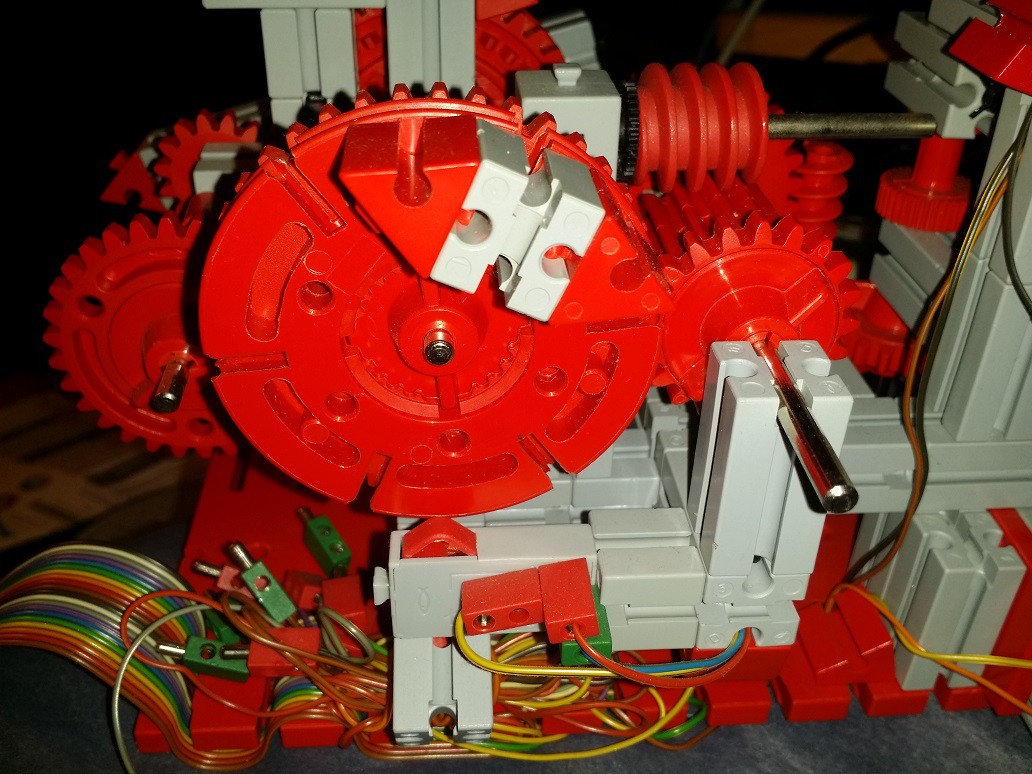
The other switch detects when the minute hand is at the top of the hour (0 minutes). It's on the back side of the clock.
![]()
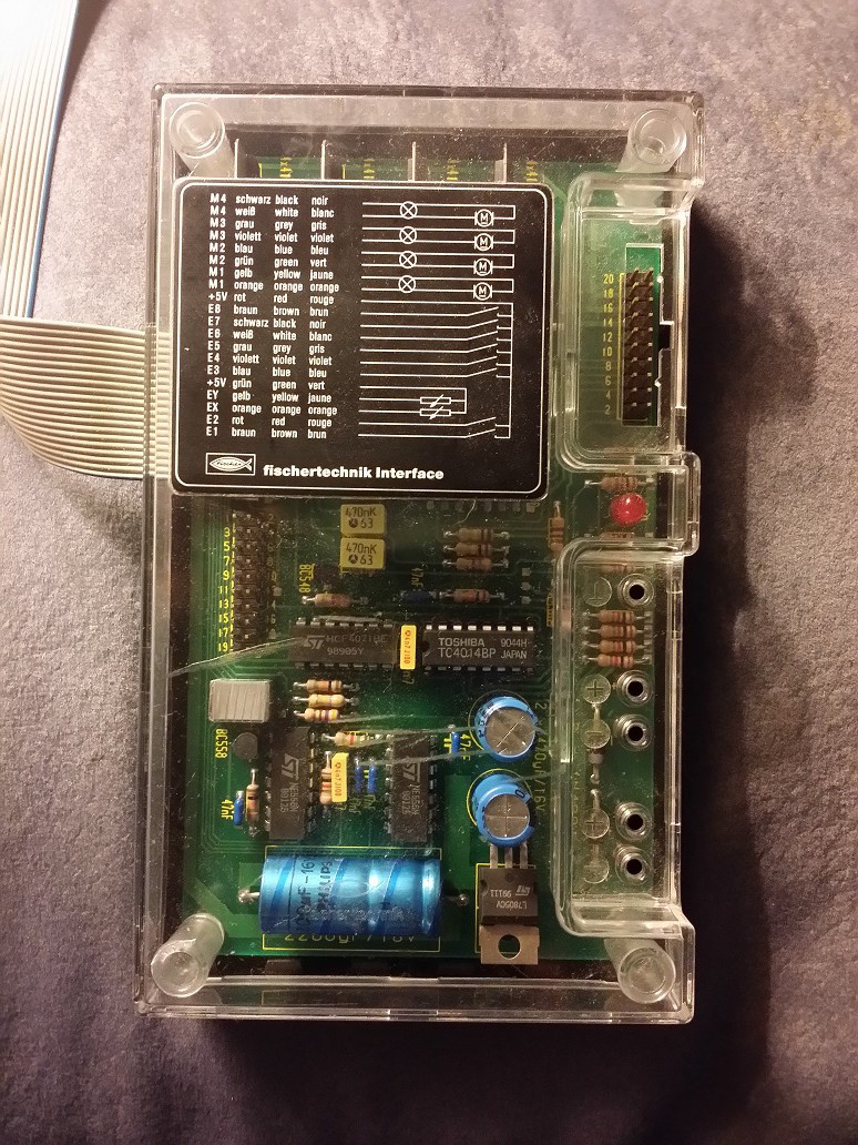
The switches and the two motors are connected to the FischerTechnik Computing interface (type 30520) from 1987 or so, that I got from eBay (the mini-motor that I use for adjusting the clock, and the worm wheel and the switches are also from the FischerTechnik Computing box). The "rainbow" ribbon cable in the photo above plugs into the header at the top right of the photo below. There's a sticker suggesting how to connect light bulbs, motors, switches and variable resistors to the interface. The loose plugs in the picture above are unused inputs and outputs; I don't use the analog inputs for this project so there are no variable resistors and no light bulbs either.
![The "30520" interface]()
The white ribbon cable that's attached to the interface has a 20 pin connector on the end, that was originally plugged into a small circuit board that would plug into a computer. Various different computers were supported, each with their own plug-in board. My Computing box had a plug-in board with a DB-25 connector that would connect to the parallel printer port of an IBM PC, Amiga or Atari ST. The software to control the interface was not included with my box. Not that it matters, because it was written for MS-DOS and wouldn't have worked on modern versions of Windows (or any other modern operating system for that matter, except FreeDOS perhaps).
The interface is very simple: it has 8 digital inputs, 2 analog inputs, and 8 digital outputs. The computer has to do all the work. The inputs and outputs are controlled by parallel-serial and serial-parallel converters and the computer has to clock the data in and out one bit at a time, by turning individual pins on and off on the interface cable (for more information, click here). That's fine for an old computer, but for modern computers, this is a difficult thing to do, mainly because operating systems are designed to keep software away from hardware: only device drivers can bitbang ports. But a microcontroller such as the Arduino is perfect for the job.
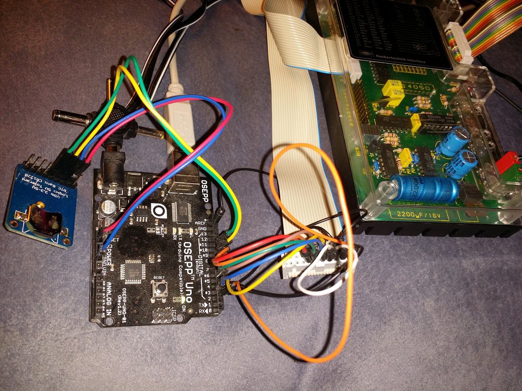
So I connected the interface to an Arduino (I know, shame on me for getting a fake one, but at the time that I bought it, Fry's Electronics didn't sell the official Arduino) by plugging breadboard patch wires into the interface plug and the Arduino headers. For more details about how it was wired up, see the Fishduino.h module in my Github. I also connected an Adafruit Ultimate GPS Breakout to keep track of time.
![]()
The 30520 interface is no longer supported by any FischerTechnik software, but thanks to its simplicity, it was reverse-engineered a long time ago. This made it easy for me to create an Arduino library called Fishduino to control the interface. I even wrote a sample sketch that emulates the "Intelligent" interface (30420) which has a serial interface, and is still supported by current versions of the FischerTechnik software. But this project is a standalone device, so it doesn't use the 30420 emulator sketch, nor does it need a connection to a PC (except for debugging).
![]()
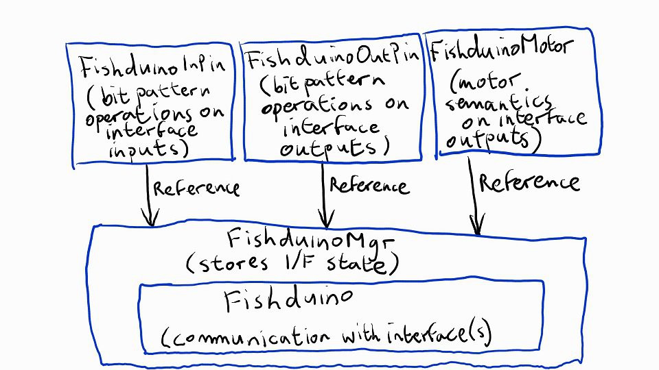
The architecture of the Fishduino library is basically as follows:
- The Fishduino class takes care of the communication with the interface, or interfaces: The hardware is designed so that multiple interfaces can be cascaded, and this is supported by the class.
- The FishduinoMgr class is a subclass of FishDuino so it has the same functions as Fishduino, but in addition, it keeps track of the state of the inputs and outputs. That way, the main program doesn't have to do this.
- The FishduinoInPin class represents, and performs operations on one or more bits of the stored input state of a FishduinoMgr.
- The FishduinoOutPin class represents and performs operations on one or more bits of the stored output state FishduinoMgr.
- The FishduinoMotor class also represents digital outputs like the FishduinoOutPin class, but uses motor semantics (i.e. "clockwise", "anticlockwise" and "stop" instead of "on" or "off") to control two adjacent output pins at the same time.
The input pin class, output pin class and motor class simply change bits in the internal state of the FishduinoMgr. To actually read the inputs and write the outputs, the program still has to call the appropriate Update function in the FishduinoMgr class.
As usual, pins 0 and 1 are used for the serial connection with the PC. This connection is not needed during normal operation, only for debugging and downloading the program of course.
Pins 2 to 8 are used by the FischerTechnik interface (see the Fishduino.h source file for exact pin assignments).
Pins 9 and 10 are used by the GPS module.
![]()
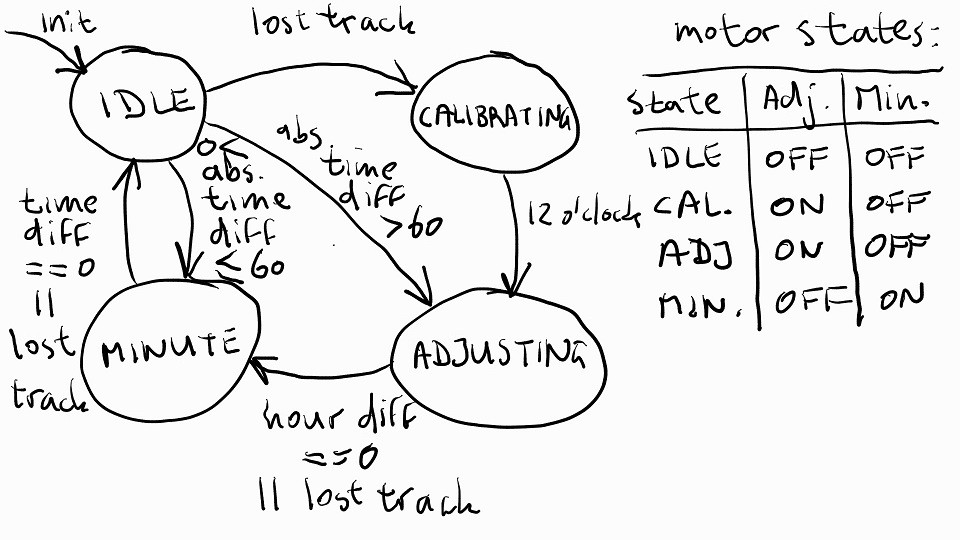
The clock program has four states:
- Idle: when both motors are off and the microcontroller is waiting for a change to the time, received from the GPS module.
- Calibrating: when the program has lost track of where the hands are, and needs to run the adjustment motor to find the 12 o'clock position
- Adjusting: when the program runs the adjustment motor to adjust the clock time to the hour that's nearest the actual time
- Minute: when the program runs the minute motor to adjust the clock to the exact actual time.
The clock program declares a FishduinoMgr instance to represent the FischerTechnik interface, and it declares variables to represent the two motors and three switch sensors:
<span class="hljs-comment">// FischerTechnik Clock hardware</span>
FishduinoMgr        fishduino;
<span class="hljs-function">FishduinoMotor      <span class="hljs-title">motor_min</span><span class="hljs-params">( fishduino, 0, FishduinoMotor::M1)</span></span>;
<span class="hljs-function">FishduinoMotor      <span class="hljs-title">motor_adj</span><span class="hljs-params">( fishduino, 0, FishduinoMotor::M2)</span></span>;
<span class="hljs-function">FishduinoInPin      <span class="hljs-title">sensor_m</span><span class="hljs-params">(  fishduino, 0, FishduinoInPin::I1)</span></span>; <span class="hljs-comment">// Cycles once/minute</span>
<span class="hljs-function">FishduinoInPin      <span class="hljs-title">sensor_h</span><span class="hljs-params">(  fishduino, 0, FishduinoInPin::I3)</span></span>; <span class="hljs-comment">// Cycles once/hour</span>
<span class="hljs-function">FishduinoInPin      <span class="hljs-title">sensor_h12</span><span class="hljs-params">(fishduino, 0, FishduinoInPin::I2)</span></span>; <span class="hljs-comment">// Cycles once/12 hours</span>
As you can see, the various classes in the Fishduino library make it easy to recognize that I connected the minute motor to the M1 outputs (see also the sticker on the interface in the photo above). The adjustment motor is on the M2 outputs. The switches are connected to i1, i2 and i3.
The minute hand is adjusted in such a way that Sensor_h goes from the ON state to the OFF state at the exact point when the minute hand goes from the :59 position to the :00 position. The position where the switch changes from OFF to ON is not important.For the 12 o'clock sensor, it doesn't really matter at which exact position it turns on and off. The only requirement is that when the minute hand changes from :59 to :00 (and the hour sensor switch turns OFF), the 12 o'clock sensor is ON at 12 o'clock and OFF at any other hour.
<span class="hljs-comment">// Actual time (that we're supposed to display)</span>
<span class="hljs-keyword">byte</span>                actual_hour = <span class="hljs-number">255</span>;  <span class="hljs-comment">// Hours mod 12 (i.e. 0..11); unknown=255</span>
<span class="hljs-keyword">byte</span>                actual_min  = <span class="hljs-number">255</span>;  <span class="hljs-comment">// Minutes; unknown=255</span>
<span class="hljs-comment">// Current time on the clock</span>
<span class="hljs-keyword">byte</span>                clock_hour  = <span class="hljs-number">255</span>;  <span class="hljs-comment">// Hours mod 12; unknown=255</span>
<span class="hljs-keyword">byte</span>                clock_min   = <span class="hljs-number">255</span>;  <span class="hljs-comment">// Minutes; unknown=255</span>
The software keeps track of the actual time (as reported by the GPS module) and the clock time. It uses separate variables to keep track of hours and minutes. To make things easy for calculations, the internal value for the hours goes from 0 to 11, instead of 1 to 12. The time between 12:00 and 12:59 is represented by 0:00 to 0:59, other times are represented in the way you would expect.
Each possible state of the clock (as shown in the diagram above) is represented by an Event Handler function that get called by the loop( ) function based on the current state. State functions take an event parameter that represents a change that needs to be handled.
// State machine events typedef enum { EventNone, // Nothing to <span class="hljs-operator"><span class="hljs-keyword">do</span> (used internally) EventInit, // Entering state func <span class="hljs-keyword">for</span> <span class="hljs-number">1</span>st <span class="hljs-keyword">time</span> EventMinuteUp, // <span class="hljs-keyword">Minute</span> sensor forward EventMinuteDown, // <span class="hljs-keyword">Minute</span> sensor backward EventHourUp, // <span class="hljs-keyword">Hour</span> sensor forward EventHourDown, // <span class="hljs-keyword">Hour</span> sensor backward EventTime, // The actual <span class="hljs-keyword">time</span> <span class="hljs-keyword">changed</span> EventNum } <span class="hljs-keyword">Event</span>;</span>- The Init event is used the first time the program is in a state. This is used to turn motors on and off.
- The MinuteUp and MinuteDown events are generated when the minute motor is running and the minute switch turns on or off.
- The HourUp and HourDown events are generated when the adjustment motor is running and the hour switch turns on or off.
- The Time event is generated whenever the actual time (as received from the GPS module) changes.
The event handler function returns the new state that the loop( ) function should change to. This may be the same state or a different one.
The setup( ) function is trivial (it just initializes the serial ports to the PC and the GPS module), and the loop( ) function is too long to paste here, but what the loop( ) function does, is (roughly) this:
- Read the inputs from the interface.
- If the minute motor is rotating clockwise and the minute switch goes off, add 1 minute to the clock time and generate a MinuteUp event.
- If the minute motor is rotating counterclockwise and the minute switch goes on, subtract 1 minute from the clock time and generate a MinuteDown event.
- If the adjustment motor is rotating clockwise and the hour switch goes off, add 1 hour to the clock time, set the clock minutes to 0 and generate an HourUp event.
- If the adjustment motor is rotating counterclockwise and the hour switch goes on, subtract 1 hour to the clock time, set the clock minutes to 59 and generate an HourDown event.
- If no motors are running, parse the input from the GPS module to get a time reading. If the new time reading is different from the previous one or if we lost GPS connectivity, generate a Time event.
- If an event was generated, call the current state's Event Handler function with the event as parameter.
- Update the outputs
- If no event was handled, return. Otherwise, keep looping (until there's nothing to do).
I won't bore you with any more code, but the event handler functions basically implement the diagram as shown above, which results in the following functionality:
- When the clock is powered up, the program doesn't know the position of the hands, so it goes in Calibration mode. This turns the adjustment motor until the hands reach the 12 o'clock position.
- It takes a while for the GPS module to lock on to the satellites (while this happens, the light on my GPS module blinks slowly). Once it gets a lock, the software detects this and starts adjusting the hands to the hour that's nearest to the current actual time.
- Once it reaches the hour, the program runs the minute motor to move the hands to the correct time.
- When the hands reach the correct time, the program listens for updates from the GPS module. The LED on the GPS flashes once every 15 seconds while it's locked on to the satellites and the LED on the interface flashes roughly once per second, because that's how often the GPS time changes.
By the way, because of the way the program was written (more or less as a servo system that constantly tries to adjust to clock to match the actual time), you can do things like unplug the power from the interface for a while. If you leave the Arduino running and don't adjust the mechanism by hand, the program will adjust the hands to the current time as soon as the interface is online again.
If for any reason the program loses track of the position of the hands, all you need to do is reset the Arduino. The GPS normally won't lose its lock when it keeps plugged in, so the program will simply restart, recalibrate the hands and then move immediately to the actual time.
The current program is hard-coded for Pacific Standard Time. If you're in a different time zone, you just have to change the offset that gets added to UTC. I may change the software in the future so that the time zone is stored in the EEPROM section of the Arduino. Even better would be to add some code to the program to check the date too, and adjust the time zone for Daylight Savings Time, and back to normal non-DST on the correct days of the year. Whenever the offset changes, the clock will see the actual time jump forward or back by one hour, and will automatically compensate by adjusting the clock.
Another improvement is related to the GPS: In my house, I'm lucky enough that the GPS works fine, but in my old house, my GPS modules just wouldn't get a signal. I'm not sure why. I had to go outside, wait until the GPS would lock, and then go back inside. It's not unrealistic for the program to lose the GPS signal occasionally but there are libraries that keep track with the Arduino clock (which is not very accurate if you use a standard crystal) and synchronize the clock with GPS whenever there's a signal. Or you could use a DCF77 receiver in Europe or a WWVB receiver in the US in a similar way (they usually only work reliably at night unless you're lucky enough to be close to the transmitter).
-
Keeping Time, part 1
11/14/2015 at 06:40 • 0 commentsKeeping accurate time on an electro-mechanical clock can be a challenge. There are 86400 seconds in a day, so even if the clock would run fast or slow by only 0.1%, it would still be off by almost a minute and a half per day.
Using a continuously running DC motor to drive the clock, keeping accurate time is very difficult. Friction, mechanical inaccuracies and variations, and even temperature make it as good as impossible to keep the mechanism running at a steady speed that matches actual time, so you have to use some electronics to compare the actual speed and/or position of the hands with an accurate time measurement. I may create a future FischerTechnik clock project with a continuously running mechanism, but this mechanism works differently.
A good alternative is to use an AC (synchronous) motor instead of a DC motor. What comes out of your power socket may not be exactly 50Hz or 60Hz at any time during the day because demands on the electricity grid vary all the time and the frequency depends on how fast the generators run. Nevertheless, power companies are dedicated to generating exactly 86400 times 50 or 60 cycles per day, so that clocks that use an AC motor which follows the line frequency exactly, don't have to be adjusted if day-to-day accuracy is sufficient. You may have noticed that you never have to set your alarm clock that's plugged into the wall, for the same reason: the power company gives you an extremely accurate line frequency over a long period, as long as you don't mind small variations during the day.
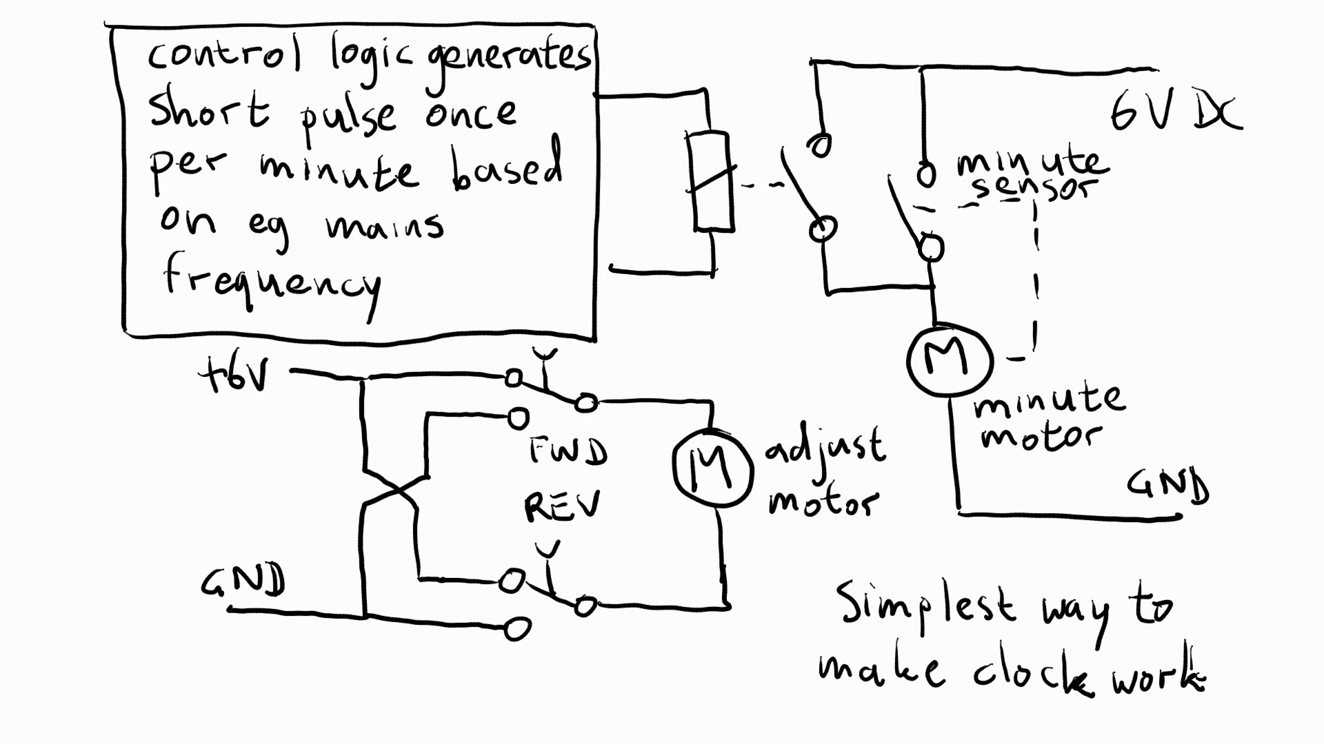
There is no such thing as a FischerTechnik synchronous AC motor (though it's possible to build one) but it's possible to build a clock where all the mechanical parts are FischerTechnik, and keep accurate time with the help of some electronics. The mechanical clock, as shown in the build instructions, uses a DC motor to drive an axle that advances the clock by two minutes (30:1 reduction) every time it goes around, i.e. half of one rotation per minute. There's a switch that gets closed twice per rotation, i.e. for each minute that the clock advances (during normal timekeeping) the switch opens and closes once. Instead of running the motor continuously, we run it only for a short time, once a minute, until the switch opens.
![]()
The simplest way to make the clock work is to put the switch on the minute-axis in series with the "minute motor", so that the motor stops when the minute sensor switch opens. You can then use a relay or a power transistor in parallel with the sensor switch to start a cycle. This relay or transistor needs to be active during a short time (half a second or so) every minute, and this can be implemented by connecting a digital counter to a low voltage AC source via a diode and a Schmidt-trigger, or by using an opto-coupler. The counter has to count 300 (for 50Hz) or 360 (for 60Hz) cycles, and then generate the short pulse.
The minute motor advances the clock every minute, and will keep accurate time on a day-by-day basis, but of course you need to set the clock to the correct time to be useful. The circuit on the bottom left of the schematic shows that a simple circuit with two single-pole-double-throw pushbutton switches, connected to the adjustment motor, is enough to let you adjust the time. And you will only need to do that once (unless there's a power failure or when someone decides we should all temporarily change our time zone by one hour to kid ourselves into thinking that the sun sets later or rises earlier, or vice versa).
Unfortunately I don't have the parts to build the electronics for this (It can be done with FischerTechnik parts but you will need a lot of flipflop modules; it's easier to just do it with TTL or CMOS chips), so I can't show how it's done, but I don't think it'll be too hard to figure out. If you want more details, post a comment and I'll add them.
In the next log, I'll show how to add two more sensor switches to detect that the hands are at the "12 o'clock" position, and how to add an Arduino-controlled FischerTechnik interface to track time with GPS accuracy, and adjust the clock fully automatically. Until I find time to take some more pictures and video and write the next log, check out my Github pages.