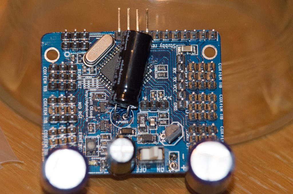
When I got home from work today, I was thrilled to find the package from DirtyPCBs in my mailbox. They have yet again outdone themselves; I received 12 boards, all of which appear to be perfect. (If anyone in USA / Canada wants to try their hand at SMD soldering, drop me an email: $1 / board plus $4 shipping (for up to three boards). Outside of USA / Canada the shipping prices probably don't make sense to buy from me, you are better off ordering directly from DirtyPCBs).
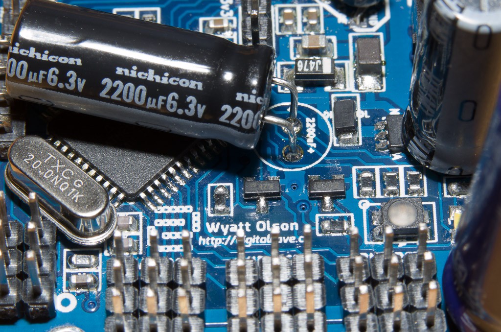
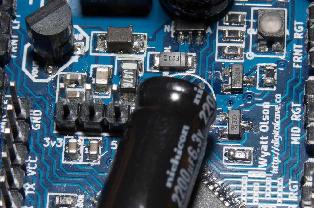
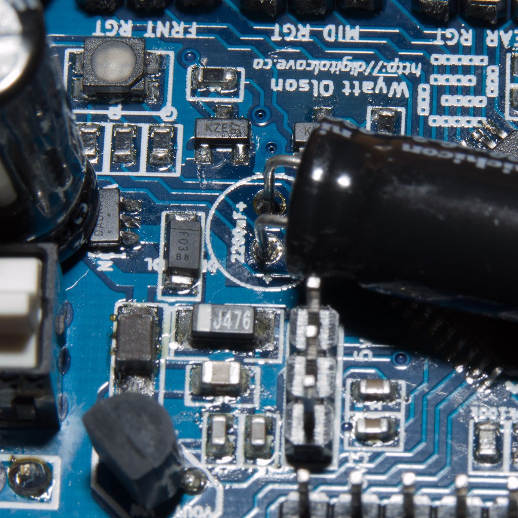
After putting the kids to bed, I started on the soldering. The SMD parts were first, and I took a video of my progress. The SMD bits took about an hour, including applying the solder paste and reflowing it using a heat gun. This was my second real attempt at reflow soldering using this method (I had done a couple of test boards, but I did one 'real' board with a TQFP-32 chip; this one is the second, with more components, tighter spacing, and a TQFP-44 chip).
I consider this attempt at reflow soldering to be a success; there were three solder bridges on the AVR, but a bit of desoldering wick removed all of them, and the AVR is recognised by my usbTinyISP and is able to be successfully programmed (I programmed the fuse bits already, and as soon as I get the rev 2 pins mapped, I will actually program the thing).
Once the SMD components were verified to be working, I soldered the rest of the through hole components, which took another couple of hours (surprisingly, I think that the through hole stuff actually took longer than the SMD work... I guess that there are just a lot of pins):


Next steps are to:
- finish writing the rev 2.0 conditionals in the program (even though the logic is the same, the pins are all different)
- cut the new top layer which fits the rev 2.0 PCB + magnetometer
- figure out how best to attach the distance sensor
- program the distance sensor
- put the whole thing together and see if it works!
Cheers
 The Big One
Discussions
Become a Hackaday.io Member
Create an account to leave a comment. Already have an account? Log In.