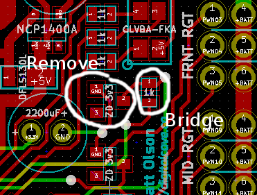
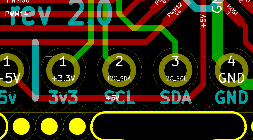
So I have wasted far too many hours these last few days trying to get the Rev 2.0 board to work properly. In the process, I have discovered the following errors. If anyone is using this version of the board, please be aware of these required changes.
- Remove the 3v3 zener diode and resistor between Serial TX and AVR RX, and bridge where the resistor used to be. This is the zener and resistor which are closest to the RGB LED (see screenshot below). I am not sure why this is causing problems; from my understanding of this sort of thing, it should have been perfectly fine (and it works perfectly fine the other way, going from AVR TX to Serial RX). It is possible that I had a bad solder connection. If someone has tried this and got it to work, please let me know.

- The SCL and SDA labels on the board are reversed. As you can see in this screenshot, the net names are correct but the labels are not:

- Pullup resistors on SDA and SCL are required (I used 1k for Rev 1 and had good success there). I had left them off this board since the magnetometer board I selected had 10k resistors built in, but apparently 10k resistors are not enough for high speed i2c communication. If you do not want to put on additional resistors, feel free to reduce i2c speed by using the TWI_FREQ define (from what I have seen, setting it to something like 100000L works). For reference, the default value is 400000L.
All of these bugs have been (or are in the process of being) fixed in Rev 2.1.
Cheers
 The Big One
Discussions
Become a Hackaday.io Member
Create an account to leave a comment. Already have an account? Log In.