Jan
Jan-
Unit ready for deployment
04/26/2018 at 18:33 • 0 commentsUpdate 27.04.18:
![]()
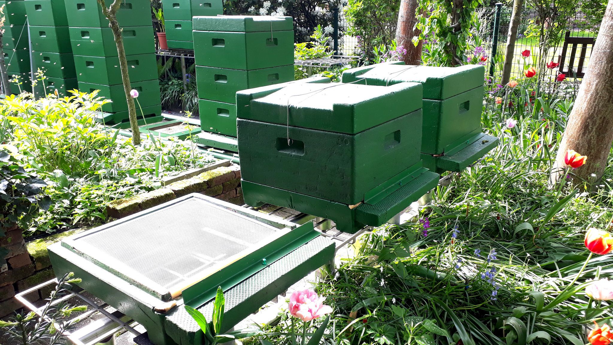
Above: The open spot in the lower left corner is where the new nuc hive will be!
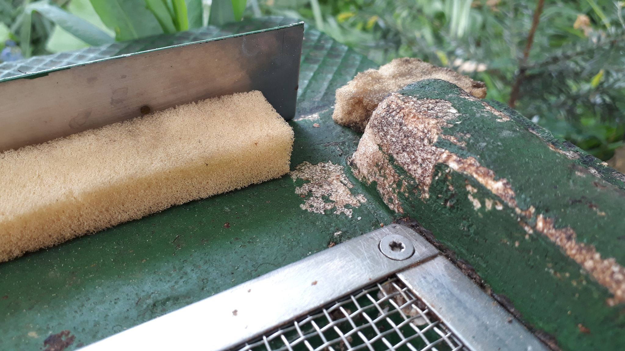
![]()
Above: This will be their entrance for the next 2 weeks. It is kept at about 1 bee-width wide to keep other bees from infiltrating the new hive. They have no time nor the energy to defend themselves yet!
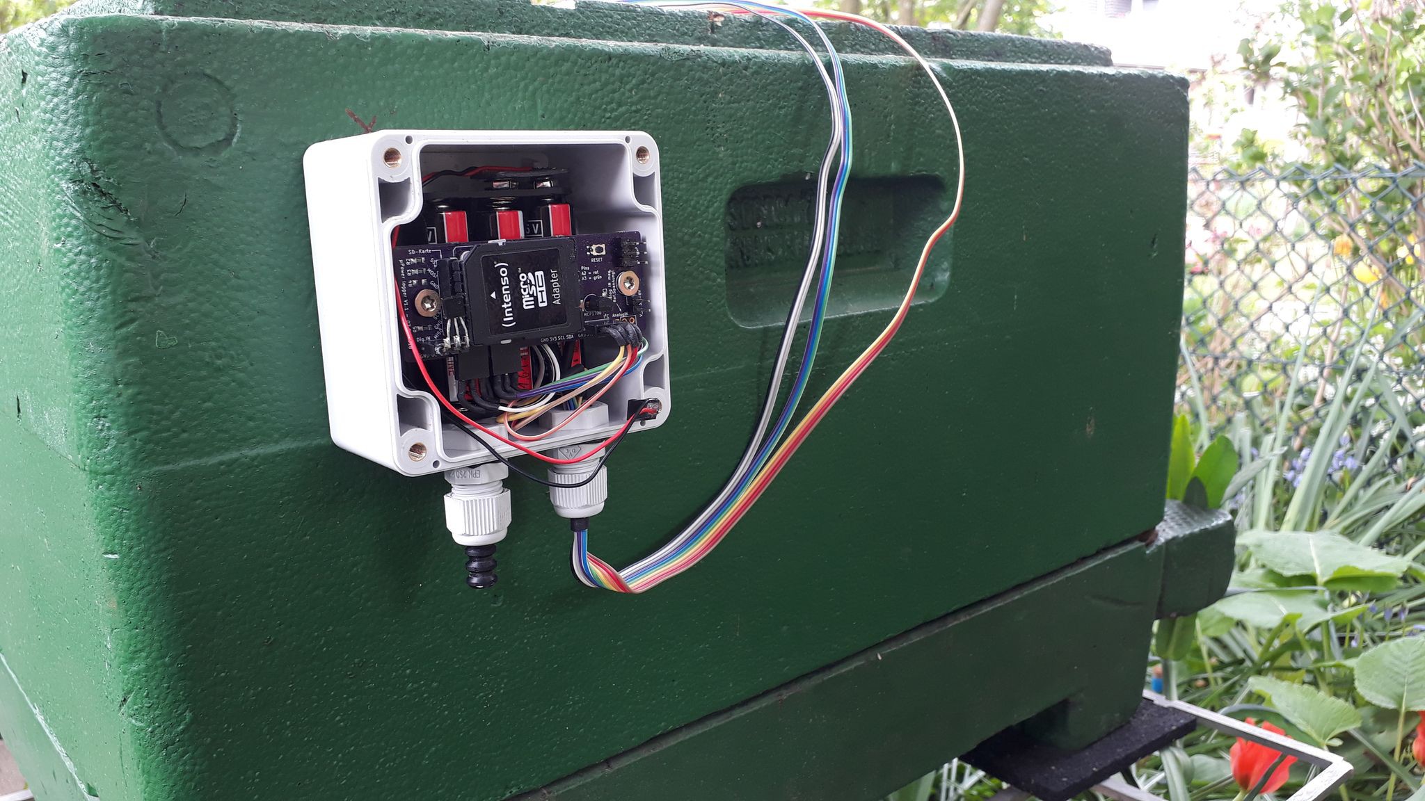
![]()
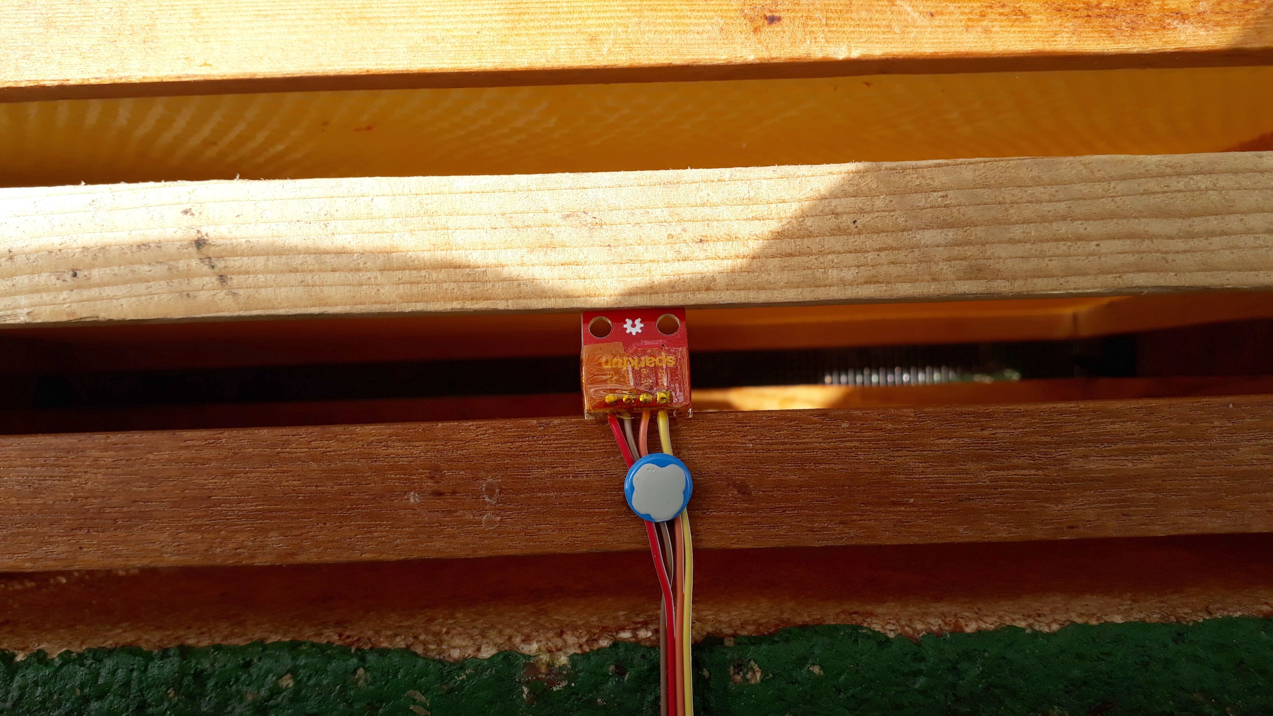
Above: µLogger screwed to the box.
![]()
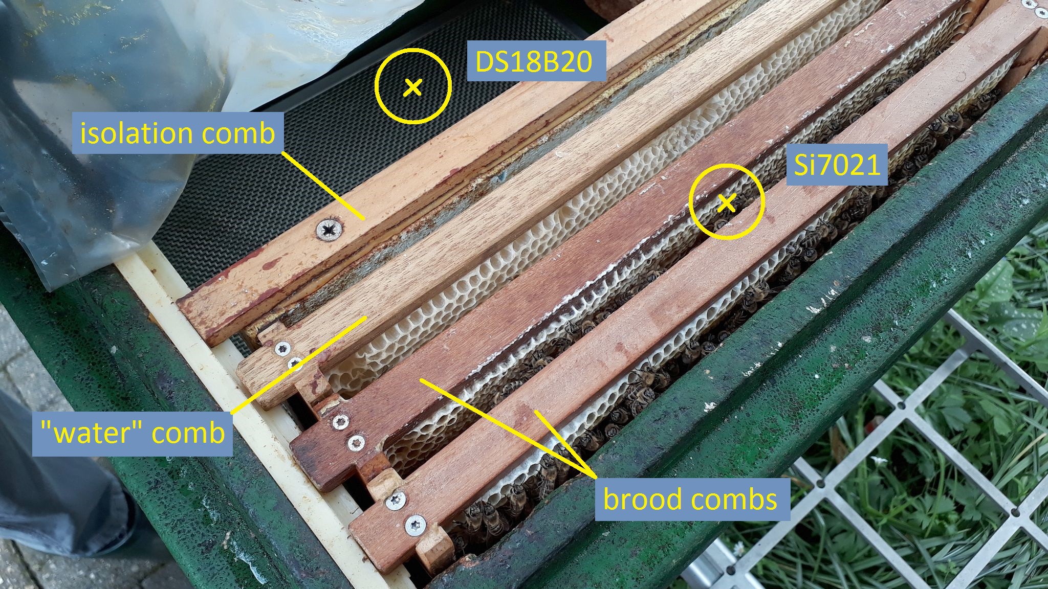
Above: this is how it'll look like. One sensor is in the void to measure the temperature where no bees are, another one goes directly into their entrance. The temp/humidity sensor Si7021 is placed on top between two combs. See next picture:
![]()
Above: position of the Si7021 sensor
---------- more ----------Title says it all:
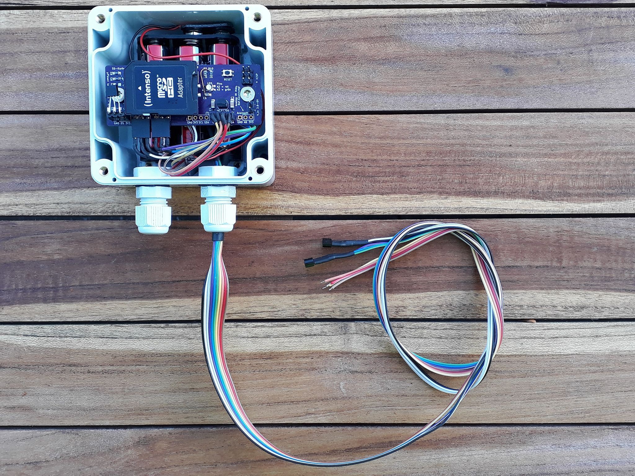
![]()
![]()
I've wired two external DS18B20s and the Si7021 and inserted one DS18B20 directly into the header on the left
Tomorrow we're going to prepare the box for the new bee hive and set up everything. Saturday morning the bees move into their new home!
-
Power consumption
04/23/2018 at 19:07 • 0 commentsI have to make a confession: The µ in µPower is silent... But let me explain my dank joke...
My goal was to get around one year aka 365 days of continuous operation out of 3 AA batteries (not rechargeables). To archive that I read lots of great articles all around the net.
The main culprit seemed to be the power-hungry SD card. Though the SDfat library doesn't officially support switching the cards power supply on and off, it seemed to work for others to reinitialize after power switching. So I decided to use a high-side switch for that purpose (to prevent a floating ground situation).
Thing is: switching it on/off does seem to work sometimes but not always. I mean, switching itself works, the card is working fine after a new SD.begin() call.
But, power consumption is higher in sleep mode than keeping it always on and let the card decide when to sleep! I have to look into that behavior.
Another thing I overlooked when ordering the PCBs is the DS3231. It is supplied directly from the regulator and that's exactly how it isn't done when saving every microamp is what you want (datasheet states up to 0.3mA quiescent current).
Actual power consumption
In sleep mode (power down with BOD and ADC disabled) the whole thing sips 0.350 to 0.380mA from the batteries. This includes the Atmega, 3x DS18B20, 1x Si7021, the RTC and the high-side switch.
That's not too shabby, but I guess I could cut that by at least another 0.1mA when powering the RTC from an Atmega pin.
Battery capacity
The batteries are Ansmann industrial alkaline AAs. They're 1.65V open-circuit and rated for "2700 mAh discharge at 10mA load; 24hours/day; End Voltage (EV): 0.8V"
We need to take into account that we don't have that constant load characteristics here. The MCP1700 does need at least 3.6V @200mA load (SD card open/write can get this high) for proper operation. This results in: 1.2V/cell maximum discharge voltage. I'm wasting capacity here, so I have to switch to 4 cells. That way I can discharge them to 0.9V/cell.Another problem could be unevenly discharged cells as I do not use any balancing. With thee cells the difference between cells was something like 0.1V max, so I guess that's fine.
Actual operating time
Time will tell... I guess it will be somewhere around 120 to 180 days. That's not a year, I know but I'm ok with that.
The unit does voltage measuring before every SD write to prevent data loss and shuts down if the voltage is too low.
to be continued...
-
Getting data from inside of a nuc bee hive
04/22/2018 at 12:39 • 0 commentsIntroduction
So, bees are fascinating creatures. They come in many sizes, colors and shapes. The ones I will get my data from are of the western honey bee variety.
Bees have many ways to cope with hot and cold climates and too high/low humidity. All these things have been researched extensively. But I'd love to record my own data from a live bee hive to see exactly what these smart critters do to keep a steady climate in their hive!
The hive
The hive itself starts from scratch in a few weeks. We take two brood combs from another hive and a few hundred bees and put them into a new box. A comb full of honey and an empty honeycomb, sprayed with water is added as well!
The rest of the box is left empty.
In the following days fascinating things will happen:
- the bees are going to raise a new queen, as they don't have one yet. This will take around three weeks. Food and water come from the honey combs and water comb. They don't have to leave the hive for that!
- the new queen leaves the hive to mate with one or more male bees. After that she will return to the hive (we hope she does!). This usually takes a few days
- meanwhile the rest of the bees hatches from their cells and begin working for the hive
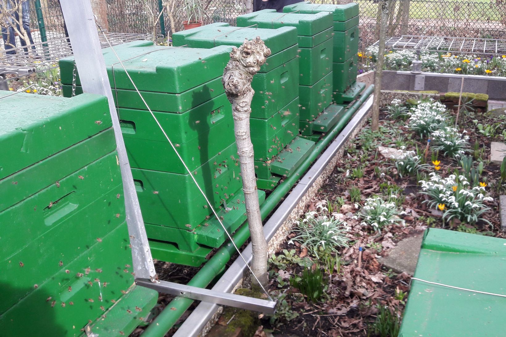
The box itself is a Segeberger type made from styrofoam. They are painted on the outside in a non-toxic green color:
![]()
What data and positioning of the sensors
I'm going to track the following things:
- outside temperature (DS18B20)
- inside temperature between two combs (DS18B20)
- inside temperature at the entrance (DS18B20)
- humidity and temperature on top of the combs (Si7021)
Logging interval
Measurements are taken every 15 Minutes, resulting in 96 logs per day (24h) to create nice graphs. The system itself is quite "lagging". One won't see temperature or humidity jumping up and down by a few °C/%RH within minutes.
Data retention
Logs are stored in the Atmega328s EEPROM. The measurements are put into a human readable string together with a time stamp. When the EEPROM is full (holds 34 strings of 30 bytes), the log is written to the SD.
I use the EEPROMex librarys update function to keep wear aof the EEPROM low. The EEPROM is full every 8,5 hours, so in theory I get like 850000 hours (datasheet guarantees 100000 write cycles) before data retention is not guaranteed anymore.
This data can later be directly imported in Calc or whatever program (I think I'm going to use Kst...) and converted to a chart.
-
PCB and components
04/21/2018 at 10:58 • 0 commentsDesigning a PCB is hard work (if you can't decide...)
I very quickly had all of the loggers features written down and began choosing components.
From that moment on, it kicked in: creeping featurism. And let me be clear: I DON'T want that nor do I need that. It's just always the case when I start creating a PCB.
I just wanted to track 3 temperatures and humidity plus maybe brightnes. But NO, let's add this let's add that. So creating the layout took me way longer than I'd like to admit...
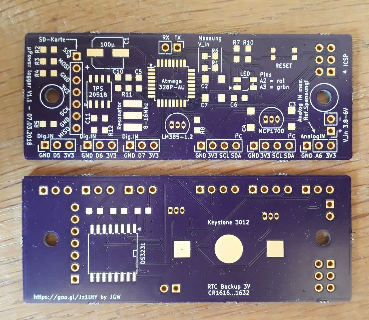
After a while I thought to myself: f*#!? it, I need to get that board ready by april, bees ain't got no time fo that! So I decided to throw out lots of headers, parts and features and get to the really basic functions and board I needed:
![]()
The board arrived after a wait time of just 2,5 weeks (USA-Germany). Amazing! Quality is just top notch, as well as the service. I ordered a wrong version, just mailed them my mistake and a few hours later that order was canceled and my money refunded. I will definately order again @oshpark !!!
You may wonder about that strange way to add the micro SD card. It's a method I like for prototyping and breadboarding and I had no micro SD sockets at hand.
So I chose the angled pin headers to micro SD adapter route.
The SD card can be (dis)connected to the 3V3 rail by a high-side switch to save precious microamps while the card is not used.Everything else is pretty straight-forward: MCP1700/1703 regulator, a two-color signal LED, DS3231 for timekeeping, battery holder for backup.
I've also added a LM385-1.2 for a precise reference voltage to the AREF of the Atmega. More on that approach later on...
Errors in the PCB
I checked everything before sending the gerbers to OSHpark, but a few things went unnoticed. Those were easily fixed but anyway, don't forget these things:
- AVCC needs to be conneced to VCC of the Atmega. Otherwise you won't be able to operate. Just forgot that connection in the circuit... Fixed by a short piece of wire to VCC.
- the ground pad for the coin cell needs to be bigger. Solder stop mask is higher than the pad. Fixed by adding a bit of solder!
- make pads large enough for good heat transfer. Those MCP and LM385 pads are too damn small...
Other design "fails"
Not an error but the DS3231 is powered directly from the MCP1700 in this revision. It consumes up to (haven't measured it) 0,3mA. In my next board run the chip is going to be pin-powered by the Atmega.
µPower (beehive) SD logger
Let's observe an emerging beehive throughout the year 2018! (And create an logger from scratch for that purpose)