This project is a subproject of #Ion wind loudspeaker experiments.
==First version - open loop
So, how to make it? well, first up, I started searching for high voltage transistors. The largest voltages I could find were some 2 kV, which isn't too bad, but would certainly require some sort of a chain, which is rather tricky.
Also, applying too much voltage to a transistor causes breakdown. While breakdown itself isn't too destructive, a breakdown made by a spark from a capacitor will kill the transistor very quickly. So I needed some rock-solid protection...
And then I saw some scrap vacuum tubes someone threw away, and it became obvious that a vacuum tube is an ideal solution:
* high voltage is the territory of tubes. They simply need high voltages.
* unlike a transistor, a tube has no breakdown voltage. One can substantially violate maximum voltage spec without any immediate consequences (although, it may reduce tube's life, it isn't a problem for experiments, where total run time is very small)
* Thus, a spark in the blower will cause no damage to the tube, and no protection circuitry is needed. Beauty!
So I obtained a high-voltage tube (a tetrode), and made an amplifier.
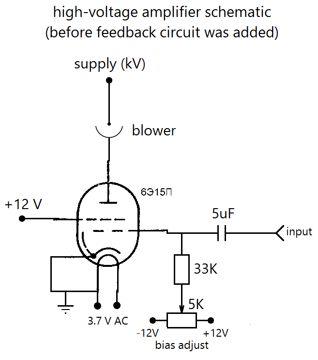 Oops, drawn back-to-front (input should have been on the left-hand-side).
When I powered it up, I got quite a lot of quiescent current (some sort of leakage), regardless of how much negative bias I applied. This was a bit of a fail, but then I thought that I can easily lower that quiescent current by redusing the temperature of cathode. So I reduced heater voltage from the nominal 6.3 V down to 3.7 V, and that worked beautifully!
==Improvement - adding feedback
Some time after playing with the open-loop version, I realized I want to try to force a voltage (not current) across the highly nonlinear load I have. And the way to do it is to introduce feedback.
The first challenge of doing the feedback turned out to be in making a high voltage divider. It turned out to be much more complicated than I originally anticipated. The main reason for that is that parasitic capacitances, often negligible in low-voltage electronics, are not negligible here.
See #High-voltage oscilloscope probe project for details on how to make the divider.
The rest of feedback circuit is quite straightforward.
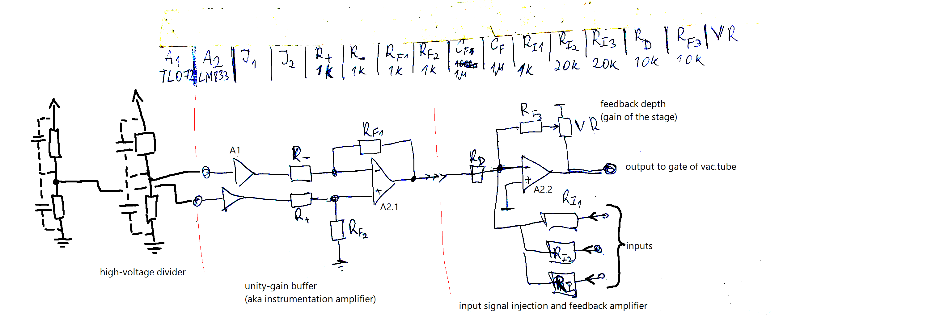
High-voltage dividers form a differential input. They are to be connected to the load (in some cases, I connected to specific part of load, that allowed me to effectively force a voltage across the part).
'Feedback depth' trimpot allows to adjust depth of feedback of the whole system. The reason for adding this pot was stability - it is not generally possible to regulate a voltage with a current-source.
I added multiple inputs. One is used to feed in the music, the other is rewired to bias adjustment pot. The last is a spare, not used.
 DeepSOIC


 mircemk
 Christoph
whoah. This is beautiful. (although having several kilovolts of potential difference sitting like that in the open is asking for trouble).